Note : Les descriptions sont présentées dans la langue officielle dans laquelle elles ont été soumises.
CA 02516882 2005-08-23
NFC-316
INDUSTRIAL TWO-LAYER FABRIC
Technical Field of the Invention
The present invention relates to an industrial two-
s layer fabric used for transport, dehydration and the like,
particularly suited for papermaking.
Background Art
Fabrics obtained by weaving warps and wefts have
conventionally been used widely as an industrial fabric.
They are, for example, used in various fields including
papermaking wires, conveyor belts and filter cloths and are
required to have fabric properties suited for the intended
use or using environment. Of such fabrics, a papermaking
wire used in a papermaking step for removing water from raw
materials by making use of the network of the fabric must
satisfy a severe demand. There is therefore a demand for
the development of fabrics which do not transfer a wire
mark of the fabric and therefore have excellent surface
property, have enough rigidity and therefore are usable
desirably even under severe environments, or are capable of
maintaining conditions necessary for making good paper for
a prolonged period of time. In addition, fiber supporting
property, improvement in a papermaking yield, good water
drainage property, wear resistance, dimensional stability
and running stability are demanded. In recent years, owing
to the speed-up of a papermaking machine, requirements for
papermaking wires become severe further.
- 1 -
CA 02516882 2005-08-23
NFC-316
Since most of the demands for industrial fabrics and
solutions thereof can be understood if papermaking fabrics
on which the most severe demand is imposed among industrial
fabrics will be described, the present invention will
hereinafter be described by use of the papermaking fabric
as a representative example.
In the paper making machine, an increase in paper
making speed inevitably raises dehydration speed so that
dehydration power must be reinforced. Examples of the
fabric with good dehydration property include two-layer
fabric having a dehydration hole penetrating from the upper
surface side toward the lower surface side of the fabric.
Particularly, a two-layer fabric using a warp binding yarn
which is woven with an upper surface side weft and a lower
surface side weft to constitute the upper surface side
surface design and the lower surface side surface design is
developed with a view to satisfying the surface property,
fiber supporting property and dehydration property which a
papermaking fabric is required to have. A two-layer fabric
using a warp binding yarn is described in Japanese Patent
Laid-Open No. 2004-36052. In the fabric disclosed in the
above-described invention, a warp functions as a binding
yarn for weaving the upper surface side layer with the
lower surface side layer. A pair of two warp binding yarns
simultaneously and mutually complement a portion of the
upper surface side surface design and a portion of the
lower surface side surface design to form each surface
design so that the fabric has excellent surface property
- 2 -
CA 02516882 2005-08-23
NFC-316
and binding strength. The lower surface side design of the
fabric in Examples 1 to 3 of Japanese Patent Laid-Open No.
2004-36052 is however a ribbed design in which two lower
surface side warps are arranged in parallel while having
the same design and a crimp of a lower surface side weft
corresponds to only two warps so that the fabric has poor
wear resistance.
Summary of the Invention
The above-described two-layer fabric has dehydration
holes penetrating completely from the upper surface side
layer toward the lower surface side layer and these holes
are arranged over the whole surface so that the fabric has
good dehydration property. They are however such drawbacks
as sticking, into the fiber, of a sheet raw material over a
wire or loss of fiber or filler owing to strong vacuum,
which sometimes leads to remarkable generation of
dehydration marks.
Thus, industrial fabrics capable of satisfying all of
the surface property, fiber supporting property and wear
resistance have not yet been developed.
With the foregoing problems in view, the present
invention has been made. An object of the present invention
is to provide an industrial fabric capable of preventing
drastic dehydration and generation of dehydration marks
resulting therefrom and having excellent surface property,
fiber supporting property and wear resistance.
- 3 -
CA 02516882 2005-08-23
NFC-316
The present invention relates to an industrial two-
layer fabric which comprises eight pairs of warps obtained
by arranging eight upper surface side warps and eight lower
surface side warps, and a plurality of upper surface side
wefts and lower surface side wefts, and has an upper
surface side layer and a lower surface side layer bound
with warp-direction yarns. In the~lower surface side layer,
warps are formed by successively arranging a design in
which one warp passes over four successive lower surface
side wefts, passes under one lower surface side weft,
passes over two lower surface side wefts, and passes under
one lower surface side weft while shifting the design by
three lower surface side wefts, and two adjacent lower
surface side warps simultaneously weave therein, from the
lower surface side, one lower surface side weft, thereby
forming a weft long crimp of the lower surface side weft
corresponding to six lower surface side warps over the
lower surface side surface and at the same time, arranging
a lower surface side warp in a zigzag manner while
alternately adjoining the lower surface side warps on both
sides adjacent thereto.
The upper surface side warps) and lower surface side
warps) of at least one of the eight pairs of an upper
surface side warp and a lower surface side warp arranged
vertically may be both warp binding yarns which are woven
with an upper surface side weft and a lower surface side
weft to constitute a portion of an upper surface side
surface design and a portion of a lower surface side
- 4 -
CA 02516882 2005-08-23
NFC-316
surface design. The warp binding yarns forming the pair may
be woven with respective upper surface side wefts and
cooperatively function as one warp constituting an upper
surface side complete design on an upper surface side
surface, while on the lower surface side surface, the pair
of warp binding yarns constitute a lower surface side
surface design similar to that constituted by a lower
surface side warp.
The upper surface side warps) of at least one of the
eight pairs of an upper surface side warp and a lower
surface side warp arranged vertically may be each a warp
binding yarn which is woven with an upper surface side weft
and a lower surface side weft to constitute a portion of an
upper surface side surface design and a portion of a lower
surface side surface design; in the pair of the warp
binding yarn and lower surface side warp, the warp binding
yarn may be woven with an upper surface side weft to
functions as one warp constituting an upper surface side
complete design on an upper surface side surface, while on
the lower surface side surface, the pair of the warp
binding yarn and lower surface side warp cooperatively
constitutes a lower surface side surface design similar to
that constituted by the other lower surface side warps.
The lower surface side warps) of at least one of the
eight pairs of an upper surface side warp and a lower
surface side warp arranged vertically may be a warp binding
yarn which is woven with an upper surface side weft and a
lower surface side weft to constitute a portion of an upper
- 5 -
CA 02516882 2005-08-23
NFC-316
surface side surface design and a portion of a lower
surface side surface design. In the pair of the warp
binding yarn and the upper surface side warp, the warp
binding yarn and upper surface side warp may be woven with
respective upper surface side wefts and cooperatively
function as one warp constituting an upper surface side
complete design on an upper surface side surface, while on
the lower surface side surface, the warp binding yarn
constitutes a lower surface side surface design similar to
that constituted by a lower surface side warp.
One of the warp binding yarns forming the pair may be
woven with at least one upper surface side weft to form an
upper surface side surface design, under which the other
warp binding yarn may be woven with one lower surface side
weft, while the one warp binding yarn may be woven with one
lower surface side weft, over which the other warp binding
yarn may be woven with at least one upper surface side weft
to constitute the upper surface side surface design,
whereby the pair of warp binding yarns mutually complement
the upper surface side surface design and lower surface
side surface design, thereby forming each surface design.
The upper surface side complete design may be composed
of either one warp complete design or of at least two warp
complete designs. The upper surface side surface design
may be any one of 2-shaft plain weave, 4-shaft twill weave,
4-shaft broken twill weave, 8-shaft twill weave and 8-shaft
broken twill weave.
One or at least two auxiliary wefts may be inserted
- 6 -
CA 02516882 2005-08-23
NFC-316
between upper surface side wefts. The number of upper
surface side wefts may be 1 to 2 times the number of lower
surface side wefts. The diameter of an upper surface side
warp may be equal to that of a lower surface side warp.
In an industrial two-layer fabric which comprises
eight pairs of warps obtained by vertically arranging eight
upper surface side warps and eight lower surface side warps,
and a plurality of upper surface side wefts and lower
surface side wefts, and has an upper surface side layer and
a lower surface side layer bound with warp-direction yarns,
the lower surface side layer is formed in such a manner
that warps are formed with a complete design obtained by
successively arranging a design in which one warp passes
over four successive lower surface side wefts, passes under
one lower surface side weft, passes over two lower surface
side wefts, and passes under one lower surface side weft,
while shifting this design by three lower surface side
wefts; two adjacent lower surface side warps simultaneously
weave therein, from the lower surface side, one lower
surface side weft, thereby forming a weft long crimp of a
lower surface side weft corresponding to six lower surface
side warps on the lower surface side surface and at the
same time, arranging a lower surface side warp in a zigzag
manner while adjoining the lower surface side warps on both
sides adjacent thereto. This makes it possible to improve
the rigidity, oblique rigidity and wear resistance of the
fabric. Moreover, since water drainage property is made
uneven by forming both an overlapped portion and a non-
CA 02516882 2005-08-23
NFC-316
overlapped portion between warp-direction yarns
constituting the upper surface side layer and warp-
direction yarns constituting the lower surface side layer,
dehydration occurs stepwise and therefore, generation of
dehydration marks, sticking of a sheet raw material on a
wire, loss of fiber or filler can be suppressed.
Brief Description of the Drawings
FIG. 1 is a design diagram illustrating the complete
design of Example 1 of the present invention.
FIGS. 2A and 2B are cross-sectional views along the
lines IIA-IIA and IIB-IIB at the warps 1 and 2 of FIG. 1
respectively.
FIG. 3 is a cross-sectional view along the line III-
III at the weft 1' of FIG. 1.
FIG. 4 is a design diagram illustrating the complete
design of Example 2 of the present invention.
FIGS. 5A and 5B are cross-sectional views along the
lines VA-VA and VB-VB at the warps 1 and 2 of FIG. 4
respectively.
FIG. 6 is a cross-sectional view along the line VI-VI
at the weft 2' of FIG. 4.
FIG. 7 is a design diagram illustrating the complete
design of Example 3 of the present invention.
FIGS. 8A and 8B are cross-sectional views along the
lines VIIIA-VIIIA and VIIIB-VIIIB at the warps 1 and 2 of
FIG. 7 respectively.
FIG. 9 is a cross-sectional view along the line IX-IX
_ g -
CA 02516882 2005-08-23
NFC-316
at the weft 2' of FIG. 7.
FIG. 10 is a design diagram illustrating the complete
design of Example 4 of the present invention.
FIGS. 11A and 11B are cross-sectional views along the
lines XIA-XIA and XIB-XIB at the warps 1 and 2 of FIG. 10
respectively.
FIG. 12 is a cross-sectional view along the line XII-
XII at the weft 1' of FIG. 10.
FIG. 13 is a design diagram illustrating the complete
design of Example 5 of the present invention.
FIGS. 14A and 14B are cross-sectional views along the
lines XIVA-XIVA and XIVB-XIVB at the warps 1 and 2 of FIG.
13 respectively.
FIG. 15 is a cross-sectional view along the line XV-XV
at the weft 3' of FIG. 13.
FIG. 16 is a design diagram illustrating the complete
design of Example 6 of the present invention.
FIGS. 17A and 17B are cross-sectional views along the
line XVIIA-XVIIA and XVIIB-XVIIB at the warps 1 and 2 of
FIG. 16 respectively.
FIG. 18 is a cross-sectional view along the line
XVIII-XVIII at the weft 1' of FIG. 16.
FIG. 19 is a design diagram illustrating the complete
design of Example 7 of the present invention.
FIGS. 20A and 20B are cross-sectional views along the
lines XXA-XXA and XXB-XXB at the warps 1 and 2 of FIG. 19
respectively.
FIG. 21 is a cross-sectional view along the line XXI-
- g -
CA 02516882 2005-08-23
NFC-316
XXI at the weft 2' of FIG. 19.
FIG. 22 is a design diagram illustrating the complete
design of Example 8 of the present invention.
FIGS. 23A and 23B are cross-sectional views along the
lines XXIIIA-XXIIIA and XXIIIB-XXIIIB at the warps 1 and 2
of FIG. 22 respectively.
FIG. 24 is a cross-sectional view along the line XXIV-
XXIV at the weft 1' of FIG. 22.
FIG. 25 is a design diagram illustrating the complete
design of Example 9 of the present invention.
FIGS. 26A and 26B are cross-sectional views along the
lines XXVIA-XXVIA and XXVIB-XXVIB at the warps 1 and 2 of
FIG. 25 respectively.
FIG. 27 is a cross-sectional view along the line
XXVII-XXVII at the weft 4' of FIG. 25.
FIG. 28 is a design diagram illustrating the complete
design of Example 10 of the present invention.
FIGS. 29A and 29B are cross-sectional views along the
lines XXIXA-XXIXA and XXIXB-XXIXB at the warps 1 and 2 of
FIG. 28 respectively.
FIG. 30 is a cross-sectional view along the line XXX-
XXX at the weft 1' of FIG. 28.
FIG. 31 is a design diagram illustrating the complete
design of Example 11 of the present invention.
FIGS. 32A and 32B are cross-sectional views along the
line XXXIIA-XXXIIA and XXXIIB-XXXIIB at the warps 1 and 2
of FIG. 31 respectively.
FIG. 33 is a cross-sectional view along the line
- 10 -
CA 02516882 2005-08-23
NFC-316
XXIII-XXIII at the weft 2' of FIG. 31.
Detailed Description of the Invention
The present invention provides an industrial two-layer
fabric which comprises eight pairs of warps obtained by
vertically arranging eight upper surface side warps and
eight lower surface side warps, and a plurality of upper
surface side wefts and lower surface side wefts, and has an
upper surface side layer and a lower surface side layer
bound with warp-direction yarns, characterized in that in
the lower surface side layer, warps have a design in which
one warp passes over four successive lower surface side
wefts, passes under one lower surface side weft, passes
over two successive lower surface side wefts, and passes
under one lower surface side weft; a lower surface side
warp adjacent to the above-described one is formed by
arranging the above-described design while shifting it by
three upper surface side wefts; two adjacent lower surface
side warps simultaneously weave therein, from the lower
surface side, one lower surface side weft, thereby forming
a weft long crimp corresponding to six lower surface side
warps over the lower surface side surface and at the same
time, arranging a lower surface side warp in a zigzag
manner while alternately adjoining the lower surface side
warps on both sides adjacent thereto.
Two adjacent lower surface side warps firmly weave
therein a lower surface side weft so that the resulting
fabric has excellent rigidity. In addition, a weft long
- 11 -
CA 02516882 2005-08-23
NFC-316
crimp corresponding to six lower surface side warps is
formed on the lower surface side surface so that the
resulting fabric has improved wear resistance. Moreover,
the number of weaving times of a lower surface side weft
with a warp is small so that it is possible to increase the
shooting count of the lower surface side weft or widen its
diameter. An overlapped portion and a non-overlapped
portion between warp-direction yarns constituting the upper
surface side layer and warp-direction yarns constituting
the lower surface side layer are caused to exist as a
mixture by employing a design in which a lower surface side
warp is zigzag arranged while adjoining lower surface side
warps on both sides adjacent thereto. Owing to this
structure, a network having a free size or shape can be
formed, which permits stepwise progress of dehydration and
makes it possible to inhibit generation of dehydration
marks, sticking of a sheet raw material on a wire and loss
of fiber or filler. Moreover, the resulting fabric has
improved rigidity in its oblique direction by arranging
lower surface side warps in a zigzag manner.
The industrial two-layer fabric of the present
invention is composed of eight pairs of warps obtained by
arranging eight upper surface side warps and eight lower
surface side warps vertically, and a plurality of upper
surface side wefts and lower surface side wefts. As a
binding yarn for weaving the upper surface side layer with
the lower surface side layer, employed is a warp binding
yarn woven with an upper surface side weft and a lower
- 12 -
CA 02516882 2005-08-23
NFC-316
surface side weft to constitute a portion of an upper
surface side surface design and a portion of a lower
surface side surface design.
The warp binding yarn is arranged in any one of the
following manners: at least one pair, of eight pairs of an
upper surface side warp and a lower surface side warp
vertically arranged, has two warp binding yarns instead of
the upper surface side warp and lower surface side warp; at
least one pair, of eight pairs of an upper surface side
warp and a lower surface side warp vertically arranged, has
a warp binding yarn, which has been substituted for the
upper surface side warp, and the lower surface side warp;
and at least one pair, of eight pairs of an upper surface
side warp and a lower surface side warp vertically arranged,
has a warp binding yarn, which has been substituted for the
lower surface side warp, and the upper surface side warp.
The term "pair" as used herein means a pair of one upper
surface side warp and one lower surface side warp
vertically arranged and to be woven with an upper surface
side weft and a lower surface side weft, respectively. In
the present invention, eight upper surface side warps and
eight lower surface side warps constitute eight pairs.
When two warp binding yarns form a pair, they are
woven with respective upper surface side wefts and
cooperatively function as one warp constituting an upper
surface side complete design on the upper surface side
surface, while on the lower surface side surface, they form
a lower surface side surface design similar to that formed
- 13 -
CA 02516882 2005-08-23
NFC-316
by another lower surface side warp. Particularly in this
design, one of the warp binding yarns forming the pair is
woven with at least one upper surface side weft to form an
upper surface side surface design, under which the other
warp binding yarn is woven with one lower surface side weft,
while the one warp binding yarn is woven with one lower
surface side weft, over which the other warp binding yarn
is woven at least one upper surface side weft to constitute
the upper surface side surface design. Thus, the pair of
warp binding yarns is able to form the upper surface side
surface design and lower surface side surface design by
mutually complement them.
In the case of the pair of a warp binding yarn and a
lower surface side warp, the warp binding yarn is woven
with an upper surface side weft and functions as one warp
constituting an upper surface side complete design on the
upper surface side surface, while on the lower surface side
surface, the warp binding yarn and lower surface side warp
cooperatively form a lower surface side surface design
similar to that formed by another lower surface side warp.
In the case of the pair of a warp binding yarn and an
upper surface side warp, the warp binding yarn and upper
surface side warp are woven with respective upper surface
side wefts and cooperatively function as one warp
constituting an upper surface side complete design on the
upper surface side surface, while on the lower surface side
surface, the warp binding yarn forms a lower surface side
surface design similar to that formed by a lower surface
- 14 -
CA 02516882 2005-08-23
- NFC-316
side warp.
In the fabric of the present invention, binding is
achieved by a warp binding yarn extending in a warp
direction. The yarn serving as a binding yarn is a warp-
s direction one constantly under tension. Compared with a
conventional thin weft binding yarn, it has a very strong
power for binding the upper surface side layer and the
lower surface side layer and has good adhesion. Accordingly,
problems such as weakening of a binding power owing to
internal wear caused by friction between these two layers,
appearance of a space between layers and separation of two
layers scarcely occur. In addition, since an additional
binding yarn such as weft binding yarn is not necessary, it
is possible to increase the shooting count of wefts or
widen the diameter of a weft, which leads to improvement in
the rigidity of a whole fabric.
The lower surface side complete design composed of
warp binding yarns, lower surface side warps and lower
surface side wefts is formed by successively arranging a
design in which a warp passes over four successive lower
surface side wefts, passes under one lower surface side
weft, passes over two lower surface side wefts and passes
under one lower surface side weft, while shifting this
design by three lower surface side wefts. All the warp
designs constituting the lower surface side complete design
are the same. In other words, a pair of warp binding yarns
also forms a lower surface side surface design similar to
that formed by a lower surface side warp. The pair of a
- 15 -
CA 02516882 2005-08-23
NFC-316
warp binding yarn and a lower surface side warp and the
pair of a warp binding yarn and an upper surface side warp
each forms a lower surface side surface design similar to
that formed by a lower surface side warp.
No particular limitation is imposed on the upper
surface side complete design composed of warp binding yarns,
upper surface side warps and upper surface side wefts. The
warp binding yarns forming the pair may be woven with
respective upper surface side wefts and cooperatively
function as one warp constituting the upper surface side
complete design. This also applies to the pair of a warp
binding yarn and an upper surface side warp and they may
cooperatively function as a warp constituting the upper
surface side complete design. In the case of the pair of a
warp binding yarn and a lower surface side warp, the lower
surface side warp is not woven with an upper surface side
weft so that only the warp binding yarn may be woven with
an upper surface side weft to function as a warp. One or at
least two warp complete designs may form the upper surface
side complete design. For example, they may be any one of a
1/3 design in which an upper surface side warp passes over
one upper surface side weft and then passes under three
successive upper surface side wefts, a 2/2 design in which
an upper surface side warp passes over two upper surface
side wefts and passes under two successive upper surface
side wefts, and a design having both the 1/3 design and 2/2
design on one upper surface side surface. The design can be
selected as needed. Preferred examples include 2-shaft
- 16 -
CA 02516882 2005-08-23
NFC-316
plain weave, 4-shaft twill weave, 4-shaft broken twill
weave, 8-shaft twill weave and 8-shart broken twill weave.
One or at least two auxiliary wefts may be placed
between upper surface side wefts. The auxiliary weft,
together with an upper surface side weft, forms the upper
surface side surface design, fills the space between the
upper surface side wefts, thereby improving the fiber
supporting property, and flattens the irregularities which
are otherwise formed by a weft knuckle, thereby improving
the surface property. No particular limitation is imposed
on the design formed by the auxiliary weft and it can be
selected depending on the application or using purpose. In
order to improve the fiber supporting property, it is
recommended to adopt a design in which a long crimp by
auxiliary wefts is formed between upper surface side wefts.
No particular limitation is imposed on the diameter of the
auxiliary weft, but it is preferred to set it smaller than
that of an upper surface side weft. Although no particular
limitation is imposed on the ratio of auxiliary wefts, a
ratio of upper surface side wefts and auxiliary wefts may
be 1:1, 2:1, 3:2 or the like. Although no particular
limitation is imposed on the arrangement ratio of warp
binding yarns, it is necessary to place at least one warp
binding yarn because it serves as a binding yarn. The
fabric of the present invention has eight pairs of warps
having eight upper surface side warps and eight lower
surface side warps arranged vertically, so that the four
pairs of an upper surface side warp and a lower surface
- 17 -
CA 02516882 2005-08-23
NFC-316
side warp, out of eight pairs, are replaced with pairs of
warp binding yarns and the pair of warp binding yarns and
the pair of an upper surface side warp and a lower surface
side warp may be arranged alternately; or the pair of a
warp binding yarn and a lower surface side warp and the
pair of an upper surface side warp and a lower surface side
warp may be arranged at a ratio of 1:3. The number of warp
binding yarns may be increased to improve the binding
strength. The ratio of warp binding yarns can be selected
as needed, depending on the weaving conditions, using
purpose, or the like.
A ratio of an upper surface side weft and a lower
surface side weft may be 2:1, 1:1, 3:2 or the like. At 2:1
or 3:2 which means dense arrangement of upper surface side
wefts and rough arrangement of lower surface side wefts,
the fabric has improved wear resistance, because the
diameter of the lower surface side weft can be thickened
easily.
No particular limitation is imposed on a yarn to be
used in the present invention and it can be selected freely
depending on the properties which an industrial fabric is
desired to have. Examples of it include, in addition to
monofilaments, multifilaments, spun yarns, finished yarns
subjected to crimping or bulking such as so-called textured
yarn, bulky yarn and stretch yarn, marled yarn and yarns
obtained by intertwining them. As the cross-section of the
yarn, not only circular form but also square or short form
such as stellar form, or elliptical or hollow form can be
- 18 -
CA 02516882 2005-08-23
NFC-316
used. The material of the yarn can be selected freely and
usable examples of it include polyester, nylon,
polyphenylene sulfide, polyvinylidene fluoride, ethylene
tetrafluoride, polypropylene, aramid, polyether ether
ketone, polyethylene naphthalate, cotton, wool and metal.
Of course, yarns obtained using copolymers or incorporating
or mixing the above-described material with a substance
selected depending on the intended purpose may be used.
As the upper surface side warps, lower surface side
warps, upper surface side wefts and warp binding yarns, use
of a polyester monofilament having rigidity and excellent
dimensional stability is usually preferred. When lower
surface side wefts which need wear resistance are obtained
by interweaving of polyester monofilaments and polyamide
monofilaments while arranging them alternately, they are
able to have wear resistance without losing rigidity.
It is also possible to place a plurality of yarns with
the same design at a position where one yarn is normally
placed from the standpoint of design. Arrangement of a
plurality of yarns having a thin diameter brings about
improvement in surface property and thinning of the fabric.
Examples
Examples of the present invention will hereinafter be
described based on accompanying drawings.
FIGS. l, 4, '~, 10, 13, 16, 19, 22, 25, 28 and 31 are
design diagrams illustrating the complete design of the
examples of the present invention. The term "complete
design'° as used herein means a minimum repeating unit of a
- 19 -
CA 02516882 2005-08-23
NFC-316
fabric design and a whole fabric design is formed by
connecting this complete design longitudinally and
latitudinally. In these design diagrams, warps are
indicated by Arabic numerals, for example l, 2 and 3, while
wefts are indicated by Arabic numerals with a prime, for
example, 1', 2' and 3'.
In the diagrams, a cross "x" means that an upper
surface side warp lies over an upper surface side weft or a
warp binding yarn lies over an upper surface side weft, an
open circle "o" indicates that a lower surface side warp
lies under a lower surface side weft, or a warp binding
yarn lies under a lower surface side weft, an open square
"o" indicates that a warp binding yarn lies over an upper
surface side weft, and a solid circle "~" indicates that a
warp binding yarn lies under a lower surface side weft.
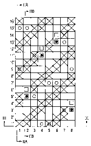
Example 1
FIG. 1 is a design diagram showing the complete design
of Example 1 of the present invention. FIGS. 2A and 2B are
cross-sectional views along the lines IIA-IIA and IIB-IIB
at the warps 1 and 2 of FIG. 1 respectively. FIG. 3 is a
cross-sectional view along the line III-III at the weft 1'
of FIG. 1 .
In the diagram of FIG. 1, warps indicated by 1, 3, 5
and 7, of eight pairs of an upper surface side warp and a
lower surface side warp arranged vertically, are pairs of
an upper surface side warp forming an upper surface side
surface and a lower surface side warp forming a lower
- 20 -
CA 02516882 2005-08-23
NFC-316
surface side surface arranged vertically, while warps
indicated by 2, 4, 6 and 8 are pairs of two warp binding
yarns which are woven with upper surface side wefts and
lower surface side wefts to form a portion of an upper
surface side surface design and a portion of a lower
surface side surface design. Wefts indicated by 1', 2',
3' ... 16' are upper surface side wefts and lower surface
side wefts. The lower surface side wefts are located below
the upper surface side wefts of the odd number 1', 3',
5', ... 15', meaning that their density is half of that of
the upper surface side wefts. The warp binding yarns weave
an upper surface side layer with a lower surface side layer
and they do not impair the surface design, because they
form each surface design while mutually complementing the
upper surface side surface design and lower surface side
surface design. A pair of two warp binding yarns and a pair
of an upper surface side warp and a lower surface side warp
are located alternately one by one. The lower surface side
wefts are arranged at a density half of the upper surface
side wefts.
A lower surface side warp has a 4/1-2/1 design in
which it passes over four successive lower surface side
wefts, passes under one lower surface side weft, passes
over two successive lower surface side wefts and passes
under one lower surface side weft. Described specifically,
a lower surface side warp 1 passes over four successive
lower surface side wefts 1', 3', 5' and 7', passes under a
lower surface side weft 9', passes over two successive
- 21 -
CA 02516882 2005-08-23
NFC-316
lower surface side wefts 11' and 13' and passes under a
lower surface side weft 15'.
One of warp binding yarns forming a pair is woven with
at least one upper surface side weft to form the upper
surface side surface design, below which the other warp
binding yarn is woven with one lower surface side weft,
while the one warp binding yarn is woven with one lower
surface side weft, over which the other warp binding yarn
is woven with at least one upper surface side weft to form
the upper surface side surface design. These warp binding
yarns cooperatively function as one warp constituting an
upper surface side complete design. The lower surface side
surface design is similar to the 4/1-2/1 design formed by a
lower surface side warp. One of warp binding yarns 2
forming a pair is woven with upper surface side wefts 5'
and 6', under which the other warp binding yarn is woven
with the lower surface side weft 5', while the one warp
binding yarn is woven with the lower surface side weft 15',
over which the other warp binding yarn is woven with upper
surface side wefts 9', 10', 13', 14', 1' and 2'. Thus, the
lower surface side surface has a 4/1-2/1 design and the
upper surface side surface has a 2/2 design. Warp binding
yarns as a pair thus mutually complement the upper surface
side surface design and the lower surface side surface
design and form each surface design. For example, one of
warp binding yarns 2 forms a design in which it passes over
the upper surface side wefts 1' and 2°, passes between
upper surface side wefts 3' and 4' and a lower surface side
- 22 -
CA 02516882 2005-08-23
NFC-316
weft, passes under the lower surface side weft 5', passes
between upper surface side wefts 6', 7', 8' and a lower
surface side weft, passes over the upper surface side wefts
9' and 10', passes between upper surface side wefts 11' and
12' and a lower surface side weft, passes over the upper
surface side wefts 13' and 14' and then passes between
upper surface side wefts 15' and 16' and a lower surface
side weft. The other one forms a design in which it passes
between the upper surface side wefts 1' to 4' and lower
surface side wefts, passes over the upper surface side
wefts 5' and 6', passes between upper surface side wefts 7'
to 14' and lower surface side wefts, passes under the lower
surface side weft 15' and then passes between the upper
surface side weft 16' and a lower surface side weft. The
pair of these two warp binding yarns cooperatively forms,
as the upper surface side surface design, a 2/2 design in
which they pass over two successive upper surface side
wefts and pass under two successive upper surface side
wefts, while they form, as the lower surface side surface
design, a 4/1-2/1 design in which they pass over four
successive lower surface side wefts, pass under one lower
surface side weft, pass over two successive lower surface
side wefts and then pass under one lower surface side weft.
The upper surface side surface design is similar to the 2/2
design formed by the other upper surface side warps and
upper surface side wefts, while the lower surface side
surface design is similar to the 4/1-2/1 design formed by
other lower surface side warps and lower surface side wefts.
- 23 -
CA 02516882 2005-08-23
NFC-316
In this Example, the warp binding yarn 2 is placed
while shifting the design of the lower surface side warp 1
by three lower surface side wefts. A lower surface side
warp 3 adjacent to the warp binding yarn 2 is also placed
while shifting the design of the warp binding yarn 2 by
three lower surface side wefts. By repeating this and
arranging them successively, a lower surface side warp and
a warp binding yarn which are adjacent to each other
simultaneously weave therein one lower surface side weft
from the lower surface side, whereby the resulting fabric
has improved rigidity. In addition, on the lower surface
side surface, a weft long crimp of a lower surface side
weft corresponding to six lower surface side warps is
formed so that the fabric has improved wear resistance.
By placing the lower surface side warp 1 and the warp
binding yarn 2 which are adjacent to each other while
shifting the design by three lower surface side wefts and
weaving the lower surface side weft 15' from the lower
surface side by the lower surface side warp 1 and warp
binding yarn 2 simultaneously, a design in which the lower
surface side weft 15' passes over two warps, that is, the
lower surface side warp 1 and warp binding yarn 2, and then
passes under six successive warps, that is, lower surface
side warps 3, 5, and 7 and warp binding yarns 4, 6 and 8 is
formed.
Simultaneous weaving of a lower surface side weft with
a lower surface side warp and a warp binding yarn brings
them close to each other. A lower surface side warp and a
- 24 -
CA 02516882 2005-08-23
NFC-316
warp binding yarn are woven with a lower surface side weft
twice. The lower surface side warp is woven once with each
of two warp binding yarns, which are adjacent thereto on
both sides, simultaneously so that it is arranged in a
zigzag manner while adjoining them alternately. The warp
binding yarn is also woven once with each of two lower
surface side warps, which are adjacent thereto on both
sides, simultaneously so that it is arranged in a zigzag
manner while adjoining them alternately. Accordingly, warp-
direction yarns constituting the lower surface side layer
are arranged in a zigzag manner.
The above-described arrangement in a zigzag manner
will next be described with lower surface side warp 3 and a
warp binding yarn 4 as examples. The warp binding yarn 2
and the lower surface side warp 3 are woven simultaneously
with the lower surface side weft 5', which brings the warp
binding yarn 2 and the lower surface side warp 3 close to
each other, while the lower surface side warp 3 and the
warp binding yarn 4 are woven simultaneously with the lower
surface side weft 11', which brings the lower surface side
warp 3 and warp binding yarn 4 close to each other. By this,
the lower surface side warp 3 gets close to the warp
binding yarn 2 at the intersection with the lower surface
side weft 5° and gets close to the warp binding yarn 4 at
the intersection with the lower surface side weft 11'. The
lower surface side warp is thus arranged in a zigzag manner
by repeating this.
The warp binding yarn 4 and the lower surface side
- 25 -
CA 02516882 2005-08-23
NFC-316
warp 5 are woven simultaneously by the lower surface side
weft 1', which brings the warp binding yarn 4 and lower
surface side warp 5 close to each other, while the lower
surface side warp 3 and warp binding yarn 4 are
simultaneously woven by the lower surface side weft 11',
which brings the lower surface side warp 3 and warp binding
yarn 4 closer to each other. By this, the warp binding yarn
4 gets close to the lower surface side warp 3 at the
intersection with the lower surface side weft 1' and gets
close to the lower surface side warp 5 at the intersection
with the lower surface side weft 11'. The lower surface
side warp is thus arranged in a zigzag manner by repeating
this. The other lower surface side warps and warp binding
yarns are also arranged in a zigzag manner while adjoining
yarns adjacent thereto alternately, suggesting that warp-
direction yarns constituting the lower surface side layer
are arranged in a zigzag manner. An overlapped portion and
a non-overlapped portion between a warp-direction yarn
constituting the upper surface side layer and a warp-
direction yarn constituting the lower surface side layer
are therefore caused to exist as a mixture by employing
such a zigzag arrangement. By this, the water drainage
property becomes uneven, which enables stepwise dehydration
and makes it possible to inhibit generation of dehydration
marks, sticking of a sheet raw material on a wire and loss
of fiber or filler, or to improve rigidity in an oblique
direction.
In the upper surface side layer, an upper surface side
- 26 -
CA 02516882 2005-08-23
NFC-316
warp has a 2/2 design in which it passes over two
successive upper surface side wefts, and then passes under
two successive upper surface side wefts. A warp binding
yarn adjacent to the upper surface side warp is formed by
shifting the design of the upper surface side warp by one
upper surface side weft and then repeating this
successively. Described specifically, the upper surface
side warp 1 is obtained by repeating a 2/2 design in which
the upper surface side warp 1 passes over two successive
upper surface side wefts 4' and 5' and then passes under
two successive upper surface side wefts 6' and 7'. The
upper surface side surface design formed by a pair of warp
binding yarns 2 is also a 2/2 design. The other upper
surface side warps and warp binding yarns also have a 2/2
design. A uniform surface can be formed by employing the
same design for the upper surface side surface design
formed by upper surface side warps and the upper surface
side surface design formed by warp binding yarns. In this
example, the upper surface side layer is formed into a 2/2
design but any design can be selected as needed.
By employing the above-described design of the present
invention, the resulting fabric is able to have improved
rigidity, oblique rigidity, wear resistance and surface
property, and in addition, generation of dehydration marks,
sticking of a sheet raw material on a wire and loss of
fiber or filler can be inhibited.
Example 2
FIG. 4 is a design diagram illustrating the complete
- 27 -
CA 02516882 2005-08-23
NFC-316
design of Example 2 of the present invention. FIGS. 5A and
5B are cross-sectional views along the lines VA-VA and VB-
VB at the warps 1 and 2 of FIG. 4 respectively. FIG. 6 is a
cross-sectional view along the line VI-VI at the weft 2' of
FIG. 4.
In the design diagram of FIG. 4, pairs of an upper
surface side warp and a lower surface side warp, of eight
pairs of an upper surface side warp and lower a surface
side warp vertically arranged, are indicated by 1, 3, 4, 5,
7, 8 and pairs of warp binding yarns are indicated by 2 and
6. The pairs of warp binding yarns and the pairs of an
upper surface side warp and a lower surface side warp are
arranged at a ratio of 1:3. Upper surface side wefts and
lower surface side wefts are arranged at a ratio of 3:2.
Similar to Example l, warp binding yarns are yarns for
weaving the upper surface side layer and lower surface side
layer. Warp binding yarns as a pair mutually complement
both the upper surface side surface design and the lower
surface side surface design so that they do not break the
surface design. Different from Example 1, the upper surface
side layer has a plain weave design so that the upper
surface side surface becomes denser than that of Example 1.
As a result, the fabric has improved rigidity, oblique
rigidity and surface property, and generation of
dehydration marks, sticking of a sheet raw material on a
wire, loss of fiber or filler can be inhibited.
Example 3
FIG. 7 is a design diagram illustrating the complete
- 28 -
CA 02516882 2005-08-23
NFC-316
design of Example 3 of the present invention. FIGS. 8A and
8B are cross-sectional views along the lines VIIIA-VIIIA
and VIIIB-VIIIB at the warps 1 and 2 of FIG. 7 respectively.
FIG. 9 is a cross-sectional view along the line IX-IX at
the weft 2' of FIG. 7.
In the diagram of FIG. 7, pairs of an upper surface
side warp and a lower surface side warp, of eight pairs of
an upper surface side warp and a lower surface side warp
vertically arranged, are indicated by 1, 3, 4, 5, 7, 8 and
pairs of warp binding yarns are indicated by 2 and 6. The
pairs of warp binding yarns and the pairs of an upper
surface side warp and a lower surface side warp are
arranged at a ratio of 1:3. Upper surface side wefts and
lower surface side wefts are arranged at a ratio of 1:1.
The upper surface side layer has a 1/3 design so that a
long crimp appears in the weft direction on the upper
surface side. This improves fiber supporting property.
Employment of broken twill weave breaks the regularity in
an oblique direction of the upper surface side surface
design, which makes it possible to suppress generation of
wire marks in an oblique direction.
Example 4
FIG. 10 is a design diagram illustrating the complete
design of Example 4 of the present invention. FIGS. 11A and
11B are cross-sectional views along the lines XIA-XIA and
XIB-XIB at the warps 1 and 2 of FIG. 10 respectively. FIG.
12 is a cross-sectional view along the line XII-XII at the
weft 1' of FIG. 10.
- 29 -
CA 02516882 2005-08-23
NFC-316
In the diagram of FIG. 10, pairs of an upper surface
side warp and a lower surface side warp, of eight pairs of
an upper surface side warp and a lower surface side warp
vertically arranged, are indicated by 1, 3, 4, 5, 7, 8 and
pairs of warp binding yarns are indicated by 2 and 6. The
pairs of warp binding yarns and the pairs of an upper
surface side warp and a lower surface side warp are
arranged at a ratio of 1:3. Upper surface side wefts and
lower surface side wefts are arranged at a ratio of 2:1.
The upper surface side layer has a 1/3 design so that a
long crimp appears in the weft direction on the upper
surface side. This improves fiber supporting property.
Example 5
FIG. 13 is a design diagram illustrating the complete
design of Example 5 of the present invention. FIGS. 14A and
14B are cross-sectional views along the lines XIVA-XIVA and
XIVB-XIVB at the warps 1 and 2 of FIG. 13 respectively. FIG.
15 is a cross-sectional view along the line XV-XV at the
weft 3' of FIG. 13.
In the design diagram of FIG. 13, pairs of an upper
surface side warp and a lower surface side warp, of eight
pairs of an upper surface side warp and a lower surface
side warp vertically arranged, are indicated by l, 3, 5,
and 7 and pairs of warp binding yarns are indicated by 2, 4,
6 and 8. The pairs of two warp binding yarns and the pairs
of an upper surface side warp and a lower surface side warp
are arranged alternately. Upper surface side wefts and
lower surface side wefts are arranged at a ratio of 2:1.
- 30 -
CA 02516882 2005-08-23
NFC-316
The upper surface side layer employs a 2/2 design and
broken twill weave, which makes it possible to break the
regularity of the upper surface side surface design in an
oblique direction, thereby inhibiting the generation of
wire marks.
Example 6
FIG. 16 is a design diagram illustrating the complete
design of Example 6 of the present invention. FIGS. 17A and
17B are cross-sectional views along the line XVIIA-XVIIA
and XVIIB-XVIIB at the warps 1 and 2 of FIG. 16
respectively. FIG. 18 is a cross-sectional view along the
line XVIII-XVIII at the weft 1' of FIG. 16.
In the design diagram of FIG. 16, pairs of an upper
surface side warp and a lower surface side warp, of eight
pairs of an upper surface side warp and a lower surface
side warp vertically arranged, are indicated by 1, 3, 5,
and 7 and pairs of warp binding yarns are indicated by 2, 4,
6 and 8. The pairs of two warp binding yarns and the pairs
of an upper surface side warp and a lower surface side warp
are arranged alternately. Upper surface side wefts and
lower surface side wefts are arranged at a ratio of 2:1.
The warp binding yarn of the upper surface side layer forms
a 2/2 design, while the upper surface side warp forms a
plain weave design. Thus, the upper surface side layer is
composed of two warp complete designs. Adoption of two warp
complete designs makes it possible to break the regularity
of the upper surface side surface design in an oblique
direction and inhibits the generation of wire marks in an
- 31 -
CA 02516882 2005-08-23
NFC-316
oblique direction.
Example 7
FIG. 19 is a design diagram illustrating the complete
design of Example 7 of the present invention. FIGS. 20A and
20B are cross-sectional views along the lines XXA-XXA and
XXB-XXB at the warps 1 and 2 of FIG. 19 respectively. FIG.
21 is a cross-sectional view along the line XXI-XXI at the
weft 2' of FIG. 19.
In the diagram of FIG. 19, pairs of an upper surface
side warp and a lower surface side warp, of eight pairs of
an upper surface side warp and a lower surface side warp
vertically arranged, are indicated by 1, 3, 4, 5, 7, 8 and
pairs of warp binding yarns are indicated by 2 and 6. The
pairs of warp binding yarns and the pairs of an upper
surface side warp and a lower surface side warp are
arranged at a ratio of 1:3. Upper surface side wefts and
lower surface side wefts are arranged at a ratio of 3:2.
The upper surface side layer is formed with a plain weave
design so that the upper surface side surface becomes
denser than that of Example 1. As a result, the fabric has
improved rigidity, oblique rigidity and surface property,
and generation of dehydration marks, sticking of a sheet
raw material on a wire, loss of fiber or filler can be
inhibited. In this example, the recess formed in the
surface by the warp binding yarn is small so that the
fabric has good surface property. For example, in Example 2,
a warp binding yarn 2 weaves therein a lower surface side
weft 1' from the lower surface side, and then weaves
- 32 -
CA 02516882 2005-08-23
NFC-316
therein an upper surface side weft 3', thereby binding the
upper surface side layer and the lower surface side layer.
In this Example 7, a warp binding yarn 2 weaves therein a
lower surface side weft 1' from the lower surface side and
then weaves therein an upper surface side weft 5', thereby
binding the two layers. In the latter case, the weaving
positions of the upper surface side weft and the lower
surface side weft are more distant than those of Example 2.
The upper surface side layer and lower surface side layer
are therefore bound while forming a gentle slope. The
recess formed in the surface by the warp binding yarn is
smaller and surface property is better, compared with those
of Example 2.
Example 8
FIG. 22 is a design diagram illustrating the complete
design of Example 8 of the present invention. FIGS. 23A and
23B are cross-sectional views along the lines XXIIIA-XXIIIA
and XXIIIB-XXIIIB at the warps 1 and 2 of FIG. 22
respectively. FIG. 24 is a cross-sectional view along the
line XXIV-XXIV at the weft 1' of FIG. 22.
In the diagram of FIG. 22, pairs of an upper surface
side warp and a lower surface side warp, of eight pairs of
an upper surface side warp and a lower surface side warp
vertically arranged, are indicated by 1, 3, 4, 5, 7, 8 and
pairs of warp binding yarns are indicated by 2 and 6. The
pairs of warp binding yarns and the pairs of upper surface
side warp and lower surface side warp are arranged at a
ratio of 1:3. Upper surface side wefts and lower surface
- 33 -
CA 02516882 2005-08-23
NFC-316
side wefts are arranged at a ratio of 2:1. Adoption of a
1/3 design and broken twill weave for its upper surface
side layer makes it possible to break the regularity of the
upper surface side surface design in an oblique direction,
thereby inhibiting generation of wire marks in an oblique
direction.
Example 9
FIG. 25 is a design diagram illustrating the complete
design of Example 9 of the present invention. FIGS. 26A and
26B are cross-sectional views along the lines XXVIA-XXVIA
and XXVIB-XXVIB at the warps 1 and 2 of FIG. 25
respectively. FIG. 27 is a cross-sectional view along the
line XXVII-XXVII at the weft 4' of FIG. 25.
In the diagram of FIG. 25, pairs of an upper surface
side warp and a lower surface side warp, of eight pairs of
an upper surface side warp and a lower surface side warp
vertically arranged, are indicated by 1, 3, 4, 5, 7, 8 and
pairs of warp binding yarns are indicated by 2 and 6. The
pairs of warp binding yarns and the pairs of an upper
surface side warp and a lower surface side warp are
arranged at a ratio of 1:3. Upper surface side wefts and
lower surface side wefts are arranged at a ratio of 3:2.
The upper surface side layer is formed with a plain weave
design so that it becomes denser than that of Example 1. As
a result, the fabric has improved rigidity, oblique
rigidity and surface property, and generation of
dehydration marks, sticking of a sheet raw material on a
wire, loss of fiber or filler can be inhibited.
- 34 -
CA 02516882 2005-08-23
NFC-316
Example 10
FIG. 28 is a design diagram illustrating the complete
design of Example 10 of the present invention. FIGS. 29A
and 29B are cross-sectional views along the lines XXIXA-
XXIXA and XXIXB-XXIXB at the warps 1 and 2 of FIG. 28
respectively. FIG. 30 is a cross-sectional view along the
line XXX-XXX at the weft 1' of FIG. 28.
In the diagram of FIG. 28, pairs of an upper surface
side warp and a lower surface side warp, of eight pairs of
an upper surface side warp and a lower surface side warp
vertically arranged, are indicated by 1, 3, 4, 5, 7, 8 and
pairs of a warp binding yarn and a lower surface side warp
are indicated by 2 and 6. In the pair of a warp binding
yarn and a lower surface side warp, the warp binding yarn
is woven with an upper surface side weft on the upper
surface side surface and functions as one warp constituting
the upper surface side complete design, while, on the lower
surface side, the warp binding yarn and the lower surface
side warp cooperatively form a lower surface side surface
design similar to that formed by the other lower surface
side warp. The pairs of a warp binding yarn and a lower
surface side warp and the pairs of an upper surface side
warp and a lower surface side warp are arranged at a ratio
of 1:3. Upper surface side wefts and lower surface side
wefts are arranged at a ratio of 1:1. In Examples 1 to 9,
at least one pair of warp binding yarns is located in the
complete design. In the fabric of this Example, on the
other hand, not a pair of warp binding yarns but two pairs
- 35 -
CA 02516882 2005-08-23
NFC-316
of a warp binding yarn and a lower surface side warp are
arranged. Such a pair of a warp binding yarn and a lower
surface side warp also exhibits sufficient binding strength.
Example 11
FIG. 31 is a design diagram illustrating the complete
design of Example 12 of the present invention. FIGS. 32A
and 32B are cross-sectional views along the line XXXIIA-
XXXIIA and XXXIIB-XXXIIB at the warps 1 and 2 of FIG. 31
respectively. FIG. 33 is a cross-sectional view along the
line XXXIII-XXXIII at the weft 2° of FIG. 31.
In the diagram of FIG. 31, pairs of an upper surface
side warp and a lower surface side warp, of eight pairs of
an upper surface side warp and a lower surface side warp
vertically arranged, are indicated by 1, 3, 4, 5, 7, 8 and
pairs of a warp binding yarn and an upper surface side warp
are indicated by 2 and 6. In the pair of a warp binding
yarn and an upper surface side warp, the warp binding yarn
and upper surface side warp are woven with respective upper
surface side wefts on the upper surface side surface and
cooperatively function as one warp constituting an upper
surface side complete design, while on the lower surface
side, the warp binding yarn forms a lower surface side
surface design similar to that of a lower surface side warp.
The pairs of a warp binding yarn and an upper surface side
warp and the pairs of an upper surface side warp and a
lower surface side warp are arranged at a ratio of 1:3.
Upper surface side wefts and lower surface side wefts are
arranged at a ratio of 1:1. In this Example, not a pair of
- 36 -
CA 02516882 2005-08-23
NFC-316
warp binding yarns but two pairs of a warp binding yarn and
a lower surface side warp are arranged. Such a pair of a
warp binding yarn and an upper surface side warp also
exhibits sufficient binding strength.
The present invention prevents generation of
dehydration marks, sticking of fibers on a wire and loss of
fibers. Such a fabric has excellent utility as a
papermaking wire.
Although only some exemplary embodiments of this
invention have been described in detail above, those
skilled in the art will readily appreciated that many
modifications are possible in the exemplary embodiments
without materially departing from the novel teachings and
advantages of this invention. Accordingly, all such
modifications are intended to be included within the scope
of this invention.
- 37 -