Sélection de la langue

Search

Sommaire du brevet 2518838 

Énoncé de désistement de responsabilité concernant l'information provenant de tiers

Une partie des informations de ce site Web a été fournie par des sources externes. Le gouvernement du Canada n'assume aucune responsabilité concernant la précision, l'actualité ou la fiabilité des informations fournies par les sources externes. Les utilisateurs qui désirent employer cette information devraient consulter directement la source des informations. Le contenu fourni par les sources externes n'est pas assujetti aux exigences sur les langues officielles, la protection des renseignements personnels et l'accessibilité.

Disponibilité de l'Abrégé et des Revendications

L'apparition de différences dans le texte et l'image des Revendications et de l'Abrégé dépend du moment auquel le document est publié. Les textes des Revendications et de l'Abrégé sont affichés :

  • lorsque la demande peut être examinée par le public;
  • lorsque le brevet est émis (délivrance).
(12) Demande de brevet: (11) CA 2518838
(54) Titre français: MECANISME DE DIRECTION POUR BROUETTE
(54) Titre anglais: STEERING MECHANISM FOR WHEELBARROW
Statut: Réputée abandonnée et au-delà du délai pour le rétablissement - en attente de la réponse à l’avis de communication rejetée
Données bibliographiques
Abrégés

Abrégé anglais


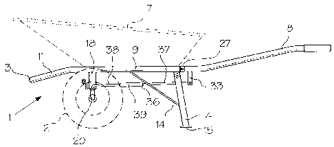
A steerable wheelbarrow includes a pair of handles rotatably connected to the
rear end of the frame of the wheelbarrow for rotation around a horizontal
axis, and a
pair of linkages connecting the handles to L-shaped, wheel carrying axles,
which are
interconnected by a separate linkage, whereby rotation of the handles in
opposite
directions around the horizontal axis results in rotation of the axles around
parallel,
vertical axes to turn the wheelbarrow. A stop mechanism limits turning of the
wheels to
decrease the likelihood of tipping during turning.

Revendications

Note : Les revendications sont présentées dans la langue officielle dans laquelle elles ont été soumises.


CLAIMS:
1. A wheelbarrow comprising:
a frame;
a container on the frame for carrying a load;
a pair of axles proximate a front end of the frame rotatable around vertical
axes
relative to the frame;
a pair of spaced apart handles extending rearwardly from and pivotally
connected to the rear of the frame for independent rotation around a
horizontal axis;
first levers extending downwardly from said handles;
second levers on said axles for rotating the axles around said vertical axes;
a pair of first linkages connecting said first and second levers; and
a second linkage interconnecting said pair of axles, whereby rotation of said
handles in opposite directions around said horizontal axis results in rotation
of both said
axles around said vertical axes.
2. The wheelbarrow of claim 1, including a stop assembly for limiting rotation
of said axles during turning of the wheelbarrow.
3. The wheelbarrow of claim 2, wherein said stop assembly includes a pin
extending forwardly from said second linkage beneath said frame, a crossbar
suspended from said frame, and a pair of spaced apart posts on said crossbar
for
engagement by said pin when the wheelbarrow is turned by a predetermined limit
in
either of two directions.
4. The wheelbarrow of claim 1, wherein said first linkage includes first and
second rods connected to one said first lever and to one said second lever,
6

coupler for connecting said rods end-to-end, whereby the length of said first
linkage and
the orientation of free ends of the rods can be adjusted.
5. The wheelbarrow of claim 1, including a pair of spaced apart sleeves
extending
downwardly from said frame for rotatably receiving said axles for rotation
around said
vertical axes.
6. The wheelbarrow of claim 5, wherein each said axle is L-shaped, including
a vertical arm rotatable in one said sleeve, and a horizontal arm for
supporting a wheel.
7. The wheelbarrow of claim 5, wherein said second linkage includes third
levers on said axles perpendicular to said second levers, and a cross arm
extending
between and rotatably connected to said third levers.
7

Description

Note : Les descriptions sont présentées dans la langue officielle dans laquelle elles ont été soumises.


CA 02518838 2005-09-12
STEERING MECHANISM FOR WHEELBARROW
BACKGROUND OF THE INVENTION
FIELD OF THE INVENTION
This invention relates to a wheelbarrow and, in particular, to a wheelbarrow
having a novel steering mechanism.
DISCUSSION OF THE PRIOR ART
As described in the Bisaillon US Patent No. 5,924,708, issued July 20, 1999,
in
general, conventional wheelbarrows are difficult to steer, particularly when
filled with a
heavy load. When using a single wheeled vehicle, tipping is a common
occurrence
when turning. The use of two wheels on a wheelbarrow makes the device move
stable,
but does not solve the turning problems. The second paragraph of the above-
referenced Bisaillon US patent lists several references disclosing steering
mechanisms
for small carts and the like. The apparatus described by the Bisaillon patent
provides a
solution to the problem. However, in terms of structural simplicity the
existing apparatus
could use improvement, particularly if the steering mechanism is to be
retrofitted to an
existing vehicle.
The object of the present invention is to provide a wheelbarrow having a
relatively simple steering mechanism, which facilitates construction of the
wheelbarrow
and retrofitting existing vehicles.
Accordingly, the invention relates to a wheelbarrow comprising:
a frame;
a container on the frame for carrying a load;
a pair of axles proximate a front end of the frame rotatable around vertical
axes
relative to the frame;
1

CA 02518838 2005-09-12
a pair of spaced apart handles extending rearwardly from and pivotally
connected to the rear of the frame for independent rotation around a
horizontal axis;
first levers extending downwardly from said handles;
second levers on said axles for rotating the axles around said vertical axes;
a pair of first linkages connecting said first and second levers; and
a second linkage interconnecting said pair of axles, whereby rotation of said
handles in opposite directions around said horizontal axis results in rotation
of both said
axles around said vertical axes.
BRIEF DESCRIPTION OF THE DRAWINGS
The invention is described below in greater detail with reference to the
drawings,
wherein:
Figure 1 is a side view of a wheelbarrow incorporating a preferred embodiment
of
the steering mechanism of the present invention;
Figure 2 is a front view of the wheelbarrow and steering mechanism of Fig. 1;
Figure 3 is a perspective view of all but the front end of a frame used in the
wheelbarrow of Figs. 1 and 2 as seen from below;
Figure 4 is an isometric view of an axle assembly used in the steering
mechanism as viewed from below;
Figure 5 is an isometric view of the rear end of the frame of the wheelbarrow
of
Figs. 1 and 2; and
Figure 6 is a rear view of the steering mechanism of Figs. 1 and 2.
With reference to the drawings, the wheelbarrow of the present invention
includes a frame indicated generally at 1 supported by a pair of wheels 2
proximate the
front end 3 and legs 4 at the rear end 5. A conventional container 7 is
mounted on the
2

CA 02518838 2005-09-12
frame 1 for carrying a load. A pair of handles 8 extend rearwardly from the
frame 1 for
lifting the rear end 5 of the frame. In the case of the present invention, the
handles 8
are also used to steer the wheelbarrow.
As best shown in Figs. 2 and 3, the frame 1 is defined by a pair of parallel,
tubular sides 9 interconnected at their rear ends by a flat plate 10. The
front ends 11 of
the sides 9 slope downwardly and are interconnected by a crossbar 12, which is
integral
with the sides. The crossbar 12 acts as a fulcrum when the wheelbarrow is
tilted
around the axis of the wheels 2 during a dumping operation. The legs 4 extend
downwardly and slightly rearwardly from the rear ends of the sides 9. Diagonal
braces
14 extend between the sides 9 and the legs 4. Flat plates defining feet 15 are
provided
on the bottom ends of the legs 4. The frame 1 is reinforced by a crossbar 16
near the
inclined front ends 11 of the sides 9. The crossbar 16 also supports the
container 7.
A sleeve 18 extends downwardly from each of the sides 9 near the location of
the crossbar 16 for rotatably receiving the vertical arm 19 of a generally L-
shaped axle
assembly 20 (Fig. 4). An annular flange 21 on the vertical arm 19 of the axle
assembly
limits movement of the axle assembly 20 into the sleeve 18. A second flange 24
on
the horizontal arm or axle 25 of the assembly 20 limits movement of a wheel 2
onto the
axle, i.e. positions the wheel on the axle. A hole 26 is provided in the outer
end of the
axle 25 of each assembly 20 for receiving a cotter pin (not shown) which
retains a wheel
20 2 on the axle.
The wheelbarrow is steered using a steering mechanism, which includes the
handles 8. As best shown in Fig. 5, the handles 8 are pivotally mounted on the
plate 10
defining the rear end of the frame 1. For such purpose a pair of spaced apart
clevis-like
brackets 27 are mounted on the plate 10 at the ends thereof. A transversely
extending
3

CA 02518838 2005-09-12
sleeve 29 on the front end of each handle 8 containing a bushing (not shown)
is
rotatably retained in the bracket 27 by a bolt 30 and a nut 32. A lever 33
extending
downwardly from the front end of each handle 8 is connected to a second lever
34
welded to the vertical arm of an axle assembly 20 near the corner thereof by a
linkage
36. Each linkage 36 is defined by a pair of rods 37 and 38 connected end-to-
end by an
internally threaded coupler 39, which permits adjustments to the length of the
linkage.
The L-shaped end of one rod 36 is connected to the lever 33 by a cotter pin
40. The L-
shaped end of the other rod 38 is connected to the lever 34 by a cotter pin
42.
Another, generally S-shaped lever 43, which is perpendicular to the lever 34,
extends forwardly and upwardly from each axle assembly 20, i.e. towards the
front end
of the wheelbarrow. The levers 34 are interconnected by a second linkage 44
defined
by a cross arm pivotally connected to the levers 43 by straight pins 45 and
cotter pins
46. With this arrangement, rotation of the one axle assembly 20 around the
longitudinal
axis of the sleeve 18 results in a simultaneous corresponding rotation of the
other axle
assembly to cause turning of the wheels 2 in unison. The amount by which the
wheels
2 can be turned is limited by stops in the form of a pair of spaced apart
posts 48
mounted on a crossbar 49 extending between the bottom ends of the sleeves 18,
and a
pin 50 extending rearwardly from the center of the cross arm 44 between the
posts 48.
W hen the arm 44 moves sufficiently laterally with respect to the wheelbarrow
frame 1,
the pin 50 encounters one of the stop posts 48. The spacing between the posts
48
dictates the minimum turning radius of the wheelbarrow. The stop assembly
reduces
the likelihood of tipping during turning of the wheelbarrow.
In operation, with the handles 8 at the same level, the wheelbarrow will
travel
along a straight line. By lifting on one handle 8 and/or pushing down on the
other
4

CA 02518838 2005-09-12
handle 8, the arrangement of the Levers 33, 34 and 43, and the linkages 36 and
44
cause the wheels 2 to rotate in unison around parallel horizontal axes so that
the
wheelbarrow turns smoothly. The use of levers and linkages directly connecting
each
handle 8 to one axle 25 makes turning of the wheelbarrow relatively easy. The
stop
posts 48 on the crossbar 49 and the pin 50 on the linkage 44 reduce the amount
by
which the wheels 2 can be turned to reduce the likelihood of tipping.
5

Dessin représentatif
Une figure unique qui représente un dessin illustrant l'invention.
États administratifs

2024-08-01 : Dans le cadre de la transition vers les Brevets de nouvelle génération (BNG), la base de données sur les brevets canadiens (BDBC) contient désormais un Historique d'événement plus détaillé, qui reproduit le Journal des événements de notre nouvelle solution interne.

Veuillez noter que les événements débutant par « Inactive : » se réfèrent à des événements qui ne sont plus utilisés dans notre nouvelle solution interne.

Pour une meilleure compréhension de l'état de la demande ou brevet qui figure sur cette page, la rubrique Mise en garde , et les descriptions de Brevet , Historique d'événement , Taxes périodiques et Historique des paiements devraient être consultées.

Historique d'événement

Description Date
Exigences relatives à la révocation de la nomination d'un agent - jugée conforme 2020-09-01
Demande non rétablie avant l'échéance 2012-09-12
Le délai pour l'annulation est expiré 2012-09-12
Réputée abandonnée - omission de répondre à un avis sur les taxes pour le maintien en état 2011-09-12
Modification reçue - modification volontaire 2010-09-28
Lettre envoyée 2010-09-08
Toutes les exigences pour l'examen - jugée conforme 2010-08-30
Exigences pour une requête d'examen - jugée conforme 2010-08-30
Requête d'examen reçue 2010-08-30
Demande publiée (accessible au public) 2007-03-12
Inactive : Page couverture publiée 2007-03-11
Inactive : CIB en 1re position 2006-04-07
Inactive : CIB attribuée 2006-04-07
Lettre envoyée 2005-11-24
Inactive : Transfert individuel 2005-10-27
Inactive : Lettre de courtoisie - Preuve 2005-10-25
Demande reçue - nationale ordinaire 2005-10-21
Inactive : Certificat de dépôt - Sans RE (Anglais) 2005-10-21
Déclaration du statut de petite entité jugée conforme 2005-09-12

Historique d'abandonnement

Date d'abandonnement Raison Date de rétablissement
2011-09-12

Taxes périodiques

Le dernier paiement a été reçu le 2010-08-30

Avis : Si le paiement en totalité n'a pas été reçu au plus tard à la date indiquée, une taxe supplémentaire peut être imposée, soit une des taxes suivantes :

  • taxe de rétablissement ;
  • taxe pour paiement en souffrance ; ou
  • taxe additionnelle pour le renversement d'une péremption réputée.

Les taxes sur les brevets sont ajustées au 1er janvier de chaque année. Les montants ci-dessus sont les montants actuels s'ils sont reçus au plus tard le 31 décembre de l'année en cours.
Veuillez vous référer à la page web des taxes sur les brevets de l'OPIC pour voir tous les montants actuels des taxes.

Historique des taxes

Type de taxes Anniversaire Échéance Date payée
Taxe pour le dépôt - petite 2005-09-12
Enregistrement d'un document 2005-10-27
TM (demande, 2e anniv.) - petite 02 2007-09-12 2007-08-17
TM (demande, 3e anniv.) - petite 03 2008-09-12 2008-09-04
TM (demande, 4e anniv.) - petite 04 2009-09-14 2009-09-09
Requête d'examen - petite 2010-08-30
TM (demande, 5e anniv.) - petite 05 2010-09-13 2010-08-30
Titulaires au dossier

Les titulaires actuels et antérieures au dossier sont affichés en ordre alphabétique.

Titulaires actuels au dossier
LES ACIERS ROBOND INC.
Titulaires antérieures au dossier
MICHEL BEAUDOIN
Les propriétaires antérieurs qui ne figurent pas dans la liste des « Propriétaires au dossier » apparaîtront dans d'autres documents au dossier.
Documents

Pour visionner les fichiers sélectionnés, entrer le code reCAPTCHA :


Pour visualiser une image, cliquer sur un lien dans la colonne description du document. Pour télécharger l'image (les images), cliquer l'une ou plusieurs cases à cocher dans la première colonne et ensuite cliquer sur le bouton "Télécharger sélection en format PDF (archive Zip)" ou le bouton "Télécharger sélection (en un fichier PDF fusionné)".

Liste des documents de brevet publiés et non publiés sur la BDBC .

Si vous avez des difficultés à accéder au contenu, veuillez communiquer avec le Centre de services à la clientèle au 1-866-997-1936, ou envoyer un courriel au Centre de service à la clientèle de l'OPIC.


Description du
Document 
Date
(aaaa-mm-jj) 
Nombre de pages   Taille de l'image (Ko) 
Abrégé 2005-09-11 1 15
Description 2005-09-11 5 182
Revendications 2005-09-11 2 51
Dessins 2005-09-11 5 89
Dessin représentatif 2007-02-19 1 9
Courtoisie - Certificat d'enregistrement (document(s) connexe(s)) 2005-11-23 1 106
Certificat de dépôt (anglais) 2005-10-20 1 158
Rappel de taxe de maintien due 2007-05-14 1 109
Rappel - requête d'examen 2010-05-12 1 119
Accusé de réception de la requête d'examen 2010-09-07 1 179
Courtoisie - Lettre d'abandon (taxe de maintien en état) 2011-11-06 1 173
Correspondance 2005-10-20 1 26
Taxes 2007-08-16 1 31
Taxes 2008-09-03 1 24
Taxes 2010-08-29 1 200