Note : Les descriptions sont présentées dans la langue officielle dans laquelle elles ont été soumises.
CA 02519067 2005-09-13
WO 2004/081276 PCT/BR2004/000029
SYSTEM AND PROCESS FOR DETECTING A LOAD OF CLOTHES IN
AN AUTOMATIC LAUNDRY MACHINE
Field of the Invention
The present invention refers to a system to be applied
to automatic laundry machines, which allows detecting
a load of clothes put into the laundry machine and
automatically selecting the level of the washing
liquid to be supplied to the machine according to the
washing program selected by the user.
The invention further relates to a process for
detecting a load of clothes put into the laundry
machine and for automatically selecting the level of
the washing liquid to be supplied to the machine, as a
function of the detected load of clothes.
Prior Art
There are known different systems for detecting a load
of clothes put into a laundry machine and thus
defining and controlling, automatically, the amount of
the washing liquid, generally water, to be supplied to
the machine, more precisely to the tub inside which is
seated a basl~.et designed to contain the load of
clothes and which is rotatively driven, upon the spin
operation, by an electric motor which also drives an
agitator provided in the interior of the basket.
One of such known detecting systems is described in
Patent US 5,515,565, which uses a height sensing means
to detect the height of the load of clothes placed
into the basket. An electronic control unit, which is
operatively associated with the height sensing means
of the load of clothes, processes the signal coming
from the height sensing means and which is
representative of the height of the load of clothes,
so as to determine the adequate level of the washing
liquid to be admitted into the tub and to control the
operation of a washing liquid inlet device, in order
CA 02519067 2005-09-13
WO 2004/081276 PCT/BR2004/000029
2
to maintain the latter opened, until a level sensing
means detects the obtainment of the washing liquid
level determined by the control unit.
In a preferred form, the height sensing means
comprises means for transmitting and receiving sonic
pulses that act on the load of clothes within the
basket under rotation. While adequately operating,
this prior art system requires complex expensive means
and constructions.
l0 Another known system is disclosed in Patent US
6,460,381. In this solution, a pressure sensor is
provided, mounted jointly with the suspension of the
tub and which is constructed so as to have its
magnetic characteristics altered as a function of the
stresses to which it is subjected. The variations of
the magnetic characteristics are converted in
inductance variations in a coil, generating
oscillating signals whose frequency varies as a
function of the inductance, allowing detecting the
load on the sensor. Thus, the load of clothes placed
in the laasl~et can be determined, as well as the load
of the washing liquid to be subsequently supplied to
the tub of the machine, and the clothes-washing liquid
total load is converted into a corresponding adequate
level of the washing liquid. Upon reaching the desired
level, the supply of the washing liquid is
automatically interrupted by actuation of an
electronic control unit.
This type of prior art system may present mechanical
errors produced during manufacture or have the weight
sensor located in an inadequate position, impairing
the accuracy in detecting the weight of both the
clothes and the washing liquid, resulting in washing
operations presenting an amount of water out of the
desirable standards.
CA 02519067 2005-09-13
WO 2004/081276 PCT/BR2004/000029
3
Still another known prior art system is described in
Patent US 4,862,710. This prior system uses a load
detecting means in the motor to detect an electrical
value representative of a rise characteristic of the
motor, which varies in accordance with a load acting
on a motor which drives the movable washing means of
the machine. During the spin cycle of the machine, the
time in which the value detected by the load detector
reaches a second reference value is measured, from a
first reference value.
The time measured is converted in the value of the
clothes-washing liquid total load inside the tub of
the machine. In this solution, the first and the
second reference values are voltage values measured in
the load detector, and the time the motor takes in the
spin cycle, to provoke a rise in the voltage and
reference values, is associated with a certain level
of load of clothes within the basket.
This prior art solution uses the voltage rise time
between two reference values, which are corrected as a
function of the supply voltage, to determine the load
of clothes in the basket and the corresponding
operational parameters of the machine in the
subsequent operations.
While allowing a certain accuracy in detecting the
load of clothes, this prior art solution presents the
inconvenience of requiring relatively complex
electronic circuits and of not considering the load
represented by the friction of the movable parts of
the machine, which load varies as a function of the
tolerances and of the manufacture and assembly methods
of the different components.
Besides the inconveniences above, the prior art
solution cited above is subjected to measurement
deviations due to the noises produced in the power
CA 02519067 2005-09-13
WO 2004/081276 PCT/BR2004/000029
4
source as a function of the voltage variations, which
can be intense and frequent. This prior art system
does not present a satisfactory accuracy in terms of
detecting the load of clothes, particularly when the
machine is installed in electric power sources that
are subjected to high noise levels.
Objects of the Invention
By reason of the inconveniences and deficiencies of
the prior art system for detecting the load of
clothes, it is an object of the present invention to
provide a system for detecting a load of clothes in an
automatic laundry machine, which presents a simple
construction of relatively low cost, and high accuracy
in detecting the load of clothes placed inside the
basl~et of the machine .
It is a further object of the present invention to
provide a system for detecting a load of clothes as
mentioned above, which allows determining,
automatically, the level of the washing liquid to be
supplied to the tub of the machine as a function of
the detected load of clothes.
It is still a further obj ect of the present lnVentlon
to provide a process for detecting a load of clothes
in an automatic machine, which permits obtaining,
accurately, through simple means of relatively low
cost, a signal representative of a load of clothes put
into the basket of the machine and which determines
the level of the washing liquid to be supplied to the
machine.
Disclosure of the Invention
The system for detecting a load of clothes of the
present invention is designed to be applied to an
automatic laundry machine of the type which comprises
a tub, a basket mounted in the interior of the tub and
which is dimensioned to receive a load of clothes to
CA 02519067 2005-09-13
WO 2004/081276 PCT/BR2004/000029
be washed, and an electric motor, which rotatively
drives the basket in a spin cycle to be executed by
the machine.
According to the invention, the present system
5 comprises a voltage sensor to detect the value of the
voltage supplied to the electric motor; a rotation
sensor, operatively associated with the electric motor
to detect the rotation of the latter; and a Control
unit, operatively associated with a timer, with the
voltage sensor, and with the rotation sensor, and
which is supplied, in a presetting step of the
machine, with data representative of the medium torque
of the electric motor in different voltage ranges, and
with data representative of the acceleration and
deceleration reference times of the electric motor
with the basket in the unloaded Condition, between two
distinct and predetermined rotation values of the
electric motor, in order to Calculate the reference
moment of inertia of the unloaded basket, said control
unit receiving, selectively, at the beginning of each
operation of the machine, data representative of the
acceleration and deceleration operation times of the
electric motor, with the basket Containing a load of
Clothes, between said rotation values of the electric
motor, and processing the data representative of the
medium torque of the electric motor in the voltage
range detected by the voltage sensor, and the data of
the reference and operation times, in order to
determine the moment of inertia of the basket with the
load of clothes and the difference of said moments of
inertia of the basket, and to produce a signal
representative of the mass of the load of Clothes.
The system mentioned above allows, through the
provision of the voltage and rotation sensors and by
providing the control unit with a timer, establishing
CA 02519067 2005-09-13
WO 2004/081276 PCT/BR2004/000029
6
reference data adjusted for each machine in the
manufacturing phase, and operational data related to
each load of clothes put into the basket, the
processing of said data allowing comparing the
respective moments of inertia and thence produce a
signal which represents, with high accuracy, the load
of clothes inserted in the basket and which will be
washed, independently of the voltage variations of the
power source of the electric motor.
In a particular application of the invention, the
signal representative of the load of clothes is
associated with a washing liquid level which, when
reached, makes the control unit produce a blocking
signal to an inlet valve means, interrupting the
supply of the washing liquid to the machine.
The invention further relates to a process for
detecting the load of clothes in an automatic laundry
machine of the type defined above, comprising the
following steps:
- rotatively driving the electric motor with the
basket unloaded, maintaining its energization until a
maximum rotation has been reached, the electric motor
being then de-energized and decelerated to a reduced
rotation value, as a function of the friction between
the movable parts;
- detecting the rotation of the electric motor in two
distinct and predetermined rotation values, which are
lower than the maximum rotation value, both in the
acceleration phase and the deceleration phase;
- measuring the acceleration and deceleration
reference times of the electric motor between said
distinct and predetermined rotation values;
- calculating a reference moment of inertia of the
unloaded basket, in a step of presetting the machine
to a posterior operation, by processing, in a control
CA 02519067 2005-09-13
WO 2004/081276 PCT/BR2004/000029
7
unit, the data representative of the acceleration and
deceleration reference times and of the known medium
torque of the electric motor for the determined
voltage;
- before each washing operation of the machine,
measuring the voltage supplied to the electric motor
and rotatively driving the electric motor with the
basket containing a load of clothes, maintaining the
energization of the electric motor until said maximum
rotation has been reached, and de-energizing and
decelerating the electric motor by action of the
friction between the movable parts;
- detecting the rotation of said electric motor in the
two distinct and predetermined rotation values in the
acceleration and deceleration phases with a load of
clothes;
- measuring the acceleration and deceleration
operation times of the electric motor between said
distinct and predetermined rotation values;
- calculating the moment of inertia of the basket with
the load of clothes, by processing the data
representative of the acceleration and deceleration
operation times and of the torque of the electric
motor for the detected supply voltage;
- calculating the difference between said moments of
inertia of the basket and producing a signal
representative of the mass of the load of clothes.
In a particular application of the invention, the
process may further include an additional step of
associating the signal representative of the mass of
load of clothes with an adequate washing liquid level
in the interior of the basket, in order to interrupt
the supply of liquid to said machine after said level
has been reached.
Upon reaching the washing liquid level calculated as a
CA 02519067 2005-09-13
WO 2004/081276 PCT/BR2004/000029
8
function of the detected mass of the load of clothes,
the control unit instructs an inlet valve means to
interrupt the supply of the washing liquid.
Brief Description of the Drawings
The invention will be described below, with reference
to the attached drawings, given by way of example and
in which:
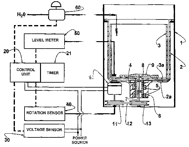
Figure 1 is block diagram of the system of the present
invention associated with an automatic laundry
machine;
Figure 2 is a graph with the curves showing the
variation of rotation of the electric motor for
obtaining the reference and operation times during
acceleration and deceleration.
Detailed Description of the Invention
As mentioned above and illustrated in figure 1 of the
drawings, the present system for detecting a load of
clothes is applied. to an automatic laundry machine of
the type which comprises a structural casing 1,
generally defined by a prismatic cabinet, within which
is mounted, through suspension means, not illustrated
and. which may present any adequate construction
belonging or not to the state of the art; a tub 2,
generally cylindrical and within which. is coaxially
rotatively mounted a basket 3, generally in the form
of a cylindrical drum, having perforated lateral and
bottom walls and which is superiorly open and
dimensioned to contain a load of clothed to be washed.
In the laundry machines with a vertical shaft, such as
that illustrated, the basket 3 has its bottom wall 3a
centrally affixed to a tubular shaft 4 projecting
vertically downwardly and outwardly from the tub 2, so
as to be supported by bearings 5 mounted on a bearing
support 6 secured to the bottom wall 2a of the tub 2.
This assembly allows the basket 3 to rotate freely
CA 02519067 2005-09-13
WO 2004/081276 PCT/BR2004/000029
9
around its axis, in the interior of the tub 2 and
seated on the tubular axis 4.
To the tubular shaft 4 there is rotatively supported,
generally through bushings 7, a central shaft 8 to
whose upper end is secured an agitator 9 positioned on
the bottom wall 3a of the tub 3.
The lower end of the central shaft 8 projects
outwardly from the tubular shaft 4, in order to
receive a driven pulley 13 which is operatively
coupled, through. a belt 12, to a drive pulley 11
secured to the shaft of an electric motor 10 mounted
to the structural casing 1 of the machine, usually
being directly or indirectly attached to the bottom
wall 2a of the tub 2.
Although. not illustrated in figure l, it should be
understood that the laundry machine generally further
comprises a locking device to lock the tubular shaft 4
in relation to the structural casing 1 during the wash
cycles to be performed by the machine, when only the
agitator 9 is impelled by the electric motor 10 in
opposite directions, to effect the movement of the
load of clothes immersed in the washing liquid inside
the basket 3.
It should be further understood that the automatic
laundry machine might present different constructions,
as long as it is provided with a basket provided in a
tub and which is selectively rotatively driven by an
electric motor.
In order to command automatically the operations of
the machine, there is provided a control unit 20 for
the electronic processing of data and which is
operatively associated with a voltage sensor 30, a
rotation sensor 40, a level meter 50, and an inlet
valve means 60 to control the admission of the washing
liquid, generally water, to the interior of the basket
CA 02519067 2005-09-13
WO 2004/081276 PCT/BR2004/000029
3.
The voltage sensor 30 is usually defined by a
voltmeter mounted in the machine to detect the value
of the voltage supplied to the electric motor 10 an to
5 send to the control unit 20 signals representative of
the detected voltage values. The provision of the
voltage sensor 30 allows the control unit 20 to
consider the voltage value of the power source of the
electric motor 10 in any processing operation to be
10 performed thereby.
The rotation sensor 40 takes the form of a tachometer
that is operatively associated with the electric motor
10 to supply the control unit 20 with. signals to be
converted in data representative of the rotation of
the electric motor 10.
In a particular way of carrying out the invention, a
level sensor 50 is provided, usually in the form of a
pressure switch that sends, to the control unit 20,
signals representative of different, generally three,
levels of the washing liquid to fill the basket 3.
In this construction, whenever the washing liquid
reaches any of the levels predetermined by the washing
program, the level meter 50 sends a respective signal
to the control unit 20, which processes this signal
and sends a signal to the inlet valve means 60,
closing the latter and interrupting the supply of the
washing liquid to the machine.
The inlet valve means 60 can take the form of an
electrovalve, for example, whose energi~ation is
commanded by the control unit 20.
The control unit 20 is constructed to process the
signals received from the different components
operatively associated therewith, in order to produce
a signal representative of the load of clothes
inserted in the basket 3.
CA 02519067 2005-09-13
WO 2004/081276 PCT/BR2004/000029
11
The control unit 20 is supplied, in a presetting phase
of the machine, with data representative of the medium
torque of the electric motor 10 in different voltage
values of the power source, generally in different
voltage ranges of about 5V.
Thus, the control unit 20 is able to process the
voltage signal received from the voltage sensor 30 and
to determine the value of the medium torque of the
electric motor 10 for the detected voltage of the
power source.
According to the invention, in the presetting phase of
the machine, which. generally occurs during
manufacture, the basket 3 is rotatively driven upon
the energization of the electric motor 10, from a rest
condition, accelerating until reaching a predetermined
rotation of the electric motor of about 1.300 rpm, the
latter being de-energized so as to decelerate, jointly
with the basket, to reduced rotation values, including
the rest zero value.
During the acceleration and deceleration of the
basl~et, the control unit 20 detects, by means of the
rotation sensor 40, the lnstallts 1n which the rotation
of the shaft of the electric motor 10 reaches two
distinct and predetermined rotation values, both in
the acceleration and in the deceleration phases of the
basket 3. These distinct and predetermined rotation
values of the electric motor 10 can be, for example of
about 660rpm and 1120rpm, with a difference of about
460rpm between said values.
Besides detecting said rotation values of the electric
motor 10, the control unit 20 receives, through a
timer 21 incorporated thereto, data representative of
the acceleration reference time Ta1 and deceleration
reference time Td1 of the electric motor 10 between
said distinct and predetermined rotation values.
CA 02519067 2005-09-13
WO 2004/081276 PCT/BR2004/000029
12
Once obtained the data representative of the
acceleration and deceleration reference times Tal and
Tdl, with the basket in the unloaded condition and the
electric motor 10 being energized at a determined
voltage, the control unit 20 determines the medium
torque Mmot of the electric motor for that voltage
value and then calculates the moment of inertia Jv in
the unloaded condition of the basket 3, establishing
initially zero value for the resistive torque Mres
(friction torque) of the rotary assembly, using the
following equations:
(1) Tal = 2~ rpm x Jv
60 Mmot - Mres
( 2 ) Td1 = 2~t rpm x Jv
60 Mres
Where:
Mmot = Medium torque of the electric motor
Mres = Resistive torque (friction torque)
Jv - Reference moment of inertia with the basket
unloaded
Jc - Moment of inertia of the basket with. a load of
clothes
Considering the resistive moment Mres as being
initially zero in the equation (1), the control unit
20 processes the already received data, in order to
calculate a first value for the moment of inertia Jv
of the basket 3 in the unloaded condition. With the
initial value of the moment of inertia Jv in the
unloaded condition, the control unit 20 calculates the
resistive moment Mres by means of the formula (2) and
subsequently utilizes said value to recalculate. the
moment of inertia Jv in the unloaded condition by the
formula (1), repeating this procedure until the
difference between the Jv values reach a determined
value close to or equal to zero. The value of the
CA 02519067 2005-09-13
WO 2004/081276 PCT/BR2004/000029
13
moment of inertia Jv in the unloaded condition for
each manufactured machine is then recorded as the set
up of each machine in the respective control unit 20.
Still according to the present system, before each
washing operation of the machine, the control unit 20
records, by means of the voltage sensor 30, the
voltage supplied to the electric motor 10, so as to
select the respective value of the medium torque Mmot,
and energizes the motor, in order to accelerate it
jointly with the basket 3 already containing the load
of clothes to be detected, until the predetermined
maximum rotation has been reached, passing by said
distinct and predetermined rotation values under
acceleration and then, after the de-energization of
the motor, under deceleration, allowing the control
unit 20 to record the data representative of the
acceleration and deceleration times Ta2 and Td2 during
operation with the load of clothes.
With the data representative of the medium torque Mmot
and of the acceleration and deceleration times Ta2 and
Td2 with the load of clothes, the control unit 20
calculates the moment of inertia Jc of the basket 3
containing the load of clothes to be detected, by
using the same procedure described in relation to the
determination of the moment of inertia Jv of the
empty, i.e. unloaded, basket 3.
Once determined the moment of inertia Jc of the basket
3 with the load of clothes, the control unit 20 begins
to calculate the load of clothes by the difference
between the moments of inertia Jc in the loaded
condition and the moment of inertia Jv in the unloaded
condition, producing a respective signal to be used in
a subsequent operation of the machine to be performed
with at least one parameter depending on the value of
the load of clothes placed in the basket 3.
CA 02519067 2005-09-13
WO 2004/081276 PCT/BR2004/000029
14
In a particular form of applying the present system,
the control unit 20 associates the data representative
of the load of clothes with a determined level of the
washing liquid inside the basket 3. When this level,
which is determined as adequate by the control unit
20, is detected by the level meter 50, the control
unit 20 instructs the closing of the inlet valve means
60, interrupting the supply of the washing liquid to
the machine.
The subsequent operations may vary as a function of
the operation programs associated with the control
unit and which are generally selected by the user.