Note : Les descriptions sont présentées dans la langue officielle dans laquelle elles ont été soumises.
CA 02519683 2005-09-15
MOBILITY ASSISTANCE APPARATUS AND METHOD
TECHNICAL FIELD
The present invention is directed to an improved mobility assistance
apparatus and a method of improving the mobility of a person using a walking
aid such as a cane, crutch or walker.
BACKGROUND
For over a century crutches and canes have remained virtually
unchanged. Modifications to the crutch or cane itself have generally focused
on ergonomic improvements in the physical structure versus functionai
improvements to mobility. As such, modern ambulatory aids continue to suffer
from many of the same functional limitations that plagued their predecessors.
An example of an early crutch, in U.S. Pat. No. 127,028 issued May 21,
1872, involves the use of a round rubber tip made of respective layers of
rubber and canvas, each exposed at the tip, to prevent the crutch from
slipping on a wet surface. The use of a passive curved rocker provided at the
lower end of the crutch to increase the progression or ground covered with
use of the crutch is taught by U.S. Pat. No. 267,680 issued Nov. 21, 1882. A
pneumatic cushion is used to form a curved rocker or bearer at the tip of the
crutch in the patent to Mueller, U.S. Pat. No. 1,254,061 issued Jan. 22, 1918.
2o The U.S. Pat. No. 1,277,009 to Weldon, issued Aug. 27, 1918, teaches the
use of curved segmental base pieces at the tip of the crutches for ground
engagement.
More recently, examples of annular crutch tips with features to resist
slipping when engaged with the ground are shown by U.S. Pat. Nos.:
3,040,757; 4,098,283; 4,411,284; 4,237,915 and 4,708,154. A radial crutch tip
assembly with a base bottom surface and a resilient boot having a shape of a
rocker is disclosed by Davis in each of U.S. Pat. Nos. 5,353,825; 5,409,029
and 5,465,745.
In other examples of walking aids, Wilkinson, U.S. Pat. No. 4,899,771,
provides a foot member for the walking aid which is curved upwardly at its
front and back ends to permit limited rolling of the foot member when used
CA 02519683 2005-09-15
2
with a cane or crutch during a walking procedure. Similarly, Stephens
discloses in U.S. Pat. No. 5,331,989 curving the front, rear and inner sides
of
the foot member of a walking aid to permit limited rolling of the crutch tip
laterally as well as forward and backward.
Galan, in U.S. Pat. No. 5,829,463 provides the crutch tip with a heel
portion or extension extending rearwardly from the tip at an upward angle.
The heel portion is used to prevent slipping when the user is rising from a
seated position. Semanchik et al. disclose in U.S. Pat. No. 4,493,334 a
walking aid having a foot pad shaped with a curved sole to simulate an
1o anatomical foot for achieving a rocking movement in use by imitating the
phases of a normal gait, i.e. heel strike, foot flat and toe off. A published
U.S.
patent application, U.S. Ser. No. 2001/0027802 Al to McGrath, is directed to
a walking aid comprising a shaft and a foot assembly, in which the foot
assembly includes in combination a sleeve member and a foot member
adapted for relative axial sliding movement and including resilient movement-
restraint means for alleviating problems from shock loading transferred up the
walking aid to the user's hand, wrist, arm and shoulder.
One of the single largest deficiencies of conventional walking
assistance devices is the excessive amount of energy needed to stabilize the
walking system (the device and the user's body) with the ground, and to
efficiently move the user's body through space. In fact, a crutch user expends
as much as 2.5 times more energy to move his/her body mass, in space, as
compared to an able bodied person. Furthermore, the lack of sufficient
surface area at the ground engaging surface of a walking assistance device
engenders other dangers such slippage on uneven or slick surfaces. While
improvements have been made with respect to the surface area at the point of
contact for walking assistance devices, these improvements have been one-
dimensional due to the limitations of the designs. It has been found by
Applicants that the principal limitation to even the most progressive crutch
or
cane tip, with respect to surface area and/or surface textures, is the
inability of
these devices to stabilize the walking system while simultaneously translating
the vertical forces associated with crutch/cane ambulation into forward
propulsion and mobility. There is a need for an improved mobility assistance
CA 02519683 2009-03-25
3
apparatus capable of stabilizing the walking system while lessening the user's
necessary energy expenditure and discomfort associated therewith.
SUMMARY OF THE INVENTION
An object of the present invention is to address the aforementioned need. To
this end, the present invention is an improved mobility assistance apparatus
and a
method of improving the mobility of a person using a walking aid, which lessen
the
user's necessary energy expenditure and discomfort associated therewith by
translating the vertical forces associated with ambulating using a walking aid
into
forward propulsion and mobility while at the same time stabilizing the walking
system.
Accordingly, in one aspect of the present invention there is provided a method
of improving the mobility of a person using a walking aid, comprising:
providing a
resilient device substantially vertically oriented, the resilient device
including a
resilient foot, ankle and an upstanding, anteriorly facing, convexly curved
shank, said
resilient device being capable of storing and releasing energy in response to
forces
associated with ambulating using a walking aid which provides sagittal and
transverse plane motion to generate forward propulsion to aid mobility; and
connecting the upper end of the device to a lower portion of the walking aid
with the
device extending substantially below the walking aid for ground engagement and
for
generating forward propulsion to aid mobility with ambulating using the
walking aid.
According to another aspect of the present invention there is provided a
mobility assistance apparatus comprising, in combination: a walking aid; and a
resilient substantially vertically oriented device connected to a lower
portion of the
walking aid for ground engagement and for generating forward propulsion to aid
mobility, wherein the resilient device is a foot, ankle and an upstanding,
anteriorly
facing, convexly curved shank, the resilient device having an upper end
connected to
said lower portion and being capable of storing energy during force loading
and
releasing stored energy during force unloading, said device providing sagittal
and
transverse plane motion, wherein said device has a dynamic response
characteristic
to forces associated with ambulating using the walking aid which generates
said
forward propulsion to aid mobility.
The walking aid is preferably selected from the group consisting of a crutch,
a
cane, and a walker. The device connected to a lower port of the
CA 02519683 2005-09-15
4
walking aid, the resilient prosthesis in the example embodiment, is capable of
sagittal and transverse plane motion in response to forces associated with
ambulating using the walking aid. This ensures that the bottom, ground
engaging surface of the device/resilient prosthesis remains parallel to the
ground, maintaining maximum contact and traction throughout the ambulatory
cycle.
These and other objects, features and advantages of the present
invention will be more apparent from a consideration of the following detailed
description of disclosed example embodiments of the invention and the
lo accompanying drawings.
BRIEF DESCRIPTION OF DRAWINGS
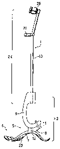
FIG. 1 is a left side view of a mobility assistance apparatus according
to an embodiment of the invention.
FIG. 2 is an enlarged view from below and to one side of a coupling
element of the apparatus of FIG. I by which a foot keel and a shank of the
apparatus are connected.
FIG. 3 is an enlarged left side view of a portion of the apparatus of FIG.
I showing the connection between the lower end of a support member of the
apparatus and the upper end of the shank.
FIG. 4 is a left side view of another form of a resilient lower extremity
prosthesis for use in the apparatus of FIG. 1, the prosthesis having an outer
protective covering, shown in outline, the covering having a slip resistant
lower surface for ground engagement, a male pyramid connector of a
male/female pyramid connection system being shown for connecting the
prosthesis to a lower end of a supporting member of the apparatus.
FIG. 5 is a side view of another embodiment of a prosthetic foot for use
in the mobility assistance apparatus, wherein the calf shank and foot keel and
also a posterior calf device of the prosthesis are monolithically formed, the
distal end of a spring of the posterior calf device being pivotably connected
to
the posterior of the foot keel.
FIG. 6 is a rear view of the prosthesis of FIG. 5.
CA 02519683 2005-09-15
FIG. 7 is a side view of another example of a prosthetic foot similar to
that of FIGS. 5 and 6 for use in the mobility assistance apparatus, but where
the foot keel, calf shank and posterior calf device are monolithically formed
with three, side by side longitudinal sections freely movable with respect to
5 one another at their distal ends but connected at the proximal end of the
calf
shank, with the center section being wider, and at its distal surface higher,
than the outer sections.
FIG. 8 is a top view of the prosthesis of FIG. 7.
FIG. 9 is a front view of the prosthesis of FIGS. 7 and 8.
FIG. 10 is a rear view of the prosthesis of FIGS. 7-9.
FIG. 11 is a side view of another form of the calf shank and foot keel of
a prosthesis for the mobility assistance apparatus of the invention wherein
the
shank is monolithically formed with a posterior portion of the foot keel,
which
is connected by fasteners to a forefoot and midfoot forming member of the
prosthesis.
FIG. 12 is a top view of the calf shank and foot keel of FIG. 11.
FIG. 13 is a rear view of the calf shank and foot keel of FIGS. 11 and
12.
DETAILED DESCRIPTION OF EMBODIMENTS
Referring now to FIGS. 1-3 of the drawings, a mobility assistance
apparatus 1 according to a preferred embodiment is formed of a walking aid 2
in the form of a forearm crutch and a device 3 connected to a lower portion of
the walking aid for ground engagement. The device 3 has a dynamic
response characteristic to forces associated with ambulating using the
walking aid which generates forward propulsion to aid mobility. The device 3
in the embodiment is a resilient lower extremity prosthesis, e.g. a prosthetic
foot, which stores energy during force loading and releases stored energy
during force unloading to generate propulsive force. In the example
embodiment the device 3 is a prosthesis according to commonly owned U.S.
Pat. No. 6,562,075.
CA 02519683 2005-09-15
6
The prosthesis 3 includes a resilient foot 4, ankle 5 and calf shank 6.
The foot 4 includes a foot keel 7 and optionally a protective covering not
shown in FIG. 1 but like covering 8 shown in outline in FIG. 4, for example.
The covering 8, which may be formed of rubber, has ridges 9 on the bottom,
ground engaging surface thereof to resist slipping during use. If a separate
protective covering is not employed on the device 3, ridges or other surface
irregularities can be provided directly on the under surface of the foot keel
to
resist slippage as discussed below.
The shank 6 is connected to the foot keel by way of a coupling element
lo 10 and fasteners 11 and 12 to form the ankle 5 of the prosthesis. At least
a
lower portion of the shank is anterior facing convexly curved. The foot keel
is
upwardly arched in its midportion. The adjacent radii of curvatures of the
resilient foot keel and calf shank of the prosthesis create a dynamic response
capability and motion outcome of the prosthesis in a direction having
horizontal and vertical components as explained with reference to FIGS. 1
and 2 of U.S. Pat. No. 6,562,075, to generate a propulsive force during
ambulating.
The walking aid 2 of the apparatus 1 is formed with a hollow staff 13
that serves as a support member capable of bearing vertical forces from the
weight of the user on the crutch during use as a walking aid. A hand grip 25
and forearm support 26 are mounted on the staff. The length of the staff could
be adjustable as by the use of adjustably telescoped staff portions, not
shown.
While the walking aid 2 in the mobility assistance apparatus 1 is a forearm
crutch, other types of walking aids could be used as the walking aid in the
apparatus, including another type of crutch, a cane, or a walker, for
maximizing functionality and mobility, while lessening the user's necessary
energy expenditure and discomfort associated therewith.
The device 3 is preferably capable of sagittal and transverse plane
motion in response to forces associated with ambulating using the walking
3o aid. Transverse plane motion, provided for example by the provision of
longitudinally extending expansion joints 23 in the foot keel as disclosed in
related U.S. Pat. No. 6,562,075 and/or by the use of a coupling element
permitting motion of the foot about a joint axis which is at least primarily
in the
CA 02519683 2007-05-04
7
frontal and transverse planes as shown in FIGS. 28-35 of commonly owned
related U.S. Patent Application Publication No. 2005/0177250, ensures,
together with sagittal plane motion capability, that the bottom surface of the
foot keel will remain parallel to the ground, maintaining maximum contact and
traction throughout the ambulatory cycle. The energy storing prosthetic foot 3
is capable of enhancing and/or replicating the propulsion that an individual
would experience at the foot, ankle, and calf during the gait cycle, if
uninjured
or able bodied.
In the absence of a protective covering on the prosthesis 3 as shown in
FIG. 4, a rubber surface or a compressible foam surface is preferably bonded
to the underside of the foot keel 7 using an epoxy glue, for example. The
rubber or foam surface is preferably provided with a slip resistant/traction
characteristic. For example, corrugated vanes could be formed on the ground
engaging rubber or foam surface for increased traction over wet surfaces. In
addition, or alternatively, a boot which fits over the entire body of the
prosthetic foot keel, excluding the shank, can be used to achieve variable
traction needs, the bottom surface of the boot being provided with a slip
resistant surface, e.g. cleats, ridges, etc.
The releasable connection between the lower end of staff 13 and the
upper end of shank 6 in the apparatus 1 is shown in the enlarged view of FIG.
3. The upper end of the shank is formed with an elongated opening 14 for
receiving the lower end of staff 13. Once received in the opening, the staff
is
securely clamped to the shank by tightening bolts 15 and 16 to draw the free
side edges 17 and 18 of the shank along the opening together. This
connection can be readily adjusted by loosening the bolts, telescoping the
staff relative to the shank to the desired position and reclamping the staff
in
the adjusted position by tightening the bolts.
The connection between the prosthesis and the walking aid/support
member is not limited to that shown in the example embodiment of FIGS. 1-3.
Other types of connections including a conventional male/female pyramid
system, for example, could be employed. The prosthetic foot 19 in FIG. 4, for
use in a mobility assistance apparatus of the invention, has an adapter 20
bolted to the upper end of the shank 21. The adapter 20 has a male pyramid
CA 02519683 2007-05-04
8
22 thereon for reception in a complementarily shaped socket of an adapter
provided on the lower end of staff 13.
The device 3 according to the invention may be formed from acetal
homopolymer or copolymer (Delrin/Celcon), for example, or other materials
including aluminum, carbon or graphite composites, glass, and/or Kevlar. In
the preferred embodiment the device 3 is formed of acetal plastic, by either
machining or injection molding.
The prosthetic foot 19 in FIG. 4 is similar to that in FIG. 1 although the
shank 21 thereof is reversely curved on itself above an anterior convexly
curved lower portion. Fins 24 are formed on the posterior side of the
reversely
curved portion of the shank to alter the flexing characteristic of the shank
as
discussed with respect to FIGS. 28-32 of commonly owned related U.S.
Patent Application Publication No. 2004/0122529.
The device 3 of the invention is not limited to the two examples of
FIGS. 1 and 4. Other devices, particularly lower extremity
prostheses/prosthetic feet capable of storing and releasing energy during use
to generate propulsion could be used in the mobility assistance apparatus and
method of the invention for stabilizing the walking system and lessening the
user's necessary expenditure of energy and discomfort associated therein.
Examples of additional prosthesis for use in the mobility assistance apparatus
of the invention are shown in FIGS. 5-13. These prostheses are relatively
inexpensive in that they can be monolithically formed as by injection molding
acetal plastic. The resulting mobility assistance apparatus employing the
prosthesis is able to create power for enhancing mobility yet is low cost.
The prosthetic foot 147 of FIGS. 5 and 6 is characterized by a calf
shank 148, foot keel 149 and posterior calf device 150 which are
monolithically formed. The calf shank 148 has an anterior facing convexly
curved lower portion extending upwardly from the foot keel as in previously
described prostheses. The posterior calf device 150 is in the form of an
elongated, resilient, curved spring connected at its proximal end to an upper
portion of the calf shank and at its distal end the spring is pivotably
connected
to a posterior portion of the foot keel by a bracket with pivot pin 151
mounted
CA 02519683 2005-09-15
9
on the distal end of the spring with the pin extending through an aperture 152
in the posterior end of the foot keel. The ends of pins 151 are anchored in
the
openings 152 in the foot keel as shown in the drawings. With anterior or
posterior motion of the upper end of the calf shank in gait with the mobility
assistance apparatus of the invention, the concavity of the curved spring will
be expanded or compressed to store energy within the motion limits of the
spring. The stored energy will then be returned upon force unloading in gait
to
add to the kinetic power available for propulsive force of the user's body.
The prosthesis in FIGS. 7-10 is a prosthetic foot 152 having three
1o longitudinal sections 153-155. Each longitudinal section is monolithically
formed with a foot keel 156, calf shank 157 and posterior calf device 158. The
sections 153-155 are movable independent of one another at their distal ends,
where they are separated by gaps 159, but the sections are integral at their
proximal ends, e.g. at the upper end of the calf shank. This integral
construction can be provided by use of fasteners for connecting the proximal
ends of the respective, separately formed longitudinal sections to one
another. Alternatively, the resilient longitudinal sections can be
monolithically
formed with one another such that they are connected at their upper ends
while freely movable relative to each other at their distal ends where gaps
159
separate the sections.
The center longitudinal section 154 in the prosthesis 152 is wider than
the medial and lateral sections 153 and 155 and also, at its distal end, it is
higher than the sections 153 and 155. This construction provides advantages
in support on uneven or inclined surfaces as discussed previously in
connection with the use of a plurality of longitudinal anterior and posterior
foot
keel struts separated by expansion joints. The number of the plurality of
longitudinal sections employed in the prosthesis can be other than three and
the relative widths of the sections can be varied from that shown in FIGS. 7-
10. The distal ends of the curved spring of posterior calf device 158 of each
longitudinal section is formed integrally with the hindfoot of its foot keel
156
rather than being pivotably connected thereto as in the embodiment of FIGS.
5 and 6. A suitable adapter, not shown, is connected to the upper end of the
calf shank of the prosthesis 152 for connection with the support member,
CA 02519683 2005-09-15
hollow shaft 13, of the walking aid 2 to form a mobility assistance apparatus
of
the invention as described in previous embodiments.
Another form of construction for the prosthetic foot for use with the
invention is illustrated in FIGS. 11-13 wherein the prosthetic foot 160
5 comprises a calf shank 161 monolithically formed with a posterior portion
162
and foot keel 163. The resilient member of the shank and hindfoot is
connected to a resilient member 164 forming forefoot and midfoot portions of
the foot keel by fasteners 165 and 166 as shown in the drawings. A posterior
calf device, not shown in FIGS. 11-13, can be formed as part of the prosthesis
1 o as disclosed above. Likewise, an adapter for connection to a support
member
of a walking aid is to be attached to the upper end of the calf shank 161.
This concludes the description of the example embodiments. Although
the present invention has been described with reference to a number of
illustrative embodiments, it should be understood that numerous other
modifications and embodiments can be devised by those skilled in the art that
will fall within the spirit and scope of the principles of this invention.
More
particularly, reasonable variations and modifications are possible in the
component parts and/or arrangements of the subject combination
arrangement within the scope of the foregoing disclosure, the drawings, and
the appended claims without departing from the spirit of the invention. In
addition to variations and modifications in the component parts and/or
arrangements, alternative uses will also be apparent to those skilled in the
art.