Sélection de la langue

Search

Sommaire du brevet 2519836 

Énoncé de désistement de responsabilité concernant l'information provenant de tiers

Une partie des informations de ce site Web a été fournie par des sources externes. Le gouvernement du Canada n'assume aucune responsabilité concernant la précision, l'actualité ou la fiabilité des informations fournies par les sources externes. Les utilisateurs qui désirent employer cette information devraient consulter directement la source des informations. Le contenu fourni par les sources externes n'est pas assujetti aux exigences sur les langues officielles, la protection des renseignements personnels et l'accessibilité.

Disponibilité de l'Abrégé et des Revendications

L'apparition de différences dans le texte et l'image des Revendications et de l'Abrégé dépend du moment auquel le document est publié. Les textes des Revendications et de l'Abrégé sont affichés :

  • lorsque la demande peut être examinée par le public;
  • lorsque le brevet est émis (délivrance).
(12) Brevet: (11) CA 2519836
(54) Titre français: SOUPAPE DE GAZ A SOLENOIDE DANS UN TUBE
(54) Titre anglais: IN-TUBE SOLENOID GAS VALVE
Statut: Périmé et au-delà du délai pour l’annulation
Données bibliographiques
Abrégés

Abrégé français

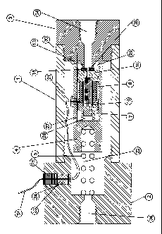
Électrovanne à gaz installée à l'intérieur d'un tube et dotée d'un ensemble solénoïde et de raccords d'entrée et de sortie. La vanne s'ouvre et se ferme en fonction de la différence de pression et à l'aide d'un champ magnétique. Un ressort de compression fixé au corps cylindrique de support est retenu contre le raccord d'extrémité d'entrée tandis qu'un ensemble solénoïde mobile se trouve à l'intérieur du corps cylindrique de support. L'ensemble solénoïde mobile est constitué d'une butée, d'une bride, d'un manchon et d'une bobine électrique, et est retenu par un second ressort de compression fixé à l'intérieur du corps cylindrique de support. Une petite tige magnétique mobile coulisse à l'intérieur du manchon de l'ensemble solénoïde. Un troisième ressort de compression agit sur la tige magnétique afin de fermer hermétiquement la sortie de gaz par l'orifice de prélèvement de la bride de l'ensemble solénoïde.


Abrégé anglais

A solenoid gas valve having a solenoid assembly and inlet and outlet fittings is installed inside a tube. The opening and closing of the valve is operated by the pressure difference with an aid of the magnetic field. A compression spring is attached to the support cylindrical body and held against the inlet end fitting while a moving solenoid assembly is located inside the support cylindrical body. The moving solenoid assembly that consists of a stop, a flange, a sleeve and an electrical coil, is held by a second compression spring that is attached to the inside of the support cylindrical body. A small moving magnetic rod, slides inside the sleeve of the solenoid assembly. Acted by a third compression spring, the magnetic rod seals the gas outlet through the bleed orifice on the flange of the solenoid assembly.

Revendications

Note : Les revendications sont présentées dans la langue officielle dans laquelle elles ont été soumises.


CLAIMS
We claim:
1. An in-tube solenoid gas valve, comprising:
a valve tube, a support cylindrical body, and an axially moveable
solenoid assembly; said valve tube defining a gas inlet passage, a gas
outlet passage and a cavity; an inlet fitting with an axial hole threaded
into said inlet passage for communication with the gas source; an
outlet fitting provides a seal seat and an axial hole threading into said
outlet passage for communication with the outlet; said support
cylindrical body being a cylindrical body defining a chamber, with a
closed end and an open end, fixed within said valve tube; the axis of
said chamber of said support cylindrical body is parallel to the axis of
said axial hole of said outlet fitting;
said axially moveable solenoid assembly comprising a flange, an
electrical coil, a stop, a sleeve and a magnetic rod; said sleeve having
a hollow space and being connected between said stop and said flange;
said flange being a cylindrical disk, providing a small seal seat, a bleed
orifice at one end proximate to said sleeve; an annular plastic insert is
molded onto said flange at the side that is close to the outlet, to
provide seal; an axial hole connecting said bleed orifice providing as a
vent passage to said outlet from said hollow space; said magnetic rod,
able to slide within said hollow space of said sleeve, to open and close
said bleed orifice; said electrical coil being wound around said sleeve
for producing a magnetic field; said axially moveable solenoid
assembly being able to slide in said chamber of said support cylindrical
body between an open and a closed position; said support cylindrical
body, said flange, said stop, and said magnetic rod are ferromagnetic;
said sleeve is non-ferromagnetic; such that, said support cylindrical
-12-

body and said movable solenoid assembly forming a magnetic loop
when said electrical coil is energized; said axially moveable solenoid
assembly further comprising an o-ring located in said flange
circumferentially for segregating said chamber of said support
cylindrical body to a front inside chamber and a back inside chamber;
said front inside chamber proximate to said closed end of said support
cylindrical body and said back inside chamber proximate to said open
end of said support cylindrical body; said o-ring blocking the gas
communication between said front inside chamber and said back inside
chamber; a gas conduit, via a minuscule hole of said support
cylindrical body, for passing the high pressure gas from said cavity of
said valve tube to said front inside chamber of said support cylindrical
body; a second gas conduit, via an eccentric axial small hole of said
stop, for passing gas from said front inside chamber of said support
cylindrical body to said hollow space of said sleeve; a third gas conduit
via said bleed orifice and said axial hole of said flange, for passing gas
from said hollow space of sleeve to the outlet of said axially moveable
solenoid assembly; said minuscule hole having a diameter smaller
than that of both said eccentric axial small hole and said bleed orifice
of said flange of said solenoid assembly; a set of peripheral holes on
said support cylindrical body, proximate said open end of said support
cylindrical body, commuting the high pressure gas in said cavity of
said valve tube and said back inside chamber; when said axially
moveable solenoid assembly is deactivated, said magnetic rod closes
said bleed orifice of said flange and said axially moveable solenoid
assembly moves to said closed position, said annular plastic insert of
said flange pressed on said seal seat of said outlet fitting, stopping the
high pressure gas flow in said cavity through said axial hole of said
outlet fitting.
-13-

2. The in-tube solenoid gas valve as defined in claim 1,
said magnetic rod of said axially moveable solenoid assembly moves to
open said bleed orifice upon activation of solenoid and permitting gas
communication between said hollow space of said sleeve and said axial
hole of said flange; said magnetic rod of said moveable solenoid
assembly moves to close bleed orifice upon deactivation of solenoid,
stopping the communication of gas within said hollow space of said
sleeve and said axial hole of said flange; said axially moveable
solenoid assembly comprising said flange, said electrical coil, said stop,
said sleeve and said magnetic rod is disposed within said chamber of
said support cylindrical body moves to said open position upon the
movement of said magnetic rod.
3. The in-tube solenoid gas valve as defined in claim 1 having a gas
conduit for passing the gas from said front inside chamber of said
support cylindrical body to said hollow space of said solenoid assembly,
via said eccentric axial small hole of said stop.
4. The in-tube solenoid gas valve as defined in claim 2 comprising a
main compression spring for pushing said axially moveable solenoid
assembly towards said seal seat of said outlet fitting to close said
outlet.
5. The in-tube solenoid gas valve as defined in claim 2 further
comprising a compression spring for pushing said magnetic rod
towards said seal seat of said flange to close said bleed orifice.
-14-

6. The in-tube solenoid gas valve as defined in claim 1, said valve
tube is a cylindrical tube, so that said support cylindrical body is
pushed by a compression spring, against said inlet fitting, inserting
into said outlet fitting at said open end; said compression spring is
compressed between said inlet fitting and said closed end of said
support cylindrical body.
7. The in-tube solenoid gas valve as defined in claim 1, said
magnetic rod, able to slide within said hollow space of said sleeve, and
pushed by said biasing element as defined in claim 16 at one end, onto
said small seal seat of said flange to a closed position; a rubber insert
is molded onto said magnetic rod on other end, to provide seal.
8. The in-tube solenoid gas valve as defined in claim 1, when said
magnetic rod moves to open said bleed orifice, the high pressure gas
in said front inside chamber and said hollow space flows into said axial
hole of said outlet fitting; the releasing gas flow rate is faster than the
supplying gas flow rate, it causes a gas pressure differential between
said front inside chamber and back inside chamber, said axially
moveable solenoid assembly moves to said open position, so that, gas
flows between said gas inlet passage and said gas outlet passage;
when said magnetic rod moves to close said bleed orifice, the high
pressure gas flows into said front inside chamber and said hollow
space; gas pressure in said front inside chamber and back inside
chamber reaches an equilibrium, said axially moveable solenoid
assembly moves to said closed position by said biasing element,
stopping gas flows between said gas inlet passage and said gas outlet
passage.
-15-

9. The in-tube solenoid gas valve as defined in claim 1, extend lead
wires of said electrical coil pass through the hole of an internal pass-
through plug which is inserted into said support cylindrical body, to
said cavity of said valve tube.
10. The in-tube solenoid gas valve as defined in claim 9, extend lead
wires of said electrical coil, are soldered on terminals of an external
pass-through connector at one end; external wires which is from a
power supply, through a threaded metal plug with a center hole, is
soldered on terminals of said external pass-through connector at the
other end; electrical current pass through said external wires from said
power supply, said external pass-through connector, to said lead wires
of said electrical coil, to create magnetic field for axial movements of
said magnetic rod.
11. The in-tube solenoid gas valve, defined in claim 10, said external
pass-through connector comprising an o-ring for sealing internal
pressure gas in said cavity of said valve tube; said thread metal plug
thread into said inlet fitting, to hold said external pass-through
connector in said inlet fitting.
-16-

Description

Note : Les descriptions sont présentées dans la langue officielle dans laquelle elles ont été soumises.


CA 02519836 2005-10-12
BE IT KNOWN that We, WANG, Wei-Ching, and WANG,
Chia-Ping., have invented certain new and useful improvements in
IN-TUBE SOLENOID GAS VALVE
Of which the following is a complete specification:
- t -

CA 02519836 2008-02-26
IrIUUSlrY if iuu5ule :`vr.u..............ir,r.=
Cenada Ceneda 2008/02/26
II ~I II~III~NN~~p~~IN~IpIIN~llllql~pl~l~ 057 - 08
p ql p
CiPO oPiC E001009800
DESCRIPTION
BACKGROUND OF THE INVENTION
The configuration of piping systems is complex in alternative fuel vehicles.
The fuel, either natural gas or hydrogen, is normally stored in a high
pressure
tank, controlled by solenoid gas valves when it is in operation. Generally,
the
space in a vehicle is limited; hence a small size of valves and piping systems
is
desired. In addition, having an in-line inlet and outlet ports would simplify
the
arrangement of piping systems.
Valves are used to control the flow rate of the fuel under a specified inlet
pressure. Because of the inlet pressure restrictions and temperature
variations,
it is difficult to design an appropriate valve that meets all the requirements
for the
piping systems. Solenoids of a reasonable size can typically produce a pulling
force that is approximately only 1/100 of the force necessary to unseat a
valve
that is being forced shut by the high-pressure gases. To overcome this, most
of
the gas valves adopt a two-stage process in which a small "bleed" orifice is
first
opened, allowing the high-pressure gas from the storage tank to flow into a
downstream outlet passage way through the "bleed" orifice that leads to the
engine. As the downstream outlet passage way filled with gas, the pressure
will
increase, subsequently reducing the force necessary gradually to unseat the
closed valve. Eventually, the differential pressure between the upstream and
downstream passage ways becomes infinite small to allow the valve to be
-2-

CA 02519836 2008-02-26
opened by a relatively weak pull of the solenoid valve, thus resulting in the
flow of
high-pressure gas from the storage tank to the vehicle engine.
In a typical two-stage valve assembly, two pistons were required in the
operation solenoid assembly, namely primary piston and main piston. The
primary piston is located on top of the main piston. When in operation, the
primary piston is first opened to allow gas flow through a small bleed orifice
located on the main piston to create a pressure difference between the front
and
back sides of the main piston. This difference in pressure causes the valve to
open to gain full gas flow. Since the movement of both pistons affects one
another, the opening stroke (distance) of the primary piston must be equal to
or
larger than that of the main piston to give required operations. Since an
electrical
coil is utilized to generate magnetic field to cause the primary piston to
open, the
longer the primary piston has to travel, the less magnetic force the piston
experiences. This becomes problematic if the pressure of the iniet is
increased.
Hence, to increase the magnetic attraction force that the primary piston
experiences, the magnetic field strength has to be increased. To increase the
magnetic strength, the number of turns of the electrical coil has to be
increased if
the input current stays the same. An increase in number of turns in a coil
also
increases the size of the solenoid assembly, which is undesirable.
In the current design, described hereafter, the equivalent main piston will
move with a solenoid assembly while the movement of equivalent small piston
-3-

CA 02519836 2008-02-26
does not affect the movement of the main piston. It can reasonably reduce the
size of valve and/or increase the gas flow rate.
SUMMARY OF THE INVENTION
The newly designed solenoid valve can be used in a high gas flow and
high pressure application. It is most applicable where a small-sized solenoid
gas
valve with the ability to control high gas flow rate.
It is the object of the present invention to provide an in-tube solenoid gas
valve of the above mentioned general types which avoid the disadvantages of
and improve the performance of the prior art.
It is also the object of the present invention to provide a solenoid gas valve
which has intrinsic ability to reduce the opening stroke (distance) of a
magnetic
rod to either alleviate the electrical power required or to reduce the size of
the
valve. The movement of solenoid assembly is caused by the spring force and
gas pressure; therefore, the opening distance of said solenoid assembly is not
limited by magnitude of magnetic force generated by electrical power via
electrical coil. So that, the present invention can reasonably increase gas
flow
rate.
In keeping with these objects and with others which will became apparent
hereinafter, features of present invention reside, briefly stated in a
solenoid gas
-4-

CA 02519836 2008-02-26
valve which has a valve tube defining a gas inlet passage with an inlet
fitting, a
gas outlet passage with a outlet fitting, and a cavity; a support cylindrical
body,
inserting onto outlet fitting, held by a compression spring against to inlet
fitting. A
solenoid assembly comprising with flange, electrical coil, stop, and sleeve,
movable axially in the chamber of said support cylindrical body, pushed by a
compression spring against on the seat of said outlet fitting to close gas
flow. An
o-ring on said flange of said solenoid assembly segregates the chamber of said
support cylindrical body into front side chamber and back side chamber.
There are two gas conduits to the outlet passage. The main gas flows
through holes on said support cylindrical body peripherally, locating at the
side of
attaching to outlet fitting, into the back side chamber in support cylindrical
body.
Another gas conduit, the gas flow goes through the minuscule hole in said
support cylindrical body, then, via the eccentric axial small hole in the said
stop to
the hollow space of said solenoid assembly.
A magnetic rod, able to slide in said hollow space of said solenoid
assembly, is pushed by a compression spring against on the bleed orifice of
said
flange of said solenoid assembly to close gas flow. A said electrical coil
means
associated with said stop, said sleeve, said flange, and said support
cylindrical
body to provide a magnetic field for movements of said magnetic rod, so that
when said electrical coil is de-energized, said magnetic cylindrical rod
closes said
bleed orifice to seal gas flow and causes a pressure equalization, allowing
said
-5-

CA 02519836 2008-02-26
compression spring to push said solenoid assembly to close the valve. When
said electrical coil is energized said magnetic rod opens said bleed orifice
to let
gas flow to said outlet passage and lowers a pressure which causes a pressure
difference between front and back side of said solenoid assembly, pushing of
said main piston to open the valve.
The lead wires of said electrical coil extend to the external pass-through
connector for powering via the internal chamber in said support cylindrical
body,
internal pass-through plug, inside said cavity of said valve tube.
Hence, in the current design, described hereafter, the stroke of the
movement of magnetic rod is not affected by the required stroke of that of the
solenoid assembly. The stroke of the magnetic rod is minimized and the stroke
of
the solenoid assembly is maximized to result in a reduction of the electrical
coil
size and an increase in maximum flow rate under the same conditions of the
same inlet pressure and the same power supply.
When the solenoid gas valve is designed in accordance with the present
invention, it avoids the disadvantages of the prior art and provide for the
above-
specified advantages.
The novel features which are considered as characteristic for the present
invention are set forth in particular in the appended claims. The invention
itself,
-6-

CA 02519836 2008-02-26
however, both as to its construction and its method of operation, together
with
additional objects and advantages thereof, will be best understood from the
following description of specific embodiments when read in connection with the
accompanying drawings.
BRIEF DESCRIPTION OF THE DRAWINGS
One embodiment of this invention is illustrated in the accompanying drawings,
in
which like numerals denote like parts throughout the several views, and in
which:
Figure 1 is an axial sectional view through a valve constructed in accordance
with this invention, showing the valve in a "closed" state;
Figure 2 is a detailed view of Figure 1 through a valve constructed in
accordance
with this invention, showing the valve in a "closed" state;
Figure 3 is a detailed view, similar to that of Figure 2, showing the small
piston
opens the bleed orifice with an active magnetic field;
Figure 4 is a detailed view, similar to that of Figure 2, showing the main
piston
opens the outlet passage with an active magnetic field. The valve is in a
"fully
open" state;
-7-

CA 02519836 2008-02-26
Figure 5 is a detailed view, similar to that of Figure 2, showing the small
piston
closes the bleed orifice after the magnetic field diminishes.
DESCRIPTION OF PREFERRED EMBODIMENTS
Attention is first directed to Figure 1 and Figure 2, which shows an in-
tube solenoid gas valve in section view. The valve tube 1 has a hollow hole
with
internal threads at both ends, to accept both inlet fitting 2 and outlet
fitting 3. Both
fittings have an axial hole 34 with internal threads for connecting adaptive
fittings
of piping system. A support cylindrical body 4, pushed by a compression spring
5
against said outlet fitting 3, having a chamber 7, provides the space for
movements of the solenoid assembly 6 which comprises of a hollow sleeve 8, a
stop 9, a flange 10 and an electrical coil 11.
A compression spring 12 pushes said solenoid assembly 6 to the seal
seat 13 of said outlet fitting 3 at "closed" state. A plastic insert 14 is
molded onto
said flange 10 to provide seal. A magnetic rod 15 moveable axially in the
hollow
space 16 of said solenoid assembly 6, while a compression spring 17 pushes
said magnetic rod 15 against the small seal seat 18 of said flange 10 at
"closed"
state. A rubber insert 19 is molded onto said magnetic rod 15 to provide seal.
An internal pass-through plug 20, inserting into the support cylindrical
body 4, provides the strain relief of lead wires of coil 21 which extends from
said
-8-

CA 02519836 2008-02-26
electrical coil 11, through said support cylindrical body 4, to the cavity 22
of said
valve tube 1. Said lead wires of coil 21 are soldered onto the terminals of an
external pass-through connector 23 at the bottom of the said connector 23 as
shown in the drawing. The said external pass-through connector 23 is placed in
said inlet fitting 2 with an o-ring 24 that seals high pressure gas. Because
of the
high pressure in said valve tube 1, a metal plug 25 with a center hole is
threaded
into said inlet fitting 2 to hold said external pass-through connector 23.
The high pressure gas passes through said inlet fitting 2 from
upstream piping system to said cavity 22 of said valve tube 1. Gas penetrates
into the front inside chamber 26 of said support cylindrical body 4 through a
miniscule hole 27 and an o-ring 28 divides said chamber 7 of said support
cylindrical body 4 into two chambers, said front inside chamber 26 and said
back
inside chamber 29. Gas from said valve tube 1 flows through holes 30 locating
peripherally into said back inside chamber 29 of said support cylindrical body
4.
The gas in said front inside chamber 26 fills said hollow space16 of said
solenoid
assembly 6 through the eccentric axial small hole 31.
At "closed" state, as shown in Figure 2, both said magnetic rod 15 and
said solenoid assembly 6 are pushed by said compression spring 17 and said
compression spring 12 respectively. Since the seal material is molded onto
both
said magnetic rod 15 and said flange 10, both the spring force and the high
-9-

CA 02519836 2008-02-26
pressure gas push the seal against to said small seal seat 18 and seal seat
13,
therefore blocks the gas to flow to the outlet passage.
Wires from power supply 32, through said thread metal plug 25, are
soldered onto the terminals of said external pass-through connector 23 at the
outer of said valve tube 1, providing the channel for input electrical current
to said
electrical coil 11 which is incorporated with said solenoid assembly 6 to
provide a
magnetic field for movements of said magnetic rod 15 and said solenoid
assembly 6 of the valve. The appropriate materials should be selected for stop
9,
sleeve 8, support cylindrical body 4, and flange 10 so that these components
form a magnetic loop. At the first stage of opening, the solenoid is
energized, as
shown in Figure 3, said magnetic rod 15 is pulled up by the magnetic force to
allow the gas flow in said hollow space 16 flow through bleed orifice 33 and
axial
hole 35 in said flange 10. Because the diameter of said minuscule hole 27 is
smaller than that of said bleed orifice 33, so that, the amount of gas supply
into
said hollow space 16 is less than that of gas released; the pressure
difference
between the front and back side of magnetic rod 15 is equal. The magnetic
force
created by said electrical coil 11 causes said magnetic rod 15 to slide and
remains in "open state".
Since the diameter of said miniscule hole 27 is much smaller than that of
said through hole 30 and said o-ring 28 segregates said chamber 7 into said
front
-10-

CA 02519836 2008-02-26
inside chamber 26 and said back inside chamber 29, the gas pressure in said
front chamber 26 is less than that of said back inside chamber 29, causes a
pressure difference between front and back sides of said solenoid assembly 6.
Said solenoid assembly 6 moves, as shown in Figure 4, allowing flow through
said outlet fitting 3.
When said electrical coil 11 is de-energized, as shown in Figure 5,
said magnetic rod 15 moves against the small seal seat 18 pushed by the
compression spring 17. While high pressure gas enters the hollow space 16
through a minuscule hole 27 and a eccentric axial small hole 31, builds up the
gas pressure in said hollow space 16 of said solenoid assembly 6. The pressure
in said hollow space 16 compresses the rubber insert 19 onto the magnetic rod
15 to close the bleed orifice 33.
The increasing gas pressure in said front inside chamber 26 causes
pressure equalization, results in said compression spring 12 pushes said
solenoid assembly 6 against the seal seat 13. This causes the amount of gas
leak to the outlet passage to be less than that of flows into the chamber 7 of
the
support cylindrical body 4. Because of the difference in projected surface
area
between front and back side of said solenoid assembly 6, the force of the
front
side chamber 26 is larger than that of the back side chamber 29. Hence, the
plastic insert 14 of said flange 10 is compressed onto the seal seat 13 to
cease
the gas flow. This is the "closed" state, as shown in Figure 1.
-11-

Dessin représentatif
Une figure unique qui représente un dessin illustrant l'invention.
États administratifs

2024-08-01 : Dans le cadre de la transition vers les Brevets de nouvelle génération (BNG), la base de données sur les brevets canadiens (BDBC) contient désormais un Historique d'événement plus détaillé, qui reproduit le Journal des événements de notre nouvelle solution interne.

Veuillez noter que les événements débutant par « Inactive : » se réfèrent à des événements qui ne sont plus utilisés dans notre nouvelle solution interne.

Pour une meilleure compréhension de l'état de la demande ou brevet qui figure sur cette page, la rubrique Mise en garde , et les descriptions de Brevet , Historique d'événement , Taxes périodiques et Historique des paiements devraient être consultées.

Historique d'événement

Description Date
Lettre envoyée 2018-07-17
Demande de remboursement reçue 2018-04-24
Inactive : Lettre officielle 2017-11-07
Requête visant le maintien en état reçue 2017-10-31
Inactive : Lettre officielle 2017-10-26
Le délai pour l'annulation est expiré 2017-10-12
Requête visant le maintien en état reçue 2017-10-10
Inactive : Paiement - Taxe insuffisante 2016-10-18
Requête visant le maintien en état reçue 2016-10-14
Lettre envoyée 2016-10-12
Inactive : TME en retard traitée 2016-01-14
Requête visant le maintien en état reçue 2016-01-14
Inactive : Lettre officielle 2015-11-10
Inactive : Paiement - Taxe insuffisante 2015-11-09
Lettre envoyée 2015-10-13
Demande de prorogation de délai pour compléter le paiement de la taxe applicable aux petites entités reçue 2015-09-11
Requête visant une déclaration du statut de petite entité reçue 2015-08-10
Requête visant le maintien en état reçue 2015-07-03
Inactive : TME en retard traitée 2015-07-03
Lettre envoyée 2014-10-14
Requête visant le maintien en état reçue 2013-07-19
Inactive : TME en retard traitée 2012-12-19
Requête visant le maintien en état reçue 2012-12-19
Lettre envoyée 2012-10-12
Inactive : Lettre officielle 2012-07-27
Inactive : TME en retard traitée 2011-10-14
Lettre envoyée 2011-10-12
Accordé par délivrance 2009-03-24
Inactive : Page couverture publiée 2009-03-23
Préoctroi 2009-01-05
Inactive : Taxe finale reçue 2009-01-05
Lettre envoyée 2008-11-20
Taxe finale payée et demande rétablie 2008-11-05
Inactive : Lettre officielle 2008-10-31
Réputée abandonnée - omission de répondre à un avis sur les taxes pour le maintien en état 2008-10-14
Un avis d'acceptation est envoyé 2008-08-15
Lettre envoyée 2008-08-15
Un avis d'acceptation est envoyé 2008-08-15
Inactive : Approuvée aux fins d'acceptation (AFA) 2008-07-10
Modification reçue - modification volontaire 2008-02-26
Lettre envoyée 2008-02-06
Exigences de rétablissement - réputé conforme pour tous les motifs d'abandon 2008-01-09
Réputée abandonnée - omission de répondre à un avis sur les taxes pour le maintien en état 2007-10-12
Inactive : Dem. de l'examinateur par.30(2) Règles 2007-09-05
Lettre envoyée 2007-08-16
Inactive : Correspondance - Poursuite 2007-07-24
Lettre envoyée 2007-07-12
Requête d'examen reçue 2007-06-19
Toutes les exigences pour l'examen - jugée conforme 2007-05-29
Exigences pour une requête d'examen - jugée conforme 2007-05-29
Requête d'examen reçue 2007-05-29
Demande publiée (accessible au public) 2007-04-12
Inactive : Page couverture publiée 2007-04-11
Inactive : CIB attribuée 2006-02-24
Inactive : CIB en 1re position 2006-02-24
Inactive : CIB attribuée 2006-02-24
Inactive : Certificat de dépôt - Sans RE (Anglais) 2005-10-28
Inactive : Lettre officielle 2005-10-28
Demande reçue - nationale ordinaire 2005-10-28
Inactive : Correspondance - Formalités 2005-10-27
Déclaration du statut de petite entité jugée conforme 2005-10-12

Historique d'abandonnement

Date d'abandonnement Raison Date de rétablissement
2008-10-14
2007-10-12

Taxes périodiques

Le dernier paiement a été reçu le 2008-11-05

Avis : Si le paiement en totalité n'a pas été reçu au plus tard à la date indiquée, une taxe supplémentaire peut être imposée, soit une des taxes suivantes :

  • taxe de rétablissement ;
  • taxe pour paiement en souffrance ; ou
  • taxe additionnelle pour le renversement d'une péremption réputée.

Les taxes sur les brevets sont ajustées au 1er janvier de chaque année. Les montants ci-dessus sont les montants actuels s'ils sont reçus au plus tard le 31 décembre de l'année en cours.
Veuillez vous référer à la page web des taxes sur les brevets de l'OPIC pour voir tous les montants actuels des taxes.

Historique des taxes

Type de taxes Anniversaire Échéance Date payée
Taxe pour le dépôt - petite 2005-10-12
Requête d'examen - petite 2007-05-29
Rétablissement 2008-01-09
TM (demande, 2e anniv.) - petite 02 2007-10-12 2008-01-09
TM (demande, 3e anniv.) - petite 03 2008-10-14 2008-10-15
Rétablissement 2008-11-05
TM (demande, 5e anniv.) - petite 05 2010-10-12 2008-11-05
TM (demande, 4e anniv.) - petite 04 2009-10-13 2008-11-05
Taxe finale - petite 2009-01-05
TM (brevet, 6e anniv.) - petite 2011-10-12 2011-10-14
Annulation de la péremption réputée 2015-10-13 2011-10-14
Annulation de la péremption réputée 2015-10-13 2012-12-19
TM (brevet, 7e anniv.) - petite 2012-10-12 2012-12-19
TM (brevet, 8e anniv.) - petite 2013-10-15 2013-07-19
TM (brevet, 10e anniv.) - petite 2015-10-13 2015-07-03
TM (brevet, 9e anniv.) - petite 2014-10-14 2015-07-03
Annulation de la péremption réputée 2015-10-13 2015-07-03
2016-01-14
Titulaires au dossier

Les titulaires actuels et antérieures au dossier sont affichés en ordre alphabétique.

Titulaires actuels au dossier
WANG WEI-CHING
CHIA-PING WANG
Titulaires antérieures au dossier
S.O.
Les propriétaires antérieurs qui ne figurent pas dans la liste des « Propriétaires au dossier » apparaîtront dans d'autres documents au dossier.
Documents

Pour visionner les fichiers sélectionnés, entrer le code reCAPTCHA :


Pour visualiser une image, cliquer sur un lien dans la colonne description du document (Temporairement non-disponible). Pour télécharger l'image (les images), cliquer l'une ou plusieurs cases à cocher dans la première colonne et ensuite cliquer sur le bouton "Télécharger sélection en format PDF (archive Zip)" ou le bouton "Télécharger sélection (en un fichier PDF fusionné)".

Liste des documents de brevet publiés et non publiés sur la BDBC .

Si vous avez des difficultés à accéder au contenu, veuillez communiquer avec le Centre de services à la clientèle au 1-866-997-1936, ou envoyer un courriel au Centre de service à la clientèle de l'OPIC.

({010=Tous les documents, 020=Au moment du dépôt, 030=Au moment de la mise à la disponibilité du public, 040=À la délivrance, 050=Examen, 060=Correspondance reçue, 070=Divers, 080=Correspondance envoyée, 090=Paiement})


Description du
Document 
Date
(aaaa-mm-jj) 
Nombre de pages   Taille de l'image (Ko) 
Description 2005-10-11 12 347
Abrégé 2005-10-11 1 21
Revendications 2005-10-11 4 108
Dessins 2005-10-11 5 217
Dessin représentatif 2006-06-07 1 35
Revendications 2008-02-25 5 193
Dessins 2008-02-25 5 187
Abrégé 2008-02-25 1 20
Description 2008-02-25 11 342
Dessin représentatif 2009-03-04 1 23
Certificat de dépôt (anglais) 2005-10-27 1 158
Accusé de réception de la requête d'examen 2007-07-11 1 177
Avis de rappel: Taxes de maintien 2007-07-15 1 121
Avis de retablissement 2008-02-05 1 167
Courtoisie - Lettre d'abandon (taxe de maintien en état) 2007-12-09 1 175
Avis de rappel: Taxes de maintien 2008-07-14 1 122
Avis du commissaire - Demande jugée acceptable 2008-08-14 1 164
Courtoisie - Lettre d'abandon (taxe de maintien en état) 2008-10-30 1 175
Avis de retablissement 2008-11-19 1 165
Avis de rappel: Taxes de maintien 2011-07-12 1 121
Avis concernant la taxe de maintien 2011-10-24 1 171
Quittance d'un paiement en retard 2011-10-24 1 164
Avis de rappel: Taxes de maintien 2012-07-15 1 128
Avis concernant la taxe de maintien 2012-11-22 1 171
Quittance d'un paiement en retard 2012-12-27 1 163
Avis de rappel: Taxes de maintien 2013-07-14 1 120
Avis de rappel: Taxes de maintien 2014-07-14 1 120
Avis concernant la taxe de maintien 2014-11-24 1 170
Deuxième avis de rappel: taxes de maintien 2015-04-13 1 117
Avis de rappel: Taxes de maintien 2015-07-13 1 127
Quittance d'un paiement en retard 2015-07-15 1 163
Avis de paiement insuffisant pour taxe (anglais) 2015-11-08 1 91
Avis concernant la taxe de maintien 2016-01-11 1 171
Quittance d'un paiement en retard 2016-01-26 1 163
Avis de rappel: Taxes de maintien 2016-07-12 1 121
Avis de paiement insuffisant pour taxe (anglais) 2016-10-17 1 92
Avis concernant la taxe de maintien 2016-10-17 1 178
Deuxième avis de rappel: taxes de maintien 2017-04-12 1 130
Avis de rappel: Taxes de maintien 2017-07-12 1 119
Correspondance 2005-10-27 1 33
Correspondance 2005-10-26 1 27
Correspondance 2005-10-27 9 295
Correspondance 2007-07-15 1 52
Correspondance 2007-07-11 1 83
Correspondance 2007-07-11 1 84
Correspondance 2007-08-15 1 9
Correspondance 2007-12-09 1 90
Correspondance 2008-02-05 1 65
Taxes 2008-01-08 1 54
Correspondance 2008-07-14 1 53
Correspondance 2008-08-14 1 82
Correspondance 2008-10-30 1 20
Correspondance 2008-10-30 1 92
Correspondance 2009-01-04 1 28
Taxes 2008-10-14 1 28
Taxes 2008-11-04 1 46
Correspondance 2011-07-12 1 62
Correspondance 2011-10-24 1 67
Correspondance 2011-10-24 1 87
Taxes 2011-10-13 1 61
Correspondance 2012-07-15 1 62
Correspondance 2012-07-26 1 18
Taxes 2012-12-18 1 134
Taxes 2013-07-18 1 130
Paiement de taxe périodique 2015-07-02 1 58
Correspondance 2015-08-09 2 60
Correspondance 2015-09-10 1 19
Courtoisie - Lettre du bureau 2015-11-09 2 53
Paiement de taxe périodique 2016-01-13 1 138
Paiement de taxe périodique 2016-10-13 1 115
Paiement de taxe périodique 2017-10-09 1 161
Courtoisie - Lettre du bureau 2017-10-25 1 30
Paiement de taxe périodique 2017-10-30 2 61
Courtoisie - Lettre du bureau 2017-11-06 1 30
Remboursement 2018-04-23 2 38
Courtoisie - Accusé de réception de remboursement 2018-07-16 1 22