Note : Les descriptions sont présentées dans la langue officielle dans laquelle elles ont été soumises.
CA 02519968 2005-09-16
1
ELECTRIC CENER~1.TQR FOR VEHICLE
PRODUCING DUAL OUTPUT VC?L'I'~1,GES
CROS3..REFERENCE TO RELATED APPLICATION
This application claims prioxity from Japanese Patent
Application No. 2004 - 270 13, f led on September 17, 2004, the
content of which is hereby incorporated by reference into this
application.
F3.l~.Ck~C'xROUND OF THE INVENTION
1. Technical Field of the Invention
The present invention relates generally to electric
generators and chagrining systems fox vehicles. l~oxe paxticulaxly,
the invention relates to an electx-i.c generator for a vehicle, which
i5 produces two different output voltages at the same tune.
2 Description of the Related Art
Tn recent automobiles, the use of electric Ioads that require
large electric power, such s.s an electric power steering apparatus
and an electric compressor, has increased. This results in
introduction of high voltage (for example, 42V) power systems,
which can largely contribute to miniaturization and efficiencies of
power generation and supply apparatuses or devices on the
vehicle.
On the other hand, filament Ioads, such as a headlamp,
2~ and DC apparatuses or devices that use a commutator, such as a
wiper and a starter, axe not suitable for use with a hzgh voltage
CA 02519968 2005-09-16
2
powex system, in view of life time anal increase of spars in
operation. Thus, low voltage (for example, 24~V') power systems are
still necessary for those filamEnt loads aad DC apparatuses or
devices.
'1'o meet both the high and lover voltage requixements, a
vehicle that includes an electric generator producing only a high
output voltage may include a DC-DC ca~xve:rter to produce a low
output voltage; otherwise, it may include an additional electric
generator that, produces a Iow output voltagE.
However, the use of such. additional devious as the DC-DC
converter and the electric generator of low output voltage will
incxease xx~,anufacturing cast and require additional installment
space on the vehxGle.
To solve such a problem, an approacxx is disclosed, for
16 example, in Japanese Patent First Publication loo. T~Q~ - 105512
and Japanese Patent No. X946592. According to the approach, a
single electric generatax is allowed to include a plurality of stator
windings so as to produce both a hitgh and a low output voltage.
However, if an electric generator is designed to include two
sets of stator winding and rectifier, one for producing a high output
voltage and the other for producing a law output voltage, either one
of the t~ocro sets will not be fully utilized when electric loads
operating at the voltage produced thereby are decreased.
Cansequently, the cost/performance ratio of the electric generator
will be high.
x'urther, an another approach may also be considered,
CA 02519968 2005-09-16
3
according to which two circuits for producing respective output
voltages are connected in series, so that a high output voltage,
which is the vector sum of tha output voltages of the two circuits,
can be obtained.
However, .in the above case, since the number of rectifier
elements in the tvcro circuits is large, the forward direction voltage
drops due to recti~ez- elements and the intez-z~.al, iu~capeda,xxce of the
whole circuit will accordingly be large, so that it is diff'xcult to
provide a large power. ~.rther, it is also diff cult to suitably control
x0 the high and low output voltages of the whole circuit, so that both
the output voltages cannot be reliably produced.
SbIIVIMARY O>~' 'I~HE 1NVENT1~11T
The present invention has been made in view of the
above-mentioned problem.
It is, therefore, a primary object of the present invention to
provide an electz'uc generator for a vehicle, which has a simple
structure arid can reliably produce two different output voltages at
the same time.
According to the first aspect of the invention, an electric
generator is provided which includes a rotor, a stator, a rectxf'xex-,
az~,d a regulator.
The rotor incl~.tdes a field winding. The stator ix~.cludes a
fxrst and a second three-phase winding, each of which has three
output terminals coz-responding to respective phases. The xectz~xer
works to rectify outputs of the first and second three~phase
CA 02519968 2005-09-16
wiradings. Th.e regulator works to regulate the outputs o1' tlxe first
and second three-phase windings through controlling a field
current supply to the field winding.
In the above electric generator, the rectifier includes:
b three rectifier element groups each of which includes a first,
a secoxa.d, arzd a third r~:ct'~.f'xex elezx~erat that are connected in
series,
the three rectifier element groups being connected in parallel so as
to hare a fxr$t can~mon connection connecting free terminals of the
'three first rectifying elements and a second common cax~.xxectiox~.
X0 connecting free terminals of the three third rectifyirig elements, all
the rectifier elements of the three groups haviztg the same forward
diurection frox~a the second common cazxnectxon to the first common
connection; and
three fourth rectifier elexnexzts, each of which has one
X5 terminal connected to a connection between the secoxxd azxd third
rectifying elEments of a corresponding one of the three ~rectiifzex
element groups and the other terminal connected to a third
coxxa,xnox~ connection, so as to have a fozyvaxd direction from the
co~.nection to the third common connection.
20 further, in the above electric generator,
each of the three output terminals of the first three-phase
winding is coz~xxacted to a connection between the fixst and second
rectifying elements of a corresponding one of the three rectifier
element groups;
25 each of the three output terminals of the second
three-phase wiz~ding is connected to a connection betweEn the
CA 02519968 2005-09-16
second and third rectifying elements of a cox'~'esporrding one of the
three rectifier element groups; and
the first common connection serves as a high voltage output
terminal to output a first voltage, and the third eazmnon
connection serves as a low voltage output terna.ina~. to output a
second voltage that is lower than the first voltage.
'ffith the above arrangement, it is possible for the electric
ger~erator to produce two dii'ferent output voltages at th.c same fiixn,e
employing a sixxgle rectifier.
Cozx~.pared to an e~cisGizxg electric generator that includes
two serially connected sets of three-phase winding and recter,
the electric generator according to the invention has a much
simpler structure, thus xeduczx~g tl~e fox ward direction voltage
drops due to diodes arid the internal ixxrpedance of the electric
generator.
According to the second aspect of the invention, in the
above electric generator, the regulator controls the field current
supply to the field winding so as to keep a voltage, which is a
fur~tctiorl of one of the first voltage and the second voltage, vvithyxx a.
predetE~~~ed range.
Since the high and low voltage output terminals are linked
with each other in the rectifier, the first and second voltages are
tied to each other during power generation. Accordingly, it is
possible to reliably produce both the first and second voltages
26 through controlling the filed current supply to the field winding
based on ane of the two voltages.
CA 02519968 2005-09-16
G
According to the third aspect of the invention, in the above
electric generator, the stator further includes a core having a first
group of slots, in which the first three-phase vrinding is
accomxnodated, and a second group of slots in which the second
s three-phase wi.ndi,ng is aecomxnodated. ~rther, a ratio of the
number of slots in the fret group to that zr~ the second group is
equal to a ratio of the xa.uxx~.ber of turns ire. the first three-phase
wind~ixxg to that in the second three-phase winding.
With suclx an arrangeiinent, it becomes possible to use a
x0 low-ixxxpedance bar conductor having rectangular cross section,
the use of which generally requires a small number of windings in a.
slot, to form the two three-phase windings. Co~xsequezxtly, the two
thrree-phase wy.;c,dixxgs will lxave lover impedance, thus improving the
efficiency of the electric generator, k~.a,rther, it also becomes
x5 possible to improve the space factor of the two three-phase
windings without sacrificing insulation properties thereof:
According to the fourth aspect of the invention, in the above
electric generator, the field winding may be connected to the low
voltage output terminal.
20 As a result, the second voltage (i.e., the lower voltage) is
applied to the field winding, thus suppressing corrosion of the field
winding and other related components such as slip rings.
Otherwise, the rectifier rnay further include three fifth
rectif er elements, each of which has one terminal connected to a
25 connection between the first and second rectifier elements of a
corresponding one of the three rectifier element groups and the
CA 02519968 2005-09-16
7
other terminal connected to a fourth eoxnmoxl connection, so as to
have a forward direction from the connection to the fourth common
connection, and the filed winding may be connected to the fourth
Gom~o~ CQ~x7lG'C'h.~Ox'7l.
As a result, the first voltage (i.e., the higher voltage) is
applied to the field ~cxrinding, so that the ratio of fihe fZeld current to
the total output current will be small, thus improving the efficiency
of the electric generator. .
According to the fifth aspect of thte invention, the above
electric generator further includes a switch thafi is connected in
series with one of the first and second three-phase windira.gs, and
the regulator turns the switch on when the electric gexaeratox
rotates at a iow speed and off when the electric generator rotates at
a, high speed.
1B As a result, through controlling on/off operation of the
switch; it is possible to reduce the number of turns of effective
winding in stages as the rotational speed of the electric generator
increases, thus increasing the output of the electxi.c get'~,exator.
Moreover, it is also possible to reduce the internal impedance of the
electric generator, thus suppxessixxg decrease in the first voltage
when a large load is connected to the high voltage output terminal.
Fuxtherxx~ore, it is also possible to prevent drop in the second
voltage, thus ensuring stability of the power generation.
According to the 5si~th aspect of the invention, in the above
electric generator, a ratio of the number of . turns in the second
three-phase wxr~d~g to that ix~ the first three-phase wimdi~.g is so
CA 02519968 2005-09-16
8
set to be greater than V2 / (V ~ - V2), where V 1. and V2 are rated
values of the first and second voltages, respectively.
As a result, it is possible to approximate the ratio of the
second voltage to the fxxst voltage to V2 / V 1 txrhen a large electric
load is connected to the low voltage output terminal.
BRIEF DESCI~I~'101~ OF TT~E DRAWIIVCrS
The pxesezxfi ix~vex~~.on will be understood more fully from
the detauled desc~ripdaxx given hereinafter and from the
i0 accompanying drawixa.gs of the preferred embodiments of the
invention, which, however, should not be taken to limit the
ixxvexxtion to the specific embodiments but are far the purpose of
explanation axed understandirxg only.
In the accompanying drawings: '
is FIG. 1 is a schematic view showing the overall configuration
of an eleetriG generator according to the first embodiment of the
inventxor~;
FIG. 2 is a view Showing part of a rotor and a stator of the
electric generator of FICr. Z along the circurnfexexxtial direction;
20 FIG. 3 is a schematic view showing the overall coafiguratzox~
of an electric generator according to the second embodiment of the
invention;
FIG. 4 is a schematic view showing the overall configuration
of an electric generator according to the third embodiment of the
25 i.xxvention; and
FIG. 5 is a graphical ~represenfiation shouring the
CA 02519968 2005-09-16
relationship between the x-atatioxxal speed and output current of
the electric gen,erato~r o~ FIG. 4 in connection with on/off operafiion
of switch groups S l and S2 in the electric generator.
DESCRIPTION OF THE fR.EFE1212E17 E1VI~ODZIU,fENTS
The preferred embadimexxts of the present invention will be
described hereinafter with reference to FIGS. 1 .. 5.
It should be noted that, for the sakE of clarity axed
understanding, identical components having identical functions in
different embodiments of the invention have been marked, where
pvsszble, watla. the same reference numerals in each of the figures.
(First Embodiment
FIG. 1 shows the overall configuration of an electric
generator (or alternator) 100 according to the first embodiment of
the invention. The electric generator 1.00 is for use in an
automobile.
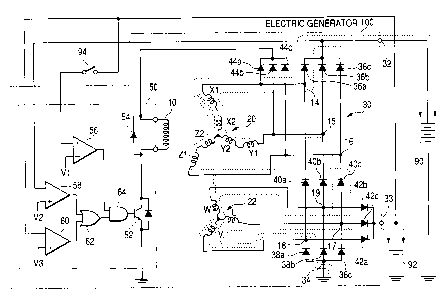
As shot~rx~ in FIG. 1, the electric generator 100 includes a
field wix~dxng 10, a first three-phase winding 20, a second
three-phase W nding 22, a rectifier 30, and a voltage regulator 50.
The field winding 10 is provided in a rotor 7, of the electric
generator 100.
The first and second three-phase windings 20 and 22 are
provided in a stator ~ of the electric generator 100. The ratio of the
number of twrn,s iz~. the first three-phase winding 20 to that in the
second three-phase winding 22 is 2 : 1.
The rectifier 30 includes a plurality of diodes, which serve
CA 02519968 2005-09-16
iv
as rectifier elemez~ta, and is configured to fixll-wave rectify outputs
of the first and second three~phase windings ~0 and 22.
The voltage regulator SO works to regulate output voltages
of the electric geriez'ato~r 100 through controlling a field current
supply to the filed winding 10.
The electric generator 100 fuxfiher xz~cludes a high voltage
output texnrnzz~.al 32 far outputting a high voltage of 42V and a low
voltage output terminal 33 fox outputting a low voltage of 14V. The
high voltage output terminal 32 is connected with a high voltage
battery 90 having a rated voltage of 42V, while the low voltage
output terminal 33 is connected with a low voltage battery 92
hav:irrg a rated voltage of 14V.
FIG. 2 shows part of the rotor 1 and stator 2 of the electric
generator 100 aloxa.g the circumferential direction.
7.5 The rotor 1 is a Lundell claw pole rotox with twelve poles I2.
The field winding 10 is faxx~a,ed ira the innex periphery of the rotor 1
arid the number of turns of the field winding 10 is, for example,
500.
The stator 3 includes a core ~6 that surrounds the rotor 1.
The core 26 is formed by lasxdx7.atix~g tl~ix~. electromagnetic steel
sheets lxaving a prescribed thickness, fox example, of 0.35 mm and
includes 108 slots 24 foamed therein. Within each of the slots 24,
two cor~ductive wires 28 are wound and serially coxinected with
each other.
Further, as shown in FICx. 2, fox each of the poles 12, there
are nixxe corresponding slots 24. The conductive wires 28 in the
CA 02519968 2005-09-16
xz
nine slots 24 zx~,alce up windings Xl., X2, -'V', -Z1, -Z2, U, Y1, Y2, -W,
respectively. Moreover, the windings Xl. and X2 are serially
Goxxnected with each othex to form part of a X-phase winding of tk~.e
first three-phase wixxding 20; the windixxgs -Z1 and -Z2 are serially
connected with each other to form part of a Z-phase winding of the
first three-phase winding 20; and tk~e windings Y 1 and Y2 axe
connected with each other to form a Y-phase winding of the first
three-.phase wir~dixxg 20. 4n the other hand, the windings .-W, -'V", U
make up a W~phase, a V-phase, and a U-phase winding oi' the
to second three-phase winding 22, respectively. It should be noted
that the 3r~inus sign here denotes reversed wiut~dixZg direction and
thus xeversed phase in voltage.
Consequexxt~r, the phase of voltage induced in the X-phase
winding of the first three-phase winding 2~ will be almost reverse
to that of voltage induced in the 'V..phase winding of tk~e Second
three-phase winding 22; the phase of voltage induced in the
Y-phase winding of the first three-phase wiin.dzxa.,g 20~ will be almost
reverse to that of voltage induced in the W-phase winding of the
second three-phase winding 22; and the phase of voltage induced
i.r~ the Z-phase wxx~dimg of the first three-phase winding 20 will be
almost reverse to that of voltage induced in the ~-phase windzng of
the second three-phase wixxd~g 22.
~xxting bacl~ to P'IG. 1, the X, Y, and Z phase windings of
the first three-phase winding 20 have respective output texminals
14, 15, arid 1.6, which are connectEd to the rectifer 34. $~ly,
the U, V, and 'Vii' phase windings of the seoond three-phase winding
CA 02519968 2005-09-16
12
22 have respective output terminals 17, 18, and 19, which are
connected to the rectifier 30.
The rectifier 30 has a three-layer structure. rt includes
three diode groups, each of which includes a posi#ve texvr~,x~al.
diode, a buffer diode, arid a negative terminal diode that are
connected x~, series.
Specifically, the first group includes a positive terstxinal
diode 36a, a buffer diode 40a, and a negative terminal diode 38a;
the second group includes a positive terminal diode 36b, a buffer
IO diode 40b, and a negative terminal diode 38b; and the third group
includes a positive terminal diode 36e, a buffer diode 40c, azxd a
negative terminal diode 3$c.
Further, the three diode gxaups are co~xnected in parallel to
have a fiurst coxxxzxa,orx connection connecting the anodes of the three
positive fiez urinal diodes 36a -- 36c and a second common
connection connecting the cathodes of the three negative terminal
diodes 38a - 38c. As a result, all the diodes in the three diode
groups have the same forward direction from the 'second common
connection to the first commorx cor~trxect:iox~. The first common
connection is connected to a high voltage output tErminal 32 of the
rectifier 3a, while the second common connection is connected to a
negative terminal 34 of the same. The high voltage output terminal
32 is further connected to the positive terminal of the high voltage
battery 90.
Moreover, the output termitxxals 14, 15, and 16 of the X, Y,
and Z phase windings of the first three-phase winding 20 are
CA 02519968 2005-09-16
I3
respectively connected betweezx the diodes 36a and 40a, between
the diodes 36b and 40b, and between the diodes 36c and 40c. Qx~,
the other hand, the output terminals 17, x 8, and 19 of the U, Zl,
~az~d W phase windings of the second three-phase winding 22 are
respectively connected betweexx the diodes 38c and 40c, between
the diodes 38a and 40a, and betweexx the diodes 38b and 40b.
The rectifier 30 further includes three diodes 42a - 42c, the
cathodes of which are respectively connected befiween the diodes
38a arid 40a, between the diodes 3$b and 40b, at~,d between the
diodes 38c and 40c. pza, the other hand, the anodes of the three
diodes 42a -- 42c are connected to a third coxt~oxx comuecfiorr that
is connected to a low voltage output texz~al 33 of the rectifier 30.
'r'he Iow voltage output terminal 33 is further connected to the
positive terminal of the low voltage battery 92.
x5 The xectifxer 30 further includes three diodes 44a - 44c, the
cathodes of which are respectively connected between the diodes
352 axxd 40a, betv~reexx the diodes 36b and 40b, arid between the
diodes 36c and 40c. Oxx the other hand, the anodes . of the three
diodes 44a - 44c are connected to a fourth common connection
that is connected to the voltage regulator 50.
The volt$ge regulator 50 includes' a switch 52, a
freewheeling diode 54, three voltage comparators 56, 58, and 60,
an OR circuit 62, and an AND circuit 64.
The switch 52 is connected in series with the Bled winding
2s 1 o and configured to be selectively turned on and off so as to
control the field current supply from the rectifier 30 to the filed
CA 02519968 2005-09-16
14
winding 10.
The freewheeling diode 54 is connected in parallel with the
field winding J.O, so as to recover the i~xeld current flowing in the
f eld winding I 0 when the switch 52 is turned from on to off.
The voltage comparator 55 has a plus i~.put terminal, to
which the terminal voltage of the low voltage battery' 92 is applied
via an ignition switch 94, ax~.d a z~inus input terminal to which a
reference voltage V 1. is applied. The reference voltage V 1 is so set to
be lower than the term~a.1 voltage o:f the low voltage battezy 92, so
Xfl that when the ignition switch 94 is turned an, a high level signal is
outputted from the voltage comparator 56 to a first input terminal
of the AND circuit 64.
The voltage coxx~.parator 58 has a minus input terminal, to
which the terxninal voltage of the high voltage battery 90 is applied,
and a plus input terminal to which a reference voltage V2 is applied.
The voltage cozxxparator 58 outputs a high level signal to a first
input terxturlal of the OR circuit 52 when the terminal voltage of the
high voltage battery 90 is lower fihan the reference voltage 'tl'2. rt
should be noted that instead of the ter~anuinal voltage of the high
2U voltage battery 90, the output voltage of the high, voltage output
terminal 32 of the rectifier 32 or a voltage that is a function of the
output voltage of the teral 32 may also be applied.
' he voltage comparator 60 has a mi~xus iza.put terminal, to
which the terminal voltage of the low voltage battery 92 is applied,
and a plus input terminal to which a reference voltage V3 is applied.
The voltage comparator 60 outputs a high level signal to a second
CA 02519968 2005-09-16
is
input tern~uinal of the OR circuit 62 when the terminal voltage of the
low voltage battery 92 is lower than the reference voltage V3. it
should be noted that instead of the terminal voltage of the low
voltage battery 92, the output voltage of the Iow voltage output
terminal 33 of the rectifier 30 or a voltage that is a function .of the
output voltage of the terminal 33 zxxay also be applied. .
The 012 circuit 62 has the first grad second input tErminals,
via which sigr~als outputted .from the voltage comparators 58 and
50 are respectively inputted, and outputs a high level sigxxal to a
second input terminal of the AIrTD circuit ~4 when at least one of
the levels of the inputted signals is high. Consequently, when the
termix~al voltage of the high voltage battery 90 becomes lower than
the rEference voltage V2 or/and that of the Iow voltage battery 92
becomes lowex thaxx the referexxce voltage V3 sa that at least one of
a5 the voltage comparators 58 and 60 outputs the high level signal,
the OR circuit b2 outputs the high Ievel signal to the AND circuit
64. .
The AND circuit 54 has the ~'xrst anal secamd :ix~.put terxxals,
via which signals outputted from the voltage caxxxpa;ratar 5~ and
OR circuit 62 are inputted, and outputs a high level signal to the
switch 52 when both the levels of the inputted signals are high.
Since the cornparator 56 continues to output the high level signal
after the ignition switch 94 is turned ox~, the A,ND circuit 64 will
output the high level signal to the switch 52 when the terminal
voltage of the hitgh voltage battery 90 becomes lower than the
reference voltage V2 or/an,d that of the law voltage battery 92
CA 02519968 2005-09-16
is
becomes lower ~az~ the xefexex~ce voltage V3.
Upon receiving the high level signal from the AND circuit b4,
the switch 52 is turned on, so that the filed current is supplied
from the ~rectxfie~r 30 to the bled vc~nding'10.
Having described the overall configuration of the electric
generator 100, operation thereof will be described hereinafter,
First, the startirxg opexatiox~ of the electric generator I00 is
as follows.
When the ignition switch 94 is turned on, the eloctric
generator 100 is driven by' the engine (not shaven) of the vehicle to
rotate. At the same time, the voltage regulator 50 is supplied with
electzxc pawex by a power supply circuit (not shown) so as to be
able to operate.
Then, if the terminal voltage of the high voltage battery 90 is
is lower than the reference voltage V2 arJand that of the low voltage
batfiery 9~ is lower than the reference voltage V3, the switch 52 is
turned on, so thafi the faeld winding 10 is supplied with the field
current. Consequently, a rotating filed is created for the stator 2.
Deferring again to FIGr, 2, far each of the poles ~2, there axe
nine corresponding slots 24 farmed i,xa the caxe 26; thus, the
difference in phase betvcreen voltages induced irx windings in
adjacent slots 24 is equal to ~ /9.
Accordingly, the difference in phase between the voltage
induced in the first three-phase wir~ding 20 and that induced in the
second three-phase winding 22 is equal to Tc /~. For e~cample, the
~-phase winding of the first three-phase winding 20 is formed by
CA 02519968 2005-09-16
17
serially connecting the windings X1 and ~2. Thus, the difference in
phase befiween the voltage induced in the ~~-phase winding and
that induced in the V'-phase winding of the second three-winding
22 is equal to (3/2 x ~ /9), i.e. n /6.
Moreover, since the rafiio of the number of turns ixa, the first
three-phase wirxdiz~g 20 to that in the second three-phase winding
22 ins equal to 2 : I, the ratio of the voltage induced in the first
three-phase winding 20 to that induced xx~. the second throe-phase
windir~g 22 is accordingly equal to 2 : ~.
to Further, as shown in FrG. 1, the voltage induced in the first
three-phase windxxxg 20 is added, via the buffer ditodes 40a -- 40c in
the rectifier ~0, to the voltage induced in the second three-phase
wix~.ding 22. Cormeduently, an electric current path as indicated
with dashed lines in FrG. 1 is forxxxed, thereby outputting a high
is arid s. low 17~ voltage respectively from the higkz voltage output
terminal 32 and low voltage output termuinal 33. The ratio of the
high voltage to the Xow voltage is thus equal to 3 : x.
Then, the high voltage battery 90 and low voltage battery 92
are respectively charged with the high and low voltages, so that the
20 terminal voltages of the batteries 90 and 92 reach suitable levels.
Next, the operation of the electric gerxeratox 100 for coping
with electric load change is as follows.
As the electric load (not shown) that is connected, fax
example, to the high voltage battery 90 increases, more eurreht is
~5 outputted, fxozxx the high voltage battery 90 that has less internal
impedance than the electrical gexaerafior 100, thus decreasing the
CA 02519968 2005-09-16
terminal voltage of the high voltage battea:y 90.
Further, as the terminal voltage of the high voltage battery
90 decreases, the output voltage of the high voltage output
fiez-z~n,x~rxal 32 also decreases. This causes the output voltage of the
low voltage output terminal 33 also to decrease. However, since the
two terminals 32 and 33 are electrically linked with each ether ~
the rectifier 30, the ratio between the output voltages thereof will
be Dept at 3 : 1. Thus, when the output voltage of the terminal 32
remains in a suitable range thereof, that df the terminal 33 will also
rersxain in a suitable range thereof:
~Towever, when either of the output voltages of the
terminals 32 and 33 drops below the suitable range thereof, at
least one of the voltage coxx~.parators 58 and 60 outputs the high
level signal. Then, th.e switch 52 is turned on, so that the ~'xeld
i5 winding 10 is supplied v~ith the held current. Gonsequently, the
high and low voltages are irzduced arid outputted fronx the
terminals 32 and 33, thereby cha~rgi,ng the high, and low voltage
batteries 90 and 92.
Moreo~rer, when a large load zs connected to one of the two
batteries 90 and 92, the electric power supplied to the electric load
and the battery to which the electric l~aad is connected increases
while that supplied to tlxe other battery decrEases, thus preventing
overcharge of the latter battery.
For example, when a large electric load is connected to the
high voltage battery 90, both the terxxxinal voltage of the high.
voltage battEry 90 and output voltage of the high, voltage output
CA 02519968 2005-09-16
x9
terminal 32 drop considerably; thus, the electric potential at the
cathodes of the three diodes ~2a ~ 42c will also drop considerably.
1-Iowever, at tk~e saxtae time, wixhout a laxge electric land can.nected
thereto, the terminal voltage of the low voltage battery 92 will not
decrease. Consequently, only slight cuzxex~t slows fxaxn the law
voltage output terminal 33 to the low voltage battezy 92, thus
preventing overcharge of the battery 92. Accordingly, the electric
power gex~erated by the electric generator 100 is mainly supplied
for the operation and charge of the large electric load and high
x0 voltage battery 90.
After both the terminal voltages of the batteries 90 and 92
return to the respective suitable ranges, both the voltage
comparators ~$ and 64 output a low level signal, so that the switch
52 is turned off, thereby stopping the field current supply to the
~5 field vcrinding 1Ø
To sum up, in the electric generator 1.00 according to the
present embodiment, the output terminals of the two three-phase
windings 20 and 22 are separately connected to the single rectifier
30 that lxas the three-layer structure as described above, thEreby
2o producing two different output voltages at the same timE.
Compared to an existing electric generator that includes
two serially connected sets of three-phase winding and rectifier,
the electric generator 1.00 has a much simpler structure, thus
reducing the forward direction voltage drops due to diodes arid the
25 internal. impedance of the electric gez~erator 1. oo.
Further, in the electric generator 100, the high voltage
CA 02519968 2005-09-16
output terminal 32 and low voltage output terminal 33 are linked
with each other in the recfii.fier 30, so fihat the outpufi voltages of the
two terminals 32 and 33 are tied to each other during power
generation based on the ratio between the numbers of turns in the
5 first and second three-phase windings 20 and 22. Accordingly, it is
possible to reliably produce both the output voltages through
controlling the filed current supply to the field winding 10 based on
one of the two output voltages.
Additior~ally, in the electric generator 100, the care 26 of the
IO stator 2 has, as shown in, F1G. 2, a first group of slots (i.e., XI, X2,
-ZI, -Z2, Y1, and Y2), in which the first three-phase winding 2Q Xs
accommodated, axxd a secax~d group of slots (i.e., -V, U, and V~ ixi
which the second three.-phase winding 22 is accommodated. The
ratio of the number of turns irt the first three-phase ro~rinding 20 to
z5 that in the second three-phase wixading 22 is equal to the ratio of
the nuxx~,ber of slots irx tl~e ~xst group to thafi in. the second group.
Since the first and second three-phase wixadings 20 and 22
are accommodated in different groups of slots, it becomes possible
to use a low-impEdance bar conductor having rectangular cross
20 sectioz~, the use of which generally requires a small number pf
windings in a slot, fio form the windings 20 axxd 22. Consequently,
the resultant three-phase windings 2D and 2~ will hake low
impedance, thus improvix~g the ef~cxeney of the electric generator
100. ~'urther, it also becomes possible to improve the space factor
of the threE-phase windings 20 and ~ 22 without sacrificing
insulation properties thereof.
CA 02519968 2005-09-16
21
Moreover, in the elECtrie gex~erator I00, since the held
current is supplied fxon~ the high voltage output terminal 32 to the
field winding 10, the ratio of the field current to the total output
currEnt beeoxnes small compared to the case of supplying the field
current from the Iow voltage output terxninal 33, thereby further
improvir~g the efficiency of the Electric generator 100.
jSecox~d Exxxbodiment]
In the pre~rious embodiment, the first three-phase winding
20 and second three-phase winding 22 are acconxxnodated in
1o different groups of slots. However, the two three.-phase windixxgs 20
and 22 may also be accommodated in the saxx~e slots.
FIG. 3 shows the overall con~.guratioxz of an electric
generator 100A according to the second exzabodiznent of the
invention. The electric generator 100A is far use in an, automobile.
16 As shown in FIrx. S, the electric generator 100A includes a
~eXd wiza,ding ~.0, a first three-phase winding 20A, ~ a, secorxd
threE-phase winding 22A, a rectifier 30A, and a voltage regulator
50. The field winding 10 is provided ixx a rotor of the elECtric
generator 100A. The first and second three-phase windings 20A
20 axed 22A are provided in a stator of the electric generator 100A. The
rect~er 30A includes a plurality of diodes to full..wave rectify tlxe
outputs of tlxe three-phase wixxdxxxgs. The voltage regulator 50
regulates the output voltages of the electric generator 100A
through controlling the field current supply to the field winding 10.
25 In the present embodiment, the X-phase winding of the first
three-phase winding 20A and the 'V-phase winding of the second
CA 02519968 2005-09-16
22
three--phase winding 22A are formed in the same slots, in each of
which part of the X-phase winding has the number of turns twine
that of part of the V-phase winding. Similarly, the 'Y-phase winding
of fine ~'xxst three-phase winding 20A, and the W~phase winding of
the second three-phase winding 22A are formed in the same slots,
in, each of which part of the Y-phase winding has the x~umber of
turns twice that of part of the W-phase winding. ~ri-lxex, the
Z-phase winding of the f rst three-phase winding 20A and the
U-phase winding of the second three-phase winding 22A are
lo formed in the same slots, in each of which part of the Z-phase
wixr.ding has the r~umber of turns twice that of part of the U-phase
wiz~dixzg.
'V~Tith such a winding Structure, the number of windings in a
slot is increased, so that it becomes difficult to use a
lo~cnr-i,xxxpedar~ce bar conductor having rectangular cross section to
form the windings, and thus the izxxpedance of the resultant
windings will be high. I3otwever, at the same time, fabrication of the
core of the stator becomes easy, and the windings can be
accommodated in the slots in simple manner due to the reduced
number of winding units.
Moreover, in the present embodiment, the field current is
supplied from the low voltage output terxnix~al 33 to the acid
winding 10, so that a low voltage is applied to the field vcrinding 10,
thus suppressing corrosion of the field wi.~xdixa,g 1.0 axed other
related components such as slip rings.
Additionally, the electric generator 100,A xnay also have the
CA 02519968 2005-09-16
2$
same configuration as the electric generator 1.00 according to the
previous embodiment, except for the winding structure.
[Third Embodiment]
FIG. 4 shows an electric generator 100B according to the
third embodiment of the i.n~rention, together with a DC motor
(DCM) 96 that is supplied with a large power froxo. a high voltage
output terminal. 32 of the electric generator 100B.
As shown in FICr. 4, the electric gexaeratar J.00B ixxcJ.udes a
first three-phase wix~dit~g 208, a second three-phase winding 221'3,
ZO a first switch group S 7., a second switch group S2, a rectifier 30A,
an,d a switch S3.
The first switch group S 1 includes three switches, each of
which is cozu~ected between the neutral paint of the Y-wound first
three-phase winding 20S and a corresponding phase winding of
X5 the same. The first switch group S ~ connects all the phase
windings of the First three-phase winding 208 together at the
neutral point ~v'hen turned oxi and discoxinects when turned off.
Similarl~r, the second switch group 82 includes three
switches, each of which is connected between fine neutral point of
2o the Y-wound second three-phase miod:~g 228 azxd a corresponding
phase winding of the same. The second switch group S2 connects
all th.o phase windings of the second three-phase winding 228
together at the neutral poixxt whexx turned on and dlsconnECts
when turx~ed off.
28 The switch S3 is connected between a diode trio 42 and a
low voltage output terminal 33.
CA 02519968 2005-09-16
2~4
In addition, the electric generator IOOB further includes a
voltage regulator 50 and a field windirxg 1.0, which are omitted from
FICr. 4 aixd the samE as those of the electric generator 100A shown
in FIG. 3. It is also possible for the electric generator 100$ to
employ, instead of the rectifier 30A, the recti#ier 30 of the electric
generator 100 shown in FICx. 1.
FICr. 5 shows the relationship between the rotational seed
and output current of the electra.c generator 1008 in connection
with an/off operation of the switch groups S 1. and S2.
7.0 As shown iri FICr. 5, when the electric generator LOOS
rotates at low speed, both the switch groups S 2 and S2 are turz~.ed
px~.. In this case, operation o~ tlxe electric generator lOOB is the
same as that of the electric generator 100 shown in FICr. J..
Consequently, a high voltage, which is derived from both, the
voltages induced in the fzrst and second three~phase windings 20B
and 22$, Xs autputtEd from the high voltage output tern~,ix~.aX ~2,
while a low voltage, which is derived from the voltage induced in
the second three-phase winding 22B, is outputted from the low
voltage output terminal 33.
Further, when the elecfiric generator 100B rotates a't
medium speed, on.~y the switch group S 1 is turned ox~.. rn this case,
ox~.ly the first three-phase winding 20B is effecti~re in generating
electricity. Consequently, compared to th.e above ease of turning on
both the switch groups S 1 and S2, the number of turns of effective
2s winding is decreased to 2/S, so that the electz-ical generator 100$
becomes able to generate xx~oxe mlectricity at higher speed.
CA 02519968 2005-09-16
TV,foreovex, the internal impedance of the electrical generator IOOs
is also decreased, so that when a large load such as the pG motor
~~ is cax~rzected to the high voltage output terminal 32, decrease in
the output voltage of the terminal 32 cax~ be effectively suppressed.
s In additiax~, siurxce the second three--phase winding 22B is not
effective, the electric potential at the cathodes of the diode trio 42
will drop to almost the ground level. ~Iov~ever, the termix~,al voltage
of the Iow voltage battery 92 will zZOt drop due to existence of the
diode trio 42. ,
z0 Furthermore, when the electritc generator 100 operates at
high speed, only the switch group S2 is turned oxx. In this case,
only ~e second three-phase virinding 22S is effective in generating
electricity. Consequently, compared to the case of ttu-nxng on both
the switch groups S 1 and S~, the number of turns of effective
I5 winding is decreased to 1/3, so that the electrical generator x001-3
becomes able to generate more electricity at further higher speed.
Moreover, the internal impedance off' 'the electrical generator 100B
is fi.xrther decreased, so that when, a large load such as the IBC
motor 95 is connected to the high voltage output terx~,~iz~al 3~,
2o decrease in the output voltage of the terminal 32 can be further
effectively suppressed. Additionally, in this case, sizxce the second
three-phase winding 22B is effective, fihe electric potential at the
cathodes of the diode trio 42 will x-ise. Thus, to prevent application
of the output voltage of the second three-phase windi.rxg 22B to the
25 iaw voltage ba~tezy 92, the switch S3 is turned off at, for example,
the same time as the turning off of the switch group S 1.
CA 02519968 2005-09-16
26
Accordingly, through controlling the on/off operation of the
switch groups S 1 and S2, it is possible to reduce the number of
turns of effective winding in stages as the xotatxonal speed of the
electric generator 7.008 increases, thus ix~c~reasix~g tk~e output of
the electric generator 1008. Moreover, it is also possible to reduce
the internal impedance of the electric ,generator 7.00B, thus
effectively suppressing decrease iur~ the output voltage of the high '
voltage output terminal 32 when a large load is connected to the
terminal 32. Furthermore, it is also possible to prevent drop in the
lo output voltage o~ the low voltage output term~unal 33, thus ensuring
stability of the power generation.
While the above particular embodiments of the invention
have been shown and described, it will be understood by those who
practice the invex~ti.on, aza.d fihose skilled izz the art that various
'.l5 modifications, changes, and improvements may be made to the
invention without departing froxx~, the spirit of the disclosed
concept.
For example, in the previous embodiments, the high voltage
of 42V and the Iow voltage of 14V are respectively outputted from
20 the two voltage output terminals 32 arsd 33.
however, other combinations of high and low voltages are
also possible. For example, a high voltage of 2SV and a low voltage
of 7.4V may also be produced using two three~phase windings
having the same number of turns.
25 MoreovEr, in the first and second embodiments, the high
anal low voltage terminals 3~ and 33 are respec#vely connected to
CA 02519968 2005-09-16
'~'T
the high axed low voltage batteries 90 and 92.
~owevex, it is also possible to substitute a capacitor for one
of the i~xro batteries or connect electzxc loads directly to the two
voltagE output terminals ~2 and 33 without any battery.
Further, the two batteries 90 and 92 may be of the same
type (e.g., both axe lead-battery), or different types (e.g., ane is
lead-battery and the othex is x~ickeX xxxetal-hydride battery).
Fyirthermore, in the previous embodiments, the ratio of the
number of turns in the second three-phase twinding to that in the
first three-phase winding is 1 : 2, so that the ratio of a rated voltage
V2 of the low voltage output terminal 33 to a rated voltage V 1 of the
high voltage output terminal 32 is accordingly equal to 1 : 3. Ire,
other words, the xatio of the number of turns in the second
three-phase winding to that in the first three~phase winding is
equal to V2 / (V1-V2).
I~owevex, when a large electric load is connected to the Iow
voltage output terminal 32, the voltage drop across the second
three-phase winding will be large, thus decreasing, the output
voltage of the terxx~inal 32.
2o Accordingly, considering the voltage drip across the second
thxee-phase winding, the ratio of the number of tuxxxs in the second
three~phase wirld~iz7~g to that in. the first three-phase winding is
preferabl~r so set to be greater than V2 / (VI-V2). (F'or cxarnple, 3
5 that is greater than 1 : ~).
As a result, it is possible to approxi~.xxate the ratio of the
output voltage of the low voltage output terminal 33 to that of the
CA 02519968 2005-09-16
28
high voyage output terminal 32 to 1 : 3 (i.e., V2 / V7.) v~rhen a lame
elecfix~ic Road is connected fio fihe iow voltage output terminal 33.
Such znc~di~cations, changes, and improvEments within the
sl~ll of the art are intended to be covered by fik~e s,ppended claims.
s