Sélection de la langue

Search

Sommaire du brevet 2521338 

Énoncé de désistement de responsabilité concernant l'information provenant de tiers

Une partie des informations de ce site Web a été fournie par des sources externes. Le gouvernement du Canada n'assume aucune responsabilité concernant la précision, l'actualité ou la fiabilité des informations fournies par les sources externes. Les utilisateurs qui désirent employer cette information devraient consulter directement la source des informations. Le contenu fourni par les sources externes n'est pas assujetti aux exigences sur les langues officielles, la protection des renseignements personnels et l'accessibilité.

Disponibilité de l'Abrégé et des Revendications

L'apparition de différences dans le texte et l'image des Revendications et de l'Abrégé dépend du moment auquel le document est publié. Les textes des Revendications et de l'Abrégé sont affichés :

  • lorsque la demande peut être examinée par le public;
  • lorsque le brevet est émis (délivrance).
(12) Brevet: (11) CA 2521338
(54) Titre français: BOUCHE MURALE AVEC RACCORD ROTATIF
(54) Titre anglais: WALL HYDRANT ASSEMBLY WITH A ROTATABLE CONNECTOR
Statut: Périmé et au-delà du délai pour l’annulation
Données bibliographiques
(51) Classification internationale des brevets (CIB):
  • F16L 05/00 (2006.01)
  • F16L 27/08 (2006.01)
(72) Inventeurs :
  • BALL, WILLIAM T. (Etats-Unis d'Amérique)
(73) Titulaires :
  • WCM INDUSTRIES, INC.
(71) Demandeurs :
  • WCM INDUSTRIES, INC. (Etats-Unis d'Amérique)
(74) Agent: RICHES, MCKENZIE & HERBERT LLP
(74) Co-agent:
(45) Délivré: 2009-02-03
(22) Date de dépôt: 2005-09-27
(41) Mise à la disponibilité du public: 2006-04-25
Requête d'examen: 2005-09-27
Licence disponible: S.O.
Cédé au domaine public: S.O.
(25) Langue des documents déposés: Anglais

Traité de coopération en matière de brevets (PCT): Non

(30) Données de priorité de la demande:
Numéro de la demande Pays / territoire Date
10/973,102 (Etats-Unis d'Amérique) 2004-10-25

Abrégés

Abrégé anglais


A wall hydrant assembly having a body with a first
passageway, a second passageway, and a conduit extending
between the passageways where a connector is rotatably received
within the first passageway to fluidly connect an inlet pipe to
the body.

Revendications

Note : Les revendications sont présentées dans la langue officielle dans laquelle elles ont été soumises.


What is claimed is:
1. A wall hydrant assembly comprising:
a body having a fluid passageway; and
an L-shaped connector having a first portion that fits
within the fluid passageway to fluidly connect the connector
to the fluid passageway, wherein the connector can rotate 360
degrees within the fluid passageway and independent of the
body without tightening or loosening the connection of the
connector to the fluid passageway while maintaining a water
tight seal to align a second portion of the L-shaped
connector with an inlet pipe.
2. A wall hydrant assembly for connection to a water inlet
pipe, comprising:
a body having a first fluid passageway, a second fluid
passageway and a conduit extending between the passageways;
and
a connector having a portion that fits within the first
fluid passageway to fluidly connect the connector to the
first fluid passageway, wherein the connector has a second
portion substantially perpendicular to the first portion;
wherein the connector can rotate 360 degrees independent
of the body without tightening or loosening the connection of
the connector to the fluid passageway while maintaining a
water tight seal such that the inlet pipe is connected to the
second portion of the connector substantially perpendicular
to the body.
3. The assembly of claim 2 wherein the connector is L-
shaped.

4. The assembly of any one of claims 1 to 3, wherein the
connection of the connector to the fluid passageway is a ball
and socket connection.
6

Description

Note : Les descriptions sont présentées dans la langue officielle dans laquelle elles ont été soumises.

CA 02521338 2005-09-27
TITLE: WALL HYDRANT ASSEMBLY WITH A ROTATABLE CONNECTOR
BACKGROUND OF THE INVENTION
The present invention relates to a wall hydrant and more
specifically, to a wall hydrant having a rotatable connector.
When installing a wall mounted water hydrant the body of
the hydrant must be connected to a water inlet pipe.
Traditionally, wall mounted water inlet pipes hang down from
the wall and a fixed connector is used to connect the body of
the water hydrant to the inlet pipe. Occasionally, the inlet
pipe will be angled or slanted because of improper installation
or wear and tear on the pipe. Because of the slanting, the
connector does not precisely align with the pipe.
Consequently, to fit the connector to the pipe, the pipe must
be pulled or bent until it is in alignment with the connector,
which weakens and causes damage to the pipe.
Additionally, not all inlet pipes run in a downward
direction. Inlet pipes can extend upwardly from the ground or
from the side of the wall hydrant. As a result, a connector
that can be adjusted is needed in order to connect the body of
the wall hydrant to the inlet pipe. Otherwise, a connector
specifically designed to accommodate an inlet pipe from a
specific direction must be used. This causes a plumber to
carry a variety of connectors to accommodate the different
needs.
Accordingly there is a need in the art for a connector
that is able to accommodate an inlet pipe that is slanted or
misaligned. Additionally, there is a need in the art for a
wall hydrant that can accommodate pipes that come from any
direction.
Therefore, it a principle object of the present invention
to provide a wall hydrant with a connector that is easy to
install in a variety of situations.
1

CA 02521338 2008-05-14
Yet another object of the present invention is to provide
a wall hydrant that uses a connector that is rotatably
connected to the wall hydrant so that the connector may be
rotated 360 degrees to accommodate all water inlet pipes.
It is yet another object of the present invention to
provide a connector for a water hydrant that will rotate to
ensure that a minimum amount of tension is placed on a water
inlet pipe.
These and other objects, features, or advantages of the
present invention will become apparent from the specification
and claims.
BRIEF SUMMARY OF THE INVENTION
The present invention is for a wall mounted water hydrant
having a body with a first fluid passageway, a second fluid
passageway, and a fluid conduit extending therebetween.
Rotatably connected to the first passageway is a connector
with a first portion that rotatably fits within a rearward
end of the first passageway and a second portion that receives
a fluid inlet pipe. A conduit extends through the first
portion and the second portion to fluidly connect the inlet
pipe with the first passageway.
In one aspect, the present invention resides in a wall
hydrant assembly comprising: a body having a fluid
passageway; and an L-shaped connector having a first portion
that fits within the fluid passageway to fluidly connect the
connector to the fluid passageway, wherein the connector can
rotate 360 degrees within the fluid passageway without
tightening or loosening the connection of the connector to
the fluid passageway and independent of the body while
maintaining a water tight seal to align a second portion of
the L-shaped connector with an inlet pipe.
In another aspect, the present invention resides in a
2

CA 02521338 2008-05-14
wall hydrant assembly for connection to a water inlet pipe,
comprising: a body having a first fluid passageway, a second
fluid passageway and a conduit extending between the
passageways; and a connector having a portion that fits within
the first fluid passageway to fluidly connect the connector to
the first fluid passageway, wherein the connector has a second
portion substantially perpendicular to the first portion;
wherein the connector can rotate 360 degrees independent of the
body without tightening or loosening the connection of the
connector to the fluid passageway while maintaining a water
tight seal such that the inlet pipe is connected to the second
portion of the connector substantially perpendicular to the
body.
Preferably, the connection of the connector to the fluid
passageway is a ball and socket connection.
BRIEF DESCRIPTION OF THE DRAWINGS
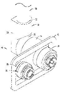
Fig. 1 is a perspective view of the wall hydrant of the
present invention connected to an inlet pipe;
Fig. 2 is an exploded view of the casing, connector,
hydrant body, vacuum breaker and valve assembly of the present
invention; and
Fig. 3 is a side view of the wall hydrant and connector.
DESCRIPTION OF THE PREFERRED EMBODIMENTS OF THE INVENTION
Referring to Fig. 1, the wall mounted hydrant assembly of
the present invention is referred to by reference numeral 10.
2a

CA 02521338 2007-06-12
As shown in Figures 1 to 3, the wall hydrant assembly has a
body 12 having a first passageway 14 and a second passageway
16. Extending between and fluidly connecting the first
passageway 14 to the second passageway 16 is a fluid conduit
18. Connected to the rearward end of the first passageway 14
is an L-shaped connector 20. The connector 20 has a first
portion 22 that is received within the rearward end of the
first passageway 14 and a second portion 24 that extends
substantially perpendicular to the first portion 22. The
first portion 22 is formed to fit snugly within the rearward
end of the first passageway 14 such that the first portion 22
rotates 360 within the rearward end of the first passageway
14 while maintaining a water tight seal. Extending from the
end of the second portion 24 through to the end of the first
portion 22 is a fluid conduit 26. The conduit 26 at the end of
the second portion 24 receives an inlet pipe 28 fluidly
connecting the body 12 to a fluid source.
Fitted within the forward end of the first passageway 14
is a conventional valve assembly 30 that seats against the
first portion 22 of the connector 20 to control the flow of
water from the inlet pipe 28 through the connector 20 to the
first passageway 14. Fitted within the forward end of the
second passageway 16 is a conventional vacuum breaker 32.
To install, the body 12 of the wall hydrant assembly 10 is
placed within a housing 34 having a back wall 36 with an
opening 38 such that the connector 20 extends through the
opening 38 of the back wall 36. The housing is mounted in a
wall in any conventional manner and optionally has a door 40
hingedly attached thereto to provide an aesthetically pleasing
decorative cover. The connector 20 is then rotated within the
rearward end of the first passageway 14 of the body 12 until
the connector is aligned with the inlet pipe 28. Once
aligned, the inlet pipe 28 is attached to the connector 20.
Because the connector 20 is rotatable within the rearward end
of the first
3

CA 02521338 2005-09-27
passageway 14, the connector 20 can be aligned with the inlet
pipe 28 regardless of the inlet pipe's 28 orientation to the
wall hydrant assembly.
It will be appreciated that those skilled in the art that
other various modifications could be made to the device without
departing from the spirit in the scope of this invention. All
such modifications and changes fall within the scope of the
claims and are intended to be covered thereby.
4

Dessin représentatif
Une figure unique qui représente un dessin illustrant l'invention.
États administratifs

2024-08-01 : Dans le cadre de la transition vers les Brevets de nouvelle génération (BNG), la base de données sur les brevets canadiens (BDBC) contient désormais un Historique d'événement plus détaillé, qui reproduit le Journal des événements de notre nouvelle solution interne.

Veuillez noter que les événements débutant par « Inactive : » se réfèrent à des événements qui ne sont plus utilisés dans notre nouvelle solution interne.

Pour une meilleure compréhension de l'état de la demande ou brevet qui figure sur cette page, la rubrique Mise en garde , et les descriptions de Brevet , Historique d'événement , Taxes périodiques et Historique des paiements devraient être consultées.

Historique d'événement

Description Date
Le délai pour l'annulation est expiré 2011-09-27
Lettre envoyée 2010-09-27
Accordé par délivrance 2009-02-03
Inactive : Page couverture publiée 2009-02-02
Inactive : Taxe finale reçue 2008-11-18
Préoctroi 2008-11-18
Un avis d'acceptation est envoyé 2008-10-15
Lettre envoyée 2008-10-15
Un avis d'acceptation est envoyé 2008-10-15
Inactive : Approuvée aux fins d'acceptation (AFA) 2008-09-26
Modification reçue - modification volontaire 2008-05-14
Inactive : Dem. de l'examinateur par.30(2) Règles 2007-11-26
Modification reçue - modification volontaire 2007-06-12
Inactive : Dem. de l'examinateur par.30(2) Règles 2007-01-11
Demande publiée (accessible au public) 2006-04-25
Inactive : Page couverture publiée 2006-04-24
Inactive : CIB en 1re position 2006-04-18
Inactive : CIB attribuée 2006-04-18
Modification reçue - modification volontaire 2005-12-30
Lettre envoyée 2005-11-10
Inactive : Certificat de dépôt - RE (Anglais) 2005-11-10
Lettre envoyée 2005-11-09
Demande reçue - nationale ordinaire 2005-11-09
Exigences pour une requête d'examen - jugée conforme 2005-09-27
Toutes les exigences pour l'examen - jugée conforme 2005-09-27

Historique d'abandonnement

Il n'y a pas d'historique d'abandonnement

Taxes périodiques

Le dernier paiement a été reçu le 2008-09-05

Avis : Si le paiement en totalité n'a pas été reçu au plus tard à la date indiquée, une taxe supplémentaire peut être imposée, soit une des taxes suivantes :

  • taxe de rétablissement ;
  • taxe pour paiement en souffrance ; ou
  • taxe additionnelle pour le renversement d'une péremption réputée.

Les taxes sur les brevets sont ajustées au 1er janvier de chaque année. Les montants ci-dessus sont les montants actuels s'ils sont reçus au plus tard le 31 décembre de l'année en cours.
Veuillez vous référer à la page web des taxes sur les brevets de l'OPIC pour voir tous les montants actuels des taxes.

Historique des taxes

Type de taxes Anniversaire Échéance Date payée
Requête d'examen - générale 2005-09-27
Enregistrement d'un document 2005-09-27
Taxe pour le dépôt - générale 2005-09-27
TM (demande, 2e anniv.) - générale 02 2007-09-27 2007-09-05
TM (demande, 3e anniv.) - générale 03 2008-09-29 2008-09-05
Taxe finale - générale 2008-11-18
TM (brevet, 4e anniv.) - générale 2009-09-28 2009-09-02
Titulaires au dossier

Les titulaires actuels et antérieures au dossier sont affichés en ordre alphabétique.

Titulaires actuels au dossier
WCM INDUSTRIES, INC.
Titulaires antérieures au dossier
WILLIAM T. BALL
Les propriétaires antérieurs qui ne figurent pas dans la liste des « Propriétaires au dossier » apparaîtront dans d'autres documents au dossier.
Documents

Pour visionner les fichiers sélectionnés, entrer le code reCAPTCHA :


Pour visualiser une image, cliquer sur un lien dans la colonne description du document. Pour télécharger l'image (les images), cliquer l'une ou plusieurs cases à cocher dans la première colonne et ensuite cliquer sur le bouton "Télécharger sélection en format PDF (archive Zip)" ou le bouton "Télécharger sélection (en un fichier PDF fusionné)".

Liste des documents de brevet publiés et non publiés sur la BDBC .

Si vous avez des difficultés à accéder au contenu, veuillez communiquer avec le Centre de services à la clientèle au 1-866-997-1936, ou envoyer un courriel au Centre de service à la clientèle de l'OPIC.


Description du
Document 
Date
(aaaa-mm-jj) 
Nombre de pages   Taille de l'image (Ko) 
Dessins 2005-09-26 3 43
Revendications 2005-09-26 1 22
Abrégé 2005-09-26 1 8
Description 2005-09-26 4 143
Dessin représentatif 2006-03-28 1 9
Description 2005-12-29 4 147
Revendications 2007-06-11 1 27
Description 2007-06-11 5 161
Revendications 2008-05-13 2 41
Description 2008-05-13 5 179
Accusé de réception de la requête d'examen 2005-11-08 1 176
Courtoisie - Certificat d'enregistrement (document(s) connexe(s)) 2005-11-09 1 106
Certificat de dépôt (anglais) 2005-11-09 1 158
Rappel de taxe de maintien due 2007-05-28 1 112
Avis du commissaire - Demande jugée acceptable 2008-10-14 1 163
Avis concernant la taxe de maintien 2010-11-07 1 171
Taxes 2007-09-04 1 50
Correspondance 2008-11-17 1 53
Taxes 2008-09-04 1 51