Note : Les descriptions sont présentées dans la langue officielle dans laquelle elles ont été soumises.
CA 02522741 2010-04-19
1
Method and Device for Breaking Separation of Bearing Caps
Technical Field
The present invention relates to a method and device for the breaking or
fracture
separation of at least one bearing cap from a corresponding thrust block in
the bearing
assembly of engine cases provided with bearing bores which are arranged in-
line, in
particular crankshaft cases for reciprocating piston engines.
Prior Art
The known types of method and device usually involve the introduction of an
extension
mandrel comprising two half-mandrels into one or more bearing bores and the
fracture
separation force for _ separating the bearing cap from the thrust block.. is
produced by
spreading the two half-mandrels apart in a force-actuated manner.
This spreading-apart process is usually brought about by mechanically or
hydraulically
driving a separating wedge (cf. for example U.S. patent 4,684,267 or Fig. 1 of
DE 44 13
255) or by positioning a hydraulically impacted expander between the half-
mandrels. In
addition, expanders in the form of knuckle-joint assemblies are used (cf. for
example
DE 199 18 067).
It is also known to clamp the thrust block securely to a stationary support
and to "sever"
the bearing cap in a controlled manner by introducing a tensile force (cf.
Fig. 2 of DE 44
13 255). For this purpose, a tie-rod half is placed within the bearing bore in
the area of the
bearing cap and this half-tie rod is attached, at both sides of the bearing
cap, to tensioning
tabs which are connected to a hydraulic pulling means that produces the
tensile force
needed to "sever" the bearing cap.
As a rule, breaking or fracture separation entails the problem of so-called
bending strain.
Such deformation phenomena are due to the fact that, during the breaking
separation
process, the fracture cannot be realized absolutely synchronously across the
entire
breaking separation face. On the contrary, the fracture begins at a point on
the breaking
separation face and propagates across the entire breaking separation face with
a time delay
CA 02522741 2010-04-19
2
(in the millisecond range). The already detached part bends up with respect to
the part not
yet separated, thus causing the breaking separation faces to be no longer
fitted precisely
together after the fracture has occurred. This effect arises particularly
noticeably whenever
bearing bores or bearing sleeves, the breaking separation face of which is
formed by two
spaced-apart surface portions, undergo fracture separation. Workpieces that
exhibit these
deformation phenomena do not comply with quality-related demands specified in
bearing
or engine construction and are consequently useless.
The prior art counters this type of bending strain in that the parts to be
separated are
flexibly pressed together at a specific pre-tension. This pre-tension must,
however, be
overcome during the breaking separation process, because it counteracts the
force of
fracture separation. To reduce bending strain to an economically viable degree
whenever
bearing assemblies undergo fracture separation, it will be necessary in
practice to operate
at relatively high pre-tensions and consequently with very high fracture-
separation forces,
too.
Description of the Invention
It is the object of the present invention to provide a method and device for
the breaking
separation of bearing assemblies that permit the fracture face to exhibit
enhanced
properties.
This object is solved in accordance with the invention by a method and device
for the
breaking separation of bearing assemblies.
The present invention is based on the idea of improving the properties of
fracture faces
during breaking separation in that the bending strains that arise during
fracture separation
are reduced as far as possible. For this purpose, a completely novel approach
is chosen by
the invention while retaining the tried-and-tested extension mandrel system
that comprises
two half-mandrels which can be moved apart. Instead of fixing the
corresponding bearing
cap by way of a pre-tension, the fixing procedure is performed by a special
clamping
system. In accordance with the invention, the bearing cap is therefore secured
against
rotation, but is clamped in a manner that offers a limited degree of free
movement - in the
direction of breaking separation - between the corresponding half-mandrel and
a fixing
means.
In principle, this clamping system consists of the half-mandrel that
corresponds to the
bearing cap, and a fixing means, between which the bearing cap is fixed in a
non-movable
CA 02522741 2005-10-18
3
manner. The crux of the invention lies in the fact that this unit, consisting
of the half-
mandrel, bearing cap and fixing means, is supported in such a way that
although the
bearing cap cannot rotate, it can move freely to a limited degree in the
direction of
breaking separation. This makes it superfluous to use pre-tensions that have
to be
overcome by the respective breaking separation force. As a result, it is
possible to work
using relatively low breaking separation forces, which enables the device
according to the
invention to have a simple and relatively lightweight structural design.
Devices that operate on the basis of the principle described above can as a
rule be
designed in a very wide variety of ways. Nonetheless, a device that has a
particularly
simple structure in technical terms, yet which permits reliable and effective
clamping, is
obtained as a result of the fact that at least two gripping means that can be
coupled, on
both sides of the corresponding bearing cap, to a half-mandrel corresponding
to the
bearing cap are provided, and the corresponding bearing cap can be clamped,
via a fixing
means securely connected to the gripping means, between the corresponding half-
mandrel
and the fixing means in such a way that a unit consisting of the corresponding
half-mandrel with the gripping means as well as the fixing means and the
clamped bearing
cap is freely movable to a limited degree in the direction of fracture
separation, though
this unit is supported in a manner secured against rotation. As a result, the
corresponding
bearing cap is prevented from rotating with respect to the thrust block during
fracture
separation, thereby largely ruling out bending strain.
In this way, the above-described disadvantages encountered in the prior art
can be
eliminated and the properties of the fracture surface can be enhanced
considerably. It is
particularly beneficial for the device according to the invention not to apply
any external
forces, which counteract the breaking separation process, to those components
which are
to be separated. This means that those fracture forces which are to be applied
are slight,
thus facilitating the breaking process and thereby making it even easier to
design the
device structure.
In principle, the gripping means can be formed and coupled to the
corresponding
half-mandrel in an arbitrary fashion. It is, however, an advantage for the
extension
mandrel, especially the corresponding half-mandrel, to comprise at least one
recess that is
adapted to the gripping means or for it to comprise at least one projection,
with which the
gripping means engage. This is a simple way of producing a reliable form-fit
that helps to
ensure the desired, rotationally secured arrangement of bearings.
Particularly in the case of rigid gripping means, an extension of the present
invention
makes it preferable to provide the corresponding half-mandrel with
tangentially extending
CA 02522741 2005-10-18
= 4
insertion slots on its periphery at mutually facing sides; these insertion
slots can be used to
slide the corresponding gripping means over the half-mandrel. Particular
preference is
given to placing the insertion slots in communication with the at least one
recess so that
the gripping means can engage rapidly and reliably with the at least one
recess via the
insertion slots.
In the case of such a structural design, it is an advantage for the at least
one recess to be
arranged axially adjacent to the insertion slots and for this recess to merge
directly into
these slots. In such a structural design, the gripping means can slide,
through the insertion
slots, over the corresponding half-mandrel and the act of coupling can be
achieved by
simply sliding the half-mandrel in an axial direction. The movement in an
axial direction
does in fact enable the gripping means to engage with the recesses disposed
axially
adjacent to the insertion slots, thus causing the gripping means to interlock
positively with
the corresponding half-mandrel.
A configuration that is particularly simple in technical terms and which
exhibits static
rigidity is obtained when the gripping means are formed by pincers which
preferably each
comprise fixed jaws, i.e. jaws which do not move against one another and
which, in the
region of their ends, have engagement members that face towards one another
and which
engage with the at least one recess in the corresponding half-mandrel.
The fixing means, too, may be designed in a very wide variety of ways. An
especially
simple and effective layout is obtained when the fixing means has at least one
force-
actuated detent. This approach enables the fixing means to be tensioned
reliably with the
bearing cap that is to be separated and with the corresponding half-mandrel.
Preference is
given to providing at least two spaced-apart detents (32, 34) that act in a
particularly
preferred manner upon the bearing cap at that side which is opposite the
corresponding
half-mandrel. This approach produces a unit that is in itself tensioned and
consists of the
fixing means, bearing cap that is to be separated and the corresponding half-
mandrel,
without forces that impede subsequent fracture separation from being
introduced into the
bearing assembly as a result of tensioning. At the same time, the detents can
be realized in
a simple and economically viable manner, for example by means of hydraulic
cylinders or
the like.
Short Description of the Drawings
Fig. 1 shows a schematic perspective view of a preferred embodiment of the
breaking separation device in accordance with the invention;
CA 02522741 2005-10-18
Figs. 2 to 6 each schematically show individual steps of a preferred
embodiment of the
breaking separation method in accordance with the invention, which method
makes use of the device shown in Fig. 1.
Detailed Description of Preferred Embodiments
Preferred embodiments of the present invention will now be described in detail
with
reference to Figs. 1 to 6. Identical reference numbers in the drawings each
designate
identical components.
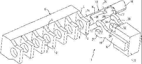
Fig. 1 depicts schematically a perspective view of a preferred embodiment of a
device 1
for breaking separation in accordance with the present invention. As can be
identified in
Fig. 1, the device 1 in the present embodiment is used to machine, in a
breaking
separation manner, a crankshaft case 6, as used for example in combustion
engines. The
crankshaft case 6 has a series of bearing bores 8 that are arranged in-line
and which are
each enclosed by a thrust block 4 and a bearing cap 2 that are intended to be
separated
from one another by means of breaking separation. During the breaking
separation
process, the crankshaft case 6 can be supported in a suitable manner. It must
be borne in
mind, however, that the present invention is not limited to the illustrated
application, but
may also be applied to other bearing aseemblies or the like.
To begin with, the breaking separation device shown in Fig. 1 comprises an
extension
mandrel 10 that has two half-mandrels 12, 14 and can be inserted into at least
one of the
in-line bearing bores 8. An expander 16 for moving the half-mandrels 12, 14
apart is
interposed between the half-mandrels 12, 14. The expander 16 may, for example,
be
formed by a wedge or a hydraulic means that is capable of applying sufficient
expansion
force to the half-mandrels 12, 14.
The breaking separation device 1 also comprises two gripping means in the form
of
pincers 18, 20 that can be coupled, at both sides of the corresponding bearing
cap 2, to the
half-mandrel 12 that corresponds to the bearing cap 2. The pincers 18 are
securely
connected to a fixing means 22 that is freely movable to a limited degree, but
which is
supported in a manner that is secured against rotation, in the direction of
breaking
separation, that is to say in a direction essentially perpendicular to the
axis of the bearing
bores 8. Such a manner of support can be realized, for example, as a kind of
sliding sleeve
or the like.
In the present embodiment, the half-mandrel 14, which faces away from the
corresponding bearing cap 2, has two recesses 24 so that the half-mandrel 12,
which faces
CA 02522741 2005-10-18
6
towards the corresponding bearing cap 2, protrudes like a projection above the
other
half-mandrel 14. This makes it possible for the pincers 18, 20 to engage
positively with
the half-mandrel 12 that is mated with the corresponding bearing cap 2.
Furthermore, the half-mandrel 12 that is mated with the corresponding bearing
cap 2 has,
at its periphery on mutually facing sides, tangentially extending insertion
slots 26 for the
pincers 18, 20 that are each in communication with the recesses 24. In more
precise terms,
the recesses 24, when viewed in the axial direction of the extension mandrel
10, are each
located axially adjacent to the insertion slots 26 and merge into them.
In the present embodiment, the pincers 18, 20 are formed such as to have a
stationary or
rigid geometry. The pincers 18, 20 each comprise two fixed jaws 28 that are
arranged
essentially in a U shape and each have on their inner periphery a tooth-like
engagement
member 30 facing towards one another in the case of each pincer 18, 20.
As can be identified in Fig. 1, the thickness of the pincers 18, 20
corresponds essentially
to the width of the insertion slots 26, thereby enabling the pincers 18, 20 to
be guided onto
the extension mandrel 10 such that the engagement members 30 end up form-
locked in the
region of the recesses 24 and can engage behind the corresponding projection
of the half-
mandrel 12.
In the present embodiment, the fixing means 22 comprises two force-actuated
detents 32,
34, the detent 34 being hidden by the pincer 18 in Fig. 1. The detents 32, 34
are spaced
apart from one another and are provided between the pincers 18, 20 such as to
face
towards the corresponding bearing cap 2. With regard to an even application of
load, it is
preferred that the detents 32, 34 are located roughly mid-way between the
pincers 18, 20
and extend essentially parallel thereto. The force-actuated detents 32, 34
may, for
example, be protractable pistons of hydraulic or pneumatic cylinders. It goes
without
saying, however, that other suitable limit stop members can be used, too,
within the
framework of the present invention. In addition, it is conceivable that the
detents do not
move and that the pincers are force-actuated.
The operation of the breaking separation device 1 depicted in Fig. 1 will now
be
described, by way of example, on the basis of Figs. 2 to 6, which each
schematically
illustrate individual steps of a preferred embodiment of the breaking
separation method
according to the invention, in which the device shown in Fig. 1 is used.
Starting out from the state shown in Fig. 1, the extension mandrel 10, in its
relaxed state,
i.e. without any considerable expansion force being applied to the half-
mandrels 12, 14 by
CA 02522741 2005-10-18
7
the expander 16, is first introduced into the first bearing bore 8 in such a
way that at least
the first insertion slot 26 ends up between the first and the second bearing
cap 2 (Fig. 2,
with that bearing cap which is located on the right side in the drawings being
designated
as the first bearing cap). The insertion slots 26 are preferably moved into
such a position
that they are essentially in alignment with the pincers 18, 20 of the fixing
means 22.
As can be seen in Fig. 3, the securely connected unit consisting of the
pincers 18, 20 and
the fixing means 22 is now moved towards the extension mandrel 10 and the
crankshaft
case 6 such that the pincers 18, 20, with their jaws 28 and particularly their
tooth-like
engagement members 30, plunge into the insertion slots 26. The pincers 18, 20
are moved
towards the extension mandrel 10 to such an extent that the tooth-like
engagement
members 30 end up axially adjacent to the recesses 24.
In the next step, as shown in Fig. 4, the extension mandrel 10 is introduced
further into the
bearing bore 8. The tooth-like engagement members 30 of the pincers 18, 20
assume
form-locked engagement with the recesses 24 of the extension mandrel 10 and
therefore
engage behind the extension sleeve 12 that faces towards the bearing block 2
that is to be
separated. In other words, a positive transmission of power is now possible
between the
extension sleeve 12 that faces towards the bearing cap 2 which is to be
separated, and the
pincers 18, 20.
The force-actuated detents 32, 34 are then protracted such as to come in
contact with the
facing surface 2' of the bearing cap 2 that is to be separated and such as to
apply a force
thereto (Fig. 5). This produces a pre-tension that securely tensions the
fixing means 22,
the pincers 18, 20, the extension sleeve 12 that faces towards the bearing cap
2 that is to
be separated, and the bearing cap 2 itself that is to be separated, to form a
unit. Together
with the bearing arrangement of the fixing means 22 - which arrangement is
secured
against rotation, but which moves freely to a limited degree - this approach
reduces or
largely eliminates, during the fracture separation process, any twisting or
bending strain
that affects the bearing cap 2 that is to be separated. In this way, a
fracture surface can be
obtained with a much improved quality and surface structure.
Finally, as can be identified in Fig. 6, the actual breaking separation
process is performed.
For this purpose, the half-mandrels 12, 14 are moved so far apart by means of
the
expander 16 until a separation fracture is obtained between the bearing cap 2
and the
corresponding thrust block 4. Within the scope of the present invention, it is
unnecessary
to apply tensile forces via the fixing means 22 to the bearing cap 2 that is
to be separated,
because, in the present embodiment, the fixing means 22 with the pincers 18,
20 and the
detents 32, 34 serves merely to prevent twisting of the bearing cap 2 that is
to be
CA 02522741 2005-10-18
8
separated, but it does not serve to impede or assist the bearing cap's
movement in the
direction of breaking separation.
After the breaking separation process is complete, the clamping of the
separated bearing
cap 2 can be released by retracting the detents 32, 34, with the result that
the separated
bearing cap 2 can be removed and the pincers 18, 20 disengaged from the
extension
mandrel 10 by retracting same and then retracting the pincers 18, 20. The
aforementioned
process can then be performed analogously for the next bearing cap 2.
Although the above-described embodiment example of the present invention
relates to the
breaking separation of a single bearing cap 2, the present invention does, of
course, make
it possible to separate a plurality of bearing caps 2 from the corresponding
thrust block 4
during a breaking separation process. In this respect, it may be useful to
provide, for
example, a plurality of fixing means 22 having corresponding pincers or to
equip a single
fixing means 22 with a plurality of pincers and corresponding detents.