Sélection de la langue

Search

Sommaire du brevet 2524301 

Énoncé de désistement de responsabilité concernant l'information provenant de tiers

Une partie des informations de ce site Web a été fournie par des sources externes. Le gouvernement du Canada n'assume aucune responsabilité concernant la précision, l'actualité ou la fiabilité des informations fournies par les sources externes. Les utilisateurs qui désirent employer cette information devraient consulter directement la source des informations. Le contenu fourni par les sources externes n'est pas assujetti aux exigences sur les langues officielles, la protection des renseignements personnels et l'accessibilité.

Disponibilité de l'Abrégé et des Revendications

L'apparition de différences dans le texte et l'image des Revendications et de l'Abrégé dépend du moment auquel le document est publié. Les textes des Revendications et de l'Abrégé sont affichés :

  • lorsque la demande peut être examinée par le public;
  • lorsque le brevet est émis (délivrance).
(12) Demande de brevet: (11) CA 2524301
(54) Titre français: ELEMENT D'AFFINAGE
(54) Titre anglais: REFINING ELEMENT
Statut: Réputée abandonnée et au-delà du délai pour le rétablissement - en attente de la réponse à l’avis de communication rejetée
Données bibliographiques
Abrégés

Abrégé français

L'invention concerne un élément d'affinage utilisé dans des dispositifs d'affinage en forme de disque servant à travailler des matériaux fibreux, ledit élément (10) d'affinage étant formé d'un ensemble de barres (11) avec des surfaces supérieures (13), des surfaces latérales (14), et des rainures intermédiaires (12). Une pluralité de cavités (18) sont situées les unes derrières les autres sur les bords longitudinaux (15) des barres (11), lesdites cavités étant ouvertes sur la surface supérieure (13) et sur une surface latérale (14) des barres.


Abrégé anglais


Refining element intended for refiners of disc-type for working fibrous
material, where the refining element (10) is formed with a pattern of bars
(11) with upper surfaces (13) and side surfaces (14) and intermediate grooves
(12). A plurality of recesses (18) are arranged one after the other in
longitudinal edges (15) of the bars (11), which recesses are open both to the
upper surface (13) and one side surface (14) of the bars.

Revendications

Note : Les revendications sont présentées dans la langue officielle dans laquelle elles ont été soumises.


5
Claims
1. A refining element intended for refiners of disc-type for working fibrous
material, where the refining element (10) is formed with a pattern of bars
(11) with
upper surfaces (13) and side surfaces (14) and intermediate grooves (12),
characterized in that a plurality of recesses (18) are arranged one after the
other in
longitudinal edges (15) of the bars (11), that the recesses are open both to
the upper
surface (13) and one side surface (14) of the bars.
2. A refining element as defined in claim 1, characterized in that the
recesses (18) are provided only on one side of the bars (11).
3. A refining element as defined in claim 1, characterized in that the
recesses (18) are provided on both sides of the bars (11).
4. A refining element as defined in any one of the preceding claims,
characterized in that the recesses (18) extend inward to about the centre of
the upper
surface (13) of the bars.
5. A refining element as defined in any one of the preceding claims,
characterized in that the recesses (18) have a depth of 2-5 mm, counted from
the
edge (15) of the bar.
6. A refining element as defined in any one of the preceding claims,
characterized in that the recesses (18) have a width of 2-5 mm.
7. A refining element as defined in any one of the preceding claims,
characterized in that the distance between recesses (18) is 1-10 mm.
8. A refining element as defined in any one of the preceding claims,
characterized in that the recesses (18), counted in the flow direction of the
material,
form an angle of between 45° and 90° with the bar (11).
9. A refining element as defined in claim 5, characterized in that the
recesses (18) are arranged substantially across the bars (11).

Description

Note : Les descriptions sont présentées dans la langue officielle dans laquelle elles ont été soumises.

CA 02524301 2005-10-31
WO 2004/103567 PCT/SE2004/000678
Refining element
This invention relates to refiners of disc-type with opposed refining discs
rotating
relative to one another. The refining discs are provided with refining
elements, which
between themselves form a refining gap with a refining zone for working
fibrous
material. The fibrous material preferably is lignocellulosic fibrous material
and the
refiner is used for the manufacture of, for example, reject pulp, recycled
fibre pulp and
mechanical pulps, such as board pulp, thermomechanical pulp (TMP) and chemi-
thermo-mechanical pulp (CTMP) and for low-concentration refining chemical
pulps.
The invention, more precisely, relates to a refining element for use in a
refiner of the
above kind.
A refining element is formed with a pattern of bars and intermediate grooves.
The bars
and grooves are formed in different ways, depending on which fibrous material
is
worked and which refining degree and, thus, in the case of lignocellulosic
material,
which pulp quality are desired. The bars have an upper surface and side
surfaces so
that longitudinal edges are formed between the upper surface and respective
side
surface. The bars can be, for example, continuous or discontinuous and be
arranged
in different patterns. The working of the fibrous material substantially is
carried out by
the bars of the refining elements. The refining gap is formed so that the
fibrous
material, seen in radial direction, shall pass from the inside outward.
Farthermost
inward in the refining gap the refining elements normally are formed so as to
bring
about a first disintegration of the material and to advance the material
outward in the
refining gap. A certain defibering, i.e. separation of the fibers of the
lignocellulosi6
material, also takes place in the inner portion of the refining gap where the
distance
between the refining surfaces is the greatest. Thereafter the distance
decreases
outward in order that the desired working or refining of the fibrous material
shall be
obtained.
At the refining of fibrous material of high concentration, and above all at
high energy
inputs, it was found necessary to place flow restrictions, so-called dams, in
the grooves
of the refining elements in order to prevent unworked material from passing
out through
the refining gap. These dams, however, form an obstacle for the steam
developing in
the refining gap during the refining. A high steam pressure is thereby created
in the

CA 02524301 2005-10-31
WO 2004/103567 PCT/SE2004/000678
refining gap. The high steam pressure has a negative effect on the capacity
and
operational stability of the refiner. It also implies a limitation of the
possible energy
input. The developed steam, thus, will be forced by the flow restrictions
upward out of
the grooves and disturb the material flow through the refining gap.
One way of solving this problem would be to supply dilution water to the
refining gap in
order thereby to condense the steam. This, however, results in reducing the
material
conc.~ntration to a low level and thereby deteriorated pulp quality.
At the working or refining of fibrous material with low concentration no steam
development takes place, and the material is transported partially by the
liquid flow out
of the refining gap. Also here usually dams are used to prevent unworked
material from
passing out through the refining gap. It can imply, however, that the flow
through the
refining gap will be much too low.
The present invention offers a solution of the above problems. According to
the
invention, the bars are provided with a plurality of recesses, which are
arranged in the
longitudinal edges of the bars. The recesses shall be directed across the bars
or so as
to form an angle of at least 45° with the bars. The recesses are open
both to the upper
surface of the bars and to one side surface or both side surfaces. By this
configuration
of the bars the flow of the fibrous material through the refining gap will be
braked, so-
that the stay-time of the fibers in the refining gap will be longer and the
working thereby
be increased, without braking the steam or liquid flow in the grooves between
the bars
so that the flow of the fibrous material is disturbed.
The recesses can be placed, for example, along the entire length of the bars
or be
broken off by small portions without recesses, counted in the longitudinal
direction of
the bars. Each recess can have a constant or varying depth along the bars in
the upper
surface and side surfaces of the bars. The recesses can be formed only on one
side or
on both sides of the bars.
When the recesses are formed only on one side of the bars, the rotation
direction of the
refining discs carrying the refining elements cannot be changed. Such a
configuration,
however, can still be suitable with a view to strength.

CA 02524301 2005-10-31
WO 2004/103567 PCT/SE2004/000678
3
The characterizing features of the invention are apparent from the attached
claims.
The invention is described in greater detail in the following, with reference
to the
accompanying Figures illustrating some embodiments of the invention.
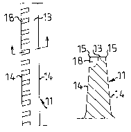
Fig, 1 shows the front side of a refining segment with a pattern of bars and
intermediate grooves;
Figs. 2 and 3 show the upper surface of the bars with different
configurations;
Figs. 4 and 5 are cross-sections of two alternatives according to Fig. 2.
In Fig. 1 is shown a refining element 10 intended for refining fibrous
material with high
concentration. The refining element 10 is provided with a pattern of bars 11
and'
intermediate grooves 12, where the bars have upper surfaces 13 and side
surfaces 14
with edges 15. The pattern is divided into two zones, an inner zone 16 and an
outer
zone 17, where the bars and grooves in the inner zone are coarser than in the
outer
zone. The bars in the inner zone are intended to bring about a first
disintegration of the
material and to advance the material outward to the outer zone. The bars in
the outer
zone are placed more tightly, which yields more bar edges for effecting the
substantial
working and refining of the material. The pattern can also comprise more
zones, where
the pattern usually is made tighter from zone to zone, seen radially outward.
In Fig. 2 is shown an embodiment of a bar 11 on a refining element according
to the
invention. Along the bar 11 a plurality of recesses 18 are placed. The
recesses are
arranged slightly angular in relation to the longitudinal direction of the
bars and are
open both to the upper surface 13 and side surface 14. The recesses suitably
can
extend to about the centre of the upper surface of the bar. The depth of the
recesses,
counted from the edge, shall be one or some millimetres, preferably 2-5 mm.
The width
should also be one or some millimetres, preferably 2-5 mm. Bars thereby get
toothed
edges. The distance between adjacent recesses should be 1-10 mm, preferably 2-
5
mm.
In Fig. 3 is shown another embodiment of a bar 11. Differently from Fig. 2 the
recesses
18 are here placed in both edges 15 of the bar, so that both edges of the bar
are

CA 02524301 2005-10-31
WO 2004/103567 PCT/SE2004/000678
toothed. As regards the configuration of the recesses, the same dimensions
apply as in
Fig. 2. The recesses on opposed edges 15 are in this case suitably offset, so
that they
do not lie directly in front of each other. This implies that a refining
element with such
bars can rotate in both directions.
The form of the bottom of the recesses 15 can be rectilinear, as shown in Fig.
4, or
curved, as shown in Fig. 5. Other forms, of course, can be imagined. The
recesses
shall be arranged across the bars or form an angle of at least 45° with
the longitudinal
direction of the bars. This applies above all to the surface, which outwardly
defines a
recess 18, counted in the flow direction of the material. When the recesses 18
are
angular, they should extend from the side surfaces 14 obliquely outward,
counted in
the flow direction of the material.
Bars with a configuration according to the invention can be placed on any zone
on the
refining element, but preferably in an outer zone where the working and
refining are
most intensive and the distance between opposed refining elements is the
shortest, i.e.
the refining gap is the smallest and the steam development the greatest.
The invention, of course, is not restricted to the embodiments shown, but can
be varied
within the scope of the claims with reference to description and Figures.

Dessin représentatif
Une figure unique qui représente un dessin illustrant l'invention.
États administratifs

2024-08-01 : Dans le cadre de la transition vers les Brevets de nouvelle génération (BNG), la base de données sur les brevets canadiens (BDBC) contient désormais un Historique d'événement plus détaillé, qui reproduit le Journal des événements de notre nouvelle solution interne.

Veuillez noter que les événements débutant par « Inactive : » se réfèrent à des événements qui ne sont plus utilisés dans notre nouvelle solution interne.

Pour une meilleure compréhension de l'état de la demande ou brevet qui figure sur cette page, la rubrique Mise en garde , et les descriptions de Brevet , Historique d'événement , Taxes périodiques et Historique des paiements devraient être consultées.

Historique d'événement

Description Date
Demande non rétablie avant l'échéance 2011-05-05
Le délai pour l'annulation est expiré 2011-05-05
Réputée abandonnée - omission de répondre à un avis sur les taxes pour le maintien en état 2010-05-05
Lettre envoyée 2009-05-12
Modification reçue - modification volontaire 2009-04-01
Requête d'examen reçue 2009-04-01
Toutes les exigences pour l'examen - jugée conforme 2009-04-01
Exigences pour une requête d'examen - jugée conforme 2009-04-01
Inactive : Page couverture publiée 2006-02-15
Inactive : CIB en 1re position 2006-02-14
Lettre envoyée 2006-01-05
Inactive : Notice - Entrée phase nat. - Pas de RE 2006-01-05
Demande reçue - PCT 2005-12-02
Exigences pour l'entrée dans la phase nationale - jugée conforme 2005-10-31
Demande publiée (accessible au public) 2004-12-02

Historique d'abandonnement

Date d'abandonnement Raison Date de rétablissement
2010-05-05

Taxes périodiques

Le dernier paiement a été reçu le 2009-04-24

Avis : Si le paiement en totalité n'a pas été reçu au plus tard à la date indiquée, une taxe supplémentaire peut être imposée, soit une des taxes suivantes :

  • taxe de rétablissement ;
  • taxe pour paiement en souffrance ; ou
  • taxe additionnelle pour le renversement d'une péremption réputée.

Les taxes sur les brevets sont ajustées au 1er janvier de chaque année. Les montants ci-dessus sont les montants actuels s'ils sont reçus au plus tard le 31 décembre de l'année en cours.
Veuillez vous référer à la page web des taxes sur les brevets de l'OPIC pour voir tous les montants actuels des taxes.

Historique des taxes

Type de taxes Anniversaire Échéance Date payée
Enregistrement d'un document 2005-10-31
TM (demande, 2e anniv.) - générale 02 2006-05-05 2005-10-31
Taxe nationale de base - générale 2005-10-31
TM (demande, 3e anniv.) - générale 03 2007-05-07 2007-04-24
TM (demande, 4e anniv.) - générale 04 2008-05-05 2008-04-22
Requête d'examen - générale 2009-04-01
TM (demande, 5e anniv.) - générale 05 2009-05-05 2009-04-24
Titulaires au dossier

Les titulaires actuels et antérieures au dossier sont affichés en ordre alphabétique.

Titulaires actuels au dossier
METSO PAPER, INC.
Titulaires antérieures au dossier
NILS VIRVING
Les propriétaires antérieurs qui ne figurent pas dans la liste des « Propriétaires au dossier » apparaîtront dans d'autres documents au dossier.
Documents

Pour visionner les fichiers sélectionnés, entrer le code reCAPTCHA :


Pour visualiser une image, cliquer sur un lien dans la colonne description du document. Pour télécharger l'image (les images), cliquer l'une ou plusieurs cases à cocher dans la première colonne et ensuite cliquer sur le bouton "Télécharger sélection en format PDF (archive Zip)" ou le bouton "Télécharger sélection (en un fichier PDF fusionné)".

Liste des documents de brevet publiés et non publiés sur la BDBC .

Si vous avez des difficultés à accéder au contenu, veuillez communiquer avec le Centre de services à la clientèle au 1-866-997-1936, ou envoyer un courriel au Centre de service à la clientèle de l'OPIC.


Description du
Document 
Date
(aaaa-mm-jj) 
Nombre de pages   Taille de l'image (Ko) 
Revendications 2005-10-30 1 40
Dessins 2005-10-30 1 36
Description 2005-10-30 4 191
Abrégé 2005-10-30 1 53
Dessin représentatif 2005-10-30 1 4
Description 2009-03-31 5 213
Revendications 2009-03-31 1 45
Avis d'entree dans la phase nationale 2006-01-04 1 192
Courtoisie - Certificat d'enregistrement (document(s) connexe(s)) 2006-01-04 1 104
Rappel - requête d'examen 2009-01-05 1 118
Accusé de réception de la requête d'examen 2009-05-11 1 175
Courtoisie - Lettre d'abandon (taxe de maintien en état) 2010-06-29 1 172
PCT 2005-10-30 3 104