Sélection de la langue

Search

Sommaire du brevet 2524540 

Énoncé de désistement de responsabilité concernant l'information provenant de tiers

Une partie des informations de ce site Web a été fournie par des sources externes. Le gouvernement du Canada n'assume aucune responsabilité concernant la précision, l'actualité ou la fiabilité des informations fournies par les sources externes. Les utilisateurs qui désirent employer cette information devraient consulter directement la source des informations. Le contenu fourni par les sources externes n'est pas assujetti aux exigences sur les langues officielles, la protection des renseignements personnels et l'accessibilité.

Disponibilité de l'Abrégé et des Revendications

L'apparition de différences dans le texte et l'image des Revendications et de l'Abrégé dépend du moment auquel le document est publié. Les textes des Revendications et de l'Abrégé sont affichés :

  • lorsque la demande peut être examinée par le public;
  • lorsque le brevet est émis (délivrance).
(12) Brevet: (11) CA 2524540
(54) Titre français: TOLE PERFOREE STRATIFIEE
(54) Titre anglais: LAMINATED SCREEN PLATE
Statut: Accordé et délivré
Données bibliographiques
(51) Classification internationale des brevets (CIB):
  • B07B 1/46 (2006.01)
  • B23P 15/12 (2006.01)
  • B32B 15/01 (2006.01)
(72) Inventeurs :
  • DAVIS, STEPHEN KERR (Australie)
  • FERENCZ, JOSEPH (Australie)
  • KEMPE, PHILIP (Canada)
(73) Titulaires :
  • CQMS PTY LTD
(71) Demandeurs :
  • PAC MINING PTY LTD (Australie)
(74) Agent: SMART & BIGGAR LP
(74) Co-agent:
(45) Délivré: 2008-07-29
(22) Date de dépôt: 2005-10-26
(41) Mise à la disponibilité du public: 2006-05-01
Requête d'examen: 2005-10-26
Licence disponible: S.O.
Cédé au domaine public: S.O.
(25) Langue des documents déposés: Anglais

Traité de coopération en matière de brevets (PCT): Non

(30) Données de priorité de la demande:
Numéro de la demande Pays / territoire Date
2004906256 (Australie) 2004-11-01

Abrégés

Abrégé français

La présente concerne une tôle perforée de construction multicouche comprenant un élément structural pourvu d'un certain nombre d'ouvertures et d'une couche protectrice faite d'un matériau à résistance élevée à l'usure comportant des ouvertures correspondantes à celles de l'élément structural. Ce dernier peut de préférence être dénommé plaque de support, et la tôle perforée est de préférence stratifiée.


Abrégé anglais

A screen plate of multilayer construction including a structural member containing a plurality of openings and provided with a protective layer of highly wear resistant material with openings corresponding with those in the structural member. The structural member preferably could be referred to as a carrier plate and preferably the screen plate is a laminated screen plate.

Revendications

Note : Les revendications sont présentées dans la langue officielle dans laquelle elles ont été soumises.


6
CLAIMS
1. A screen plate of multilayer construction including a structural member
forming a steel carrier plate containing a plurality of openings and provided
with a
protective layer of highly wear resistant material with openings corresponding
with
those in the structural member, wherein the protective layer of highly wear
resistant material consists of a multiplicity of relatively small plates
shaped and
arranged on the carrier plate in such a way they form a mosaic with the
openings in
each small plate matching the openings in the carrier plate.
2. A screen plate as defined in claim 1 wherein the small plates of highly
wear
resistant material are each an alloy white iron brazed to a mild steel backing
plate.
3. A screen plate as defined in claim 2 wherein the openings in the small
plates
of highly wear resistant material overlap the openings in the carrier plate.
4. A screen plate as defined in claim 3 wherein the plates of highly wear
resistant material are welded to the carrier plate by welding to the
overlapped
portion of the openings in the mild steel backing plate.

Description

Note : Les descriptions sont présentées dans la langue officielle dans laquelle elles ont été soumises.

CA 02524540 2005-10-26
1
TITLE
LAMINATED SCREEN PLATE
This invention relates to screen plates, particularly in the mining and
associated
industries.
S BACKC,ROUND
In the mining and associated industries screen plates are used to separate
smaller
grades of the material passing over the n plate or breaker screens, which may
either be a flat vibratory piste or an arcuate plate do form portion of a
rotating
cylindrical drum.
Conventionally screen plates comprise a metal plate having a plurality of
holes
there through of the required size, which may be in one example of the order
of
50mm square to permit material of smaller size to pass there through from
larger
rocks and boulders passing over the screen plate. In one example breaker
screens form the screening surface of a large rotating drum of a diameter of
some 5
1 S meters with a screening length about 17 meters, the drum having a
throughput of
about 2 million tonnes per month.
The screen plates are typically metal plates 50mm thick with 50mrn square
holes
forming the perforated plate. Each plate is typically about 1.8 meters square
weighing over 1 tonne. The wearing surtace of the perforated plate has a hard
facing of plasma transfer arc welded tungsten carbide to a depth of 2-3 mm. In
use
the impact of large rocks of up to 300mm diameter causes spalling of the hard
and
brittle tungsten carbide thereby adversely affecting service life.
Hence it is an object of the invention to overcome one or more of the
deficiencies
of the prior wear resistant screen plates.
Z 5 A further object of the invention is to provide a material separation
member having
abrasion resistant qualities.
A further object of the invention is to provide a material separation member
possessing a wear resistant surface provided with perforations.

CA 02524540 2005-10-26
Z
A further object is to provide a mineral separation member constructed in such
a
way that the surface between the holes is covered by an assembly of wear
plates
that protirds ail surfaces in contact with the material passing through.
BRIEF STATEMENT OF THE INVENTION
S Thus there is provided aooonding to the invention a scxeen plate of
multllayer
construction comprising a structural member, referred to henceforth as a
carrier plate,
containing a plurality of openings and provided with a protective layer of
highly
wear resistant material with openings corresponding with those in the carrier
plate.
Preferably the carrier plate is a metal steel date.
Preferably the abrasion resistant material is in the form of a plurality of a
bi~metallic
composite parts, each consisting of an alloy white iron brazed to a mild steel
backing plebe, and in tum welded to the underlying carrier plate.
Preferably the abrasion resistant protective layer consists of a multiplicity
of
relatively small plates shaped and arranged on the carrier plate in such a way
that
they form a mosaic with the openings in it that match those in the carrier
plate.
Preferably the abrasion resistant plates overlap the edges of the holes.
Preferably the abrasive resistant plates are abrasive resistant white iron
brazed to
a mild steel base.
Preferably the abrasive resistant plates are welded to the carrier plate
around the
ZO holes to the under surface of the abrasive resistant members.
BRIEF DESCRIPTION OF THE DRAWINGS
Figure 1 is a developed plan view of a curved carrier plate showing the holes
in the
plate,
Figure 2 is a anss sectional view of the carrier plate of Figure 1,
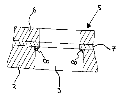
2 S Figure 3 is a cross section of portion of the screen plate with abrasion
resistant
plates welded thereon,

CA 02524540 2005-10-26
3
Figure 4 is a plan view of portion of the screen plate with the abrasion
resistant
plates in position,
Figure 5a, b, c. d. e. f. g. h. i show various shaped abrasion resistant
plates,
Figure 6 shows a preferred screen plate with square holes surrounded by
abrasion
n3sistant plates,
Fgure 7 is a cross-sectional view of the screen plate,
Figure 8 shows an example of one of the abrasion resistant plates, and
Figure 9 shows an example of a larger abrasion resistant plafie grooved to
facilitate
deliberate breaking into one or more smaller abrasion resistant plates,
DESCRIPTION OF THE PREFERRED EMBODIMENT
Referring t4 Figures I to 5 of the drawings the screen plate 1 comprises a
carrier
plate 2 having a plurality of screening holes 3 there through. In the example
the
screen plate is one of a plurality of curved screen plates to form a drum
through
which the material to be screened passes. Figure 1 shows a developed plan of a
1 S carrier plate while Figure 2 shows a typical Gross section of a curved
carrier plate.
The carrier plate 2 has a plurality of bolt holes 4 whereby the screen plate
can be
bolted to the structure supporting the Screen plate, in this case to the drum
sb~u~ure. 'me area extending diagonally across the babe with no screening
holes is due tv the substructure in the screen drum. Depending on the
structure of
the screen drum screening holes may cover the whole surface and also if the
screen plate is used as a flat sa een in other installations the holes may be
across
the whole plate, or have areas with no holes depending upon the supporting
shvcd~re.
To protect the surtaoe of the carrier plate abrasion resistant plates (ARP) 5
are
2 5 welded between the holes as shown in Flgure 4. As shown in the Figures
each of
the ARP are so shaped and dimensioned to overlap the edges of the holes in the
carrier plate, the holes teeing shown by dotted lines. The ARP 5 protect the
edges of the holes of the carrier plate.

CA 02524540 2005-10-26
4
Each of the ARP 5 comprise a highly abrasive resistant material 6 such as
white
iron brazed to a backing plate 7 of mild steel, examples of this material are
sold
under the registered trade marks DOMITE and L~4MINITE. These are welded to
the carrier plate by welding from underneath into the overlapping portion by a
S bead of weld 8 extending around the edge of the hole 3, as shown is Figure
3,
and the under surtace of the backing plate 7. Preferably the edge of the hole
3 is
chamfered or bevelled to provide a greater area for welding.
In the example shown the ARP may be produced in various shapes to cover the
spaces between the holes. The majority of these would be the shape A,
however around the edges the shapes can vary as illustrated in Figures 4 and
5.
Also it is noted some of the shapes such as C, D and E are produced in right
and
left hand v~rsions.
With the oonstructlon of this invention, if any of the ARP become
unserviceable for
any reason, the ARP can be removed by grinding out the weld, and welding in a
1 S new ARP. This results in less downtime than in the prior systems where the
entire
plate weighing over one tonne has to be removed and replaced.
A preferred version of the invention is shown in Fgures 6, 7 and 8. The
carrier
plate 10 has spaced square holes 11 flame cut therein. in this embodiment the
ARP are rectangular and are sized to overlap the adjacent holes 11 to protect
the
edges of the holes as in the previous embodiment. The edges of the holes are
bevelled or chamfered to receive the welding bead welding the ARP to the
Carrier
plate 10.
Referring now to Figure 9, there is shown a larger ARP In the form of four ARP
of A
shape separated by grooves 12. In this way one or more ARP can be separated
2 S from the others by deliberate fracturing along the groove or grooves 12.
Although
the A shape is illustrated it is realised the concept can be applied to other
shapes,
particularly the shape shown in Figures 6, 7 and 8.
The larger grooved ARP thus covers a greater area resulting in reduced
welding.
There are a reduced number of gaps between each ARP thereby decreasing the
exposure of preferential wear in the gap of each opening. Less items per
assembly are required and the cast in grooves provide the ability to mould
into the
curvature of the carrier plate.

CA 02524540 2005-10-26
While two embodiments of the Invention are described It is to be realised that
the
invention is not limited to these embodiments for the invention can be applied
to
quite a range of different applications where abrasive resistant screens are
required. Thus the hole sizes and shapes can vary, also th thickness of the
carrier
5 or base plate can vary depending upon the particular desired application of
use of
the screen plate. Also as described the invention can be applied ~ flat or
a,rrved
surfaces.
The ARP are welded to the base or carrier plate by welding the overlapping
portion to the bevelled edges of the holes in the base plate. Thus the size of
the
screen plate is determined by the spacing of the ARP, the size of the holes in
the
base plate being determined by the degree of overlap of the ARP over the
holes:
Thus each ARP is individually welds to the base or carrier plate and thus if
one or
more of the ARP are very severely damaged, they can be removed by grinding
out the weld and replaced. This then requires less down time compared with the
existing equipment where the whole panel has to be removed and replaced.
The ARP has definite advantages over the tungsten carbide plasma coating due
to the greater thickness of the white iron alloy a feature which ensures that
the
sidewalls of the screen openings are of the same wear resistant material as
the
surface, thus presenting a more durable edge to the screen openings than the
thin
layer of hard facing material which is known to spall away and expose the mild
steel
sub-strafe. During use the tungsten carbide plasma coating becomes damaged
particularly around the edge of the sd'een hole thus exposing the mild steel
carrier
plate which is thus exposed to abrasive attack. Also the ARP extend over the
edge of the hole in the carrier plate and thus the mild steel carrier plate Is
protected
from abrasive attack.
Although various embodiment of the invention have been described, the
invention
is not to be limited thereto but can include variations and modifications
falling within
the spirit and scope of the invention.

Dessin représentatif
Une figure unique qui représente un dessin illustrant l'invention.
États administratifs

2024-08-01 : Dans le cadre de la transition vers les Brevets de nouvelle génération (BNG), la base de données sur les brevets canadiens (BDBC) contient désormais un Historique d'événement plus détaillé, qui reproduit le Journal des événements de notre nouvelle solution interne.

Veuillez noter que les événements débutant par « Inactive : » se réfèrent à des événements qui ne sont plus utilisés dans notre nouvelle solution interne.

Pour une meilleure compréhension de l'état de la demande ou brevet qui figure sur cette page, la rubrique Mise en garde , et les descriptions de Brevet , Historique d'événement , Taxes périodiques et Historique des paiements devraient être consultées.

Historique d'événement

Description Date
Requête visant le maintien en état reçue 2024-10-10
Paiement d'une taxe pour le maintien en état jugé conforme 2024-10-10
Requête pour le changement d'adresse ou de mode de correspondance reçue 2019-11-20
Représentant commun nommé 2019-10-30
Lettre envoyée 2016-11-22
Inactive : Transfert individuel 2016-11-15
Accordé par délivrance 2008-07-29
Inactive : Page couverture publiée 2008-07-28
Préoctroi 2008-04-28
Inactive : Taxe finale reçue 2008-04-28
Lettre envoyée 2008-01-14
Un avis d'acceptation est envoyé 2008-01-14
Inactive : CIB attribuée 2008-01-13
Inactive : CIB attribuée 2008-01-11
Inactive : Approuvée aux fins d'acceptation (AFA) 2007-11-22
Modification reçue - modification volontaire 2007-06-08
Inactive : Dem. de l'examinateur art.29 Règles 2007-01-12
Inactive : Dem. de l'examinateur par.30(2) Règles 2007-01-12
Lettre envoyée 2006-12-12
Inactive : Transfert individuel 2006-10-26
Demande de correction du demandeur reçue 2006-10-26
Demande publiée (accessible au public) 2006-05-01
Inactive : Page couverture publiée 2006-04-30
Inactive : CIB attribuée 2006-04-20
Inactive : CIB en 1re position 2006-04-20
Inactive : Certificat de dépôt - RE (Anglais) 2005-12-07
Exigences de dépôt - jugé conforme 2005-12-07
Demande reçue - nationale ordinaire 2005-12-05
Lettre envoyée 2005-12-05
Toutes les exigences pour l'examen - jugée conforme 2005-10-26
Exigences pour une requête d'examen - jugée conforme 2005-10-26

Historique d'abandonnement

Il n'y a pas d'historique d'abandonnement

Taxes périodiques

Le dernier paiement a été reçu le 2007-08-09

Avis : Si le paiement en totalité n'a pas été reçu au plus tard à la date indiquée, une taxe supplémentaire peut être imposée, soit une des taxes suivantes :

  • taxe de rétablissement ;
  • taxe pour paiement en souffrance ; ou
  • taxe additionnelle pour le renversement d'une péremption réputée.

Veuillez vous référer à la page web des taxes sur les brevets de l'OPIC pour voir tous les montants actuels des taxes.

Titulaires au dossier

Les titulaires actuels et antérieures au dossier sont affichés en ordre alphabétique.

Titulaires actuels au dossier
CQMS PTY LTD
Titulaires antérieures au dossier
JOSEPH FERENCZ
PHILIP KEMPE
STEPHEN KERR DAVIS
Les propriétaires antérieurs qui ne figurent pas dans la liste des « Propriétaires au dossier » apparaîtront dans d'autres documents au dossier.
Documents

Pour visionner les fichiers sélectionnés, entrer le code reCAPTCHA :


Pour visualiser une image, cliquer sur un lien dans la colonne description du document. Pour télécharger l'image (les images), cliquer l'une ou plusieurs cases à cocher dans la première colonne et ensuite cliquer sur le bouton "Télécharger sélection en format PDF (archive Zip)" ou le bouton "Télécharger sélection (en un fichier PDF fusionné)".

Liste des documents de brevet publiés et non publiés sur la BDBC .

Si vous avez des difficultés à accéder au contenu, veuillez communiquer avec le Centre de services à la clientèle au 1-866-997-1936, ou envoyer un courriel au Centre de service à la clientèle de l'OPIC.


Description du
Document 
Date
(aaaa-mm-jj) 
Nombre de pages   Taille de l'image (Ko) 
Abrégé 2005-10-26 1 10
Description 2005-10-26 5 232
Revendications 2005-10-26 1 41
Dessins 2005-10-26 9 100
Dessin représentatif 2006-04-05 1 6
Page couverture 2006-04-26 1 29
Revendications 2007-06-08 1 25
Dessin représentatif 2008-07-18 1 7
Page couverture 2008-07-18 1 31
Confirmation de soumission électronique 2024-10-10 3 78
Accusé de réception de la requête d'examen 2005-12-05 1 176
Certificat de dépôt (anglais) 2005-12-07 1 157
Demande de preuve ou de transfert manquant 2006-10-30 1 101
Courtoisie - Certificat d'enregistrement (document(s) connexe(s)) 2006-12-12 1 105
Rappel de taxe de maintien due 2007-06-27 1 112
Avis du commissaire - Demande jugée acceptable 2008-01-14 1 163
Courtoisie - Certificat d'enregistrement (document(s) connexe(s)) 2016-11-22 1 101
Correspondance 2005-12-07 1 27
Correspondance 2005-12-07 1 26
Correspondance 2006-10-26 3 97
Taxes 2007-08-09 1 28
Correspondance 2008-04-28 1 33
Taxes 2008-09-12 1 34
Taxes 2009-10-15 1 34