Note : Les descriptions sont présentées dans la langue officielle dans laquelle elles ont été soumises.
CA 02525022 2005-11-O1
PLAY SET WITH TOY VEHICLE TRACK AND CARRIAGE
Related Application
This application claims the benefit of U.S. Provisional Application No.
60/691,465
filed on June 16, 2005, which is incorporated herein by reference for all
purposes.
Background of the Disclosure
Toy vehicle tracks and accompanying toy vehicles are a source of entertainment
for children. Toy vehicle tracks having different features may increase the
enjoyment of
children using the tracks.
The toy vehicles used on a toy vehicle track may utilize any suitable type of
propulsion. For example, toy vehicles may allow the wheels on the toy vehicle
to spin
freely when pushed. Toy vehicles may also be propelled by an energy source,
such as by
using one or more batteries or other source of electric power, by using
magnetic forces,
by using mechanical forces such as provided by a spring, or by using an
inertial flywheel
motor that gains its rotational energy by spinning the wheels of the toy
vehicle. Toy
vehicles may maintain contact with a track in various ways. For example,
contact
between the vehicle and the track may be maintained by gravity, by utilizing
the speed of
the propelled toy vehicle, by using magnetic forces, and/or by securing the
toy vehicle to
the track mechanically.
Examples of toy vehicle tracks can be found in U.S. Patent Nos. 2,239,395,
3,126,670, 3,299,565, 3,665,636, 3,690,393, 3,797,164, 4,068,402, 4,087,935,
4,091,995,
4,106,695, 4,185,409, 4,221,076, 4,254,576, 4,459,438, 4,468,031, 4,519,789,
4,536,168, 4,661,080, 4,697,812, 4,979,926, 5,052,972, 5,452,893, 5,601,490,
5,678,489,
1
CA 02525022 2005-11-O1
5,865,661, 5,890,945, 5,931,714, 6,093,079, 6,193,581, 6,478,654, 6,508,179,
6,676,480, RE32,106 and U.S. Application Publication No. 2003/0224697.
Different
types of toy vehicles suitable for use on toy vehicle tracks can be found in
U.S. Patent
Nos. 4,087,935, 4,241,534, 4,333,261, 4,536,169, 4,940,444, 6,422,151, and
6,764,376. All of the aforementioned patents are incorporated herein by
reference for all
purposes.
Summary of the Disclosure
In some examples, a toy vehicle play set may include a track assembly having a
first vehicle-support surface defining a travel path, and a carnage mounted
for travel
along the travel path and having a second vehicle-support surface. The first
and second
vehicle-support surfaces may be configured to support, in combination, a toy
vehicle.
In some examples, a toy vehicle play set may include a track having an end.
The track
may be configured to support a toy vehicle having at least a wheel on each
side of a
vehicle body. A rail may be supported relative to and extending from the end
of the
track. A carriage may be mounted for travel along the rail and have a vehicle-
support
surface. The carriage may be adapted to support at least partially a toy
vehicle and be
movable along the rail between a position near the end of the track and a
position spaced
from the end of the track.
In some examples, a method of propelling a toy vehicle along a track may
include
supporting the toy vehicle on a carnage with at least a first driven wheel of
the vehicle
supported on the track, driving the driven wheel of the supported toy vehicle,
and guiding
the carnage supporting the toy vehicle along the track.
2
CA 02525022 2005-11-O1
Brief Description of the Drawings
Fig. 1 is a perspective view of a play set including a toy vehicle supported
on a
track assembly.
Fig. 2 is a perspective view of an inclined toy-vehicle play set including the
track
assembly of Fig. 1.
Fig. 3 is a top view of a track transition at the lower end of the track
assembly of
Fig. 1.
Fig. 4 is a side perspective view of the transition shown in Fig. 2.
Fig. 5 is a front view of the vehicle supported on the track assembly of Fig.
1.
Fig. 6 is a cross-section taken along line 6-6 in Fig. 5.
Fig. 7 is a cross-section taken along line 7-7 in Fig. 6.
Fig. 8 is simplified side view of a toy vehicle in the track transition of
Fig. 3.
Fig. 9 is a simplified side view of the toy vehicle on the track assembly of
Fig. 1.
Fig. 10 is a simplified side view of the toy vehicle on a track transition at
the top
of the track set of Fig. 2.
Detailed Description
A toy vehicle play set may include a track adapted for use with a toy vehicle.
For
example, a toy vehicle play set may include an elongate track assembly having
a first
vehicle-support surface defining a travel path, and a carriage mounted for
travel along the
travel path and having a second vehicle-support surface. The first and second
vehicle-
support surfaces may be configured to support, in combination, a toy vehicle.
3
CA 02525022 2005-11-O1
In other examples, a toy vehicle play set may include a track having an end
and
configured to support a toy vehicle having at least a wheel on each side of a
vehicle body.
A rail may be supported relative to and extending from the end of the track. A
carriage
may be mounted for travel along the rail and may have a vehicle-support
surface. The
carnage may be movable along the rail between a position near the end of the
track and a
position spaced from the end of the track.
Also, in some examples, a method of propelling a toy vehicle along a track may
include supporting the toy vehicle on a carnage with at least a first driven
wheel of the
vehicle supported on a track, driving the driven wheel of the supported toy
vehicle, and
guiding the carnage supporting the toy vehicle along the track.
Also, in some examples, the toy vehicle may be unmotorized or may be
motorized,
and may have a single speed or a plurality of speeds. The track may be formed
with
plastic, although other suitable materials, such as metal, may also be used.
Furthermore,
sections of the track may be molded, although they may also be formed in
various other
ways as well, such as by cutting or pressing. The track may be comprised of
multiple
sections that may need to be assembled by the user before using the track. The
track may
be assembled by various connectors, including any sort of snap fit structure,
registration
pins, retaining clips, flanges, or any other integral or non-integral
structure capable of
attaching two or more sections of the track together.
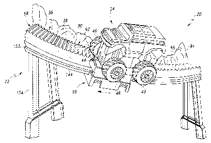
Figs. 1 and 2 depict a perspective view of one example of a toy vehicle play
set
shown generally at 20. Play set 20 may include a track set 22 and one or more
toy
vehicles, such as toy vehicle 24. 'Track set 22 may include track assemblies
26 having
4
CA 02525022 2005-11-O1
one or more tracks 28 serially positioned to define one or more travel paths,
such as a
continuous travel path 30 for a toy vehicle 24. In this example, there is a
first track
assembly 32 having a track 34, a second track assembly 36 having a track 38,
and a third
track assembly 40 having a track 42.
Fig. 1 depicts a perspective view of the toy vehicle 24, and Fig. 5 depicts a
front
view of toy vehicle 24. Toy vehicle 24 may include a body 44 supported by a
plurality of
wheels 46, 47, 48, 49. As used herein, a wheel is considered the rotating
structure on
which the vehicle is supported, and includes what may be considered to be the
tire, if any,
as well as the rim on which a tire may be mounted. Each wheel may rotate about
an axis
of rotation. In this example, wheels 46 and 48 rotate about a common wheel
axis 50.
Wheels 47 and 49 may also rotate about a similar common wheel axis.
Furthermore, the toy vehicle 24 may include one or more magnets in or on the
underside of body 44. The illustrated toy vehicle has two permanent magnets
51, 52, as
shown in Figs. 5, 7 and 9. The magnet or magnets may each or in combination be
any
source of a magnetic field. Thus, other forms of magnets may also be used,
such as
electromagnets. Magnet 51 may be aligned between wheels 46 and 47, while
magnet 52
may be aligned between wheels 48 and 49. The magnets 51, 52 may be positioned
on the
vehicle so that when the vehicle is on a track, the magnets are elevated a
sufficient
distance above the track to avoid making direct contact with the track. As
will be
described, the magnets 51, 52 may be positioned sufficiently low to provide a
strong
magnetic force of attraction with a moveable or stationary track element
having a
magnetic or ferromagnetic material.
5
CA 02525022 2005-11-O1
As indicated generally in Fig. 5, toy vehicle 24 may also include an
appropriate
drive mechanism 53 to facilitate imparting rotational power to one or more of
the toy
vehicle wheels 46, 47, 48, 49 to drive it along the track in a way described
below. Toy
vehicle drive mechanisms are well known. Wheels 46 and 47 are on the right
side of the
vehicle and opposite respective wheels 48 and 49 on the left side of the
vehicle. The toy
vehicle 24 may be an inertial-motor-powered toy vehicle, such as a toy vehicle
sold by
Mattel, Inc. under the trademark "Rev Ups.TM" Other toy vehicles with or
without drive
systems may also be used, such as ones with drive systems that are wind-up,
battery
powered, electric powered or powered by any other drive mechanism.
Fig. 2 depicts track set 22 including track assemblies 32, 36 and 40. As also
shown in Fig. 3, track assembly 32 may include track 34 having a generally
flat
vehicle-support surface 54 with a center strip 56 having a ferromagnetic metal
strip 58
extending along the length of the track. This strip 58 may be continuous or
discontinuous, and may be enclosed within a channel extending through the
track 34,
or it may be exposed. The complementary magnetic attraction between strip 58
and
vehicle magnets 51, 52 contribute to maintaining the vehicle on the track
during travel.
Optionally, strip 58 may be formed of magnetic material having a polarity
opposite to
that of magnets 51, 52, and magnets 51, 52 may be replaced with ferromagnetic
material. Accordingly, the magnets and the ferromagnetic strip may be referred
to
generally as magnetic attraction elements 59. Wheel lanes 60 and 62 are
disposed on
opposite sides of the center strip and are sized to align with respective sets
of vehicle
wheels 46, 47 and 48, 49 on opposite sides of the toy vehicle.
6
CA 02525022 2005-11-O1
The track assembly 32 may include raised edges 64, 66 on both sides of track
19, which may function as barriers to keep the toy vehicle 24 from falling off
of the
track. These track edges may guide the toy vehicle wheels 46-49 along vehicle-
support surface 54. Track 34 may be inclined, as shown, to form a ramp 68. One
end
70 of the track may be positioned on or near a play surface, or be connected
to or an
extension of a previous track assembly. The other track end 72 may be
supported in an
elevated position by a support structure 74.
In a track-transition region 76, travel path 30 transitions from track 34 to
track
38, as particularly shown in Figs. 2-4. In this transition region, opposing
guardrails 78,
80, provide moderate narrowing of track 34, generally consistent with track
edges 64,
66 to align a toy vehicle 24 with track 3 8 of track assembly 36. A distance D
1
between guardrails 78, 80 may be slightly more than a distance D2
corresponding to a
width of toy vehicle 24, as shown in Fig. 5.
Figs. 3-7 depict the track assembly 36, referred to as the cliffhanger section
36.
The cliff hanger section 36 may include an inclined track 38 that extends
between the
track assembly 32 on a lower end 70, and track assembly 40 on another, higher
end 72.
Tracks 34, 38 and 40 may be connected in varying ways, and may utilize any
sort of
snap fit structure, registration pins, retaining clips, flanges, or any other
suitable structure
adapted to attach two or more sections of the track to each other. In the
illustrated track
assembly, these and other connections are made by a snap-fit tab structure.
The track 38 may be sufficiently narrow to support only the wheels on one side
of the toy vehicle 24. In the illustrated track assembly, only the right side
wheels 46,
7
CA 02525022 2005-11-O1
47 of the toy vehicle 24 may be in contact with and supported on track 38 when
the toy
vehicle is traveling along the travel path 30. Track 38 thus may include a
vehicle-
support surface 86 that forms a single wheel lane 88. At track lower end 70,
wheel
lane 88 is aligned with wheel lane 60 of track 34. Vehicle-support surface 88
may
have a width D3, shown in Fig. 5, that is wider than a width D4 of a vehicle
wheel.
Optionally, support surface 86 may have a width that is wider or narrower than
the
width D2 of a vehicle. Since, in this example, only wheels on one side of the
toy
vehicle contact support surface 86, the width of this support surface may be
less than
the width D2 of a toy vehicle, and may even be less than the width D4 of a
vehicle
wheel.
The track 38 may further include a vehicle-support surface 86 that includes a
surface structure 90, which may provide increased traction between the track
surface
86 and the wheels 46, 47 of the toy vehicle 24 as the toy vehicle progresses
along the
track. In the illustrated embodiment, surface structure 90 may be in the form
of
laterally extending ridges 92. Other suitable surface textures, materials or
structures
may also be used.
The clifflianger section 36 may also include a wall, barrier or guardrail 94,
similar in this example to guardrail 78. The guardrail 94 may be placed along
the far
right side of the track (along the inside of the curve of the track, as shown)
and may
resemble a rock wall or other man-made or natural structure. Further,
guardrail 94
may be aligned with guardrail 78 and appear as a continuous guardrail 96
formed by
individual guardrails 78 and 94.
8
CA 02525022 2005-11-O1
The cliffhanger section 36 may also include a slide member or carriage 98, as
depicted in each of the figures. The clifflianger section may be configured to
support
the carriage for movement along travel path 30, such as along the track 38.
The
carriage 98 may be supported on a side of track 38, such as on the left side
as viewed
in Fig. 2.
As shown, the carriage 98 may include a carnage frame or body 100 having a
platform 102 with a vehicle-support surface 104, contact bearing wheels 106,
including in
this example, vertical-support bearing wheels 108, lateral-support bearing
wheel 110,
primary weight bearing wheels shown as rollers 112, and a carriage magnet or
ferromagnetic strip 114.
Carriage 98 may be adapted to support all or part of a toy vehicle 24. In the
example shown, vehicle-supporting surface 104 has a size appropriate to
support a
portion of the toy-vehicle body 44 between wheels 46, 47, 48, 49. In
particular, surface
104 has a length corresponding to the length of the vehicle body, and a width
DS that is
about the same, or slightly less than a distance D6 between opposing pairs of
wheels 46,
48 and/or wheels 47, 49.
Two rollers 112 spaced apart longitudinally along path 30 are supported on the
underside of platform 102. Rollers 112 have laterally extending axes of
rotation 118,
120. Carriage body 100 further includes a base portion 122 spaced below
platform 102
by a connecting neck 124 extending down from the side of platform 102 distal
of track
38, referred to as the distal side. Base portion 122 extends beyond the
proximal edge of
the platform (the edge adjacent to track 38) and under track 38. Three bracing
arms 126,
9
CA 02525022 2005-11-O1
I28, 130 extend upwardly from the base portion toward the under side of track
38. End
arms 126 and 128 terminate with vertical bearing wheels 108. These vertical
bearing
wheels rotate about horizontal, laterally extending axes 132, 134,
respectively, which
axes are parallel to axes 118, 120 of rollers 112. Intermediate bracing arm
130 terminates
with lateral-support bearing wheel 110, which wheel rotates about a vertical
axis I36.
The space between wheels 108, 110, platform 102 and base portion 122 forms a
generally
L-shaped channel 138 when viewed from an end of the carnage, as shown in Fig.
5.
Platform 102 further includes an upwardly extending rim 140 extending above
support surface 104. Rim 140 may extend above all or a portion of the support
surface.
In this example, rim 140 extends along the forward edge of the support
surface, as well as
along a portion of the sides of the support surface. The height of the rim may
be uniform
or it may vary. For example, the rim may have an elevated portion 142 along
the forward
edge, as shown in Fig. 5. Further, it may decrease in height with increasing
distance
along the sides of the support surface from the forward edge, as shown
particularly in
I 5 Fig. 7.
Also, as shown in Fig. 7, ferromagnetic strip 114 may be embedded in platform
102 just below support surface 104, and extend along the length of the support
surface.
Strip 114 may be a magnetic attraction element 59 made of a magnetic or
ferromagnetic
material that provides a magnetically complementary attraction to the magnetic
attraction
elements) on the toy vehicle.
Track 38 may be formed in, on or adjacent to a support assembly 116. In this
example, track 38 is formed as a part of support assembly I16. Support
assembly I16
CA 02525022 2005-11-O1
includes guardrail 94 extending from the edge of the track opposite from
carnage 98.
The support assembly also includes a carnage-supporting outrigger or frame 144
that
may function generally as a guide 145 for guiding the carriage 98 along travel
path 30
and track 38. Frame 144 has an L-shape, when viewed from a lateral cross
section of the
support assembly, as shown in Fig. 5. The L-shape of frame 144 is
complementary to
channel 138 in the carriage, with the two being sized to allow carriage 98 to
move freely
along frame 144. Frame 144 includes a generally vertical wall 146 supporting a
generally horizontal ledge 148 that terminates in a curved lip, ridge or rail
150 on which
carriage rollers 112 rest. Rail 150 may extend along the length of track 38
and may be
t 0 uniformly spaced from the track in alignment with the carriage rollers.
Rail 150, then,
may function as a carriage support element 151, and frame 144 may generally
function as
a guide.
It is seen that, when the carriage is in position with rollers 112 on rail
150, vertical
wheels 108 contact the underside of track 78, and lateral wheel 110 contacts
the backside
of wall 146 of the carriage-supporting frame. The axes of rotation for the
rollers 112 and
the vertical wheels 108 may also be parallel with the plane of the top surface
104 of the
platform 102. In use, platform surface 104 may be generally parallel to and/or
aligned
with the adjacent surface 86 of track 38. The combination of contact bearing
wheels 106,
that is wheels 108, 110, and rollers 112, hold the carnage 98 in place
relative to track 78.
Furthermore, the top surface of the rail 150 may also provide a bearing
surface on which
the top bearing rollers 112 may roll. With this configuration, the only
contacts between
the carriage 98 and the support assembly 116 are by wheels 106, which wheels
facilitate
11
CA 02525022 2005-11-O1
movement of carriage 98 along support assembly 116. Optionally, wheels 106 may
be on
support assembly 116, on both of support assembly 116 and carriage 98, or on
neither.
More or fewer wheels may be used, or other or no friction-reducing devices or
mechanisms may be used.
As shown generally in Fig. 2 and in further detail in Fig. 10, upper end 72 of
track
38 may be connected to track 42 of track assembly 40 in a track-transition
region 152.
The tracks 3 8 and 42 may be supported in an elevated position, as shown, or
in other
positions, by suitable support structures, such as support structures 154 and
156.
Similar to track 34, track 42 may include a generally flat vehicle-support
surface 158
with a center ferromagnetic metal strip 160 extending along the length of the
track to
facilitate maintaining the vehicle on the track during travel. Wheel lanes 162
and 164
are disposed on opposite sides of the center strip and are sized to align with
respective
sets of vehicle wheels 46, 47 and 48, 49 on opposite sides of the toy vehicle.
In track-transition region 152, travel path 30 transitions from track 38 to
track
42, as particularly shown in Fig. 10. In this transition region, opposing
guardrails 166,
168 ensure that a vehicle traveling along track 38 will be aligned with track
42. Track
assembly 36 is structured to cause support surface 104 of carriage 98 to drop
slightly
below the level of surface 86 of track 38 as the carriage 98 reaches upper
track end 72.
Distance D7 shown in Fig. 10 represents this drop in relative position of
surface 104.
Lane 162 of track 42 forms a continuation of lane 88 of track 38. However,
there is no
corresponding lane on track 38 for left wheels 49, 50 of the toy vehicle.
There is a
recess 170 in track 42 between the ends of lanes 162 and 164 and sized to
12
CA 02525022 2005-11-O1
accommodate platform 102 of the carriage. Thus, when the carriage is disposed
in
recess 170, as shown in Fig. 10, there is a portion of lane 164 along at least
a portion of
the Ieft side of the platform, in addition to the continuous lane along the
right side of
the platform.
Figs. 8, 9 and 10 collectively illustrate an exemplary use and operation of
play set
20. When toy vehicle 24 travels up track 34 along travel path 30, the vehicle
reaches
lower track transition 76. Because track 38 is inclined upwardly, after the
toy vehicle has
driven off of the carriage 98, the carriage slides down to the lowest position
at the lower
end 70 of the track, against a stop element 172 formed in the lower end of
track assembly
36, as shown in Figs 2-4 and 8. As shown in Fig. 8, vehicle 24 travels off of
the end of
track 34 and onto track 38. Right wheels 46, 47 continue along on lane 88.
However,
without a corresponding lane on the right side of the vehicle, the vehicle
drops down on
the left side until vehicle body 44 contacts platform surface 104. Platform
rim 140 may
prevent the vehicle from traveling beyond the front edge of the platform. The
vehicle
body comes to rest on the platform, with the left wheels hanging freely to the
side of the
platform, and the right wheels in contact with track surface 86. In this
position, magnets
51, 52 on the vehicle axe magnetically attracted to or drawn toward metal
strip 58 in
carriage 98, attracting and attaching the carriage to the vehicle.
With the toy vehicle 24 attached to and supported by the carriage 98, wheels
46,
47 are in driving contact with track surface 86, and wheels 48, 49 are not in
contact with
any surface. The drive mechanism of the toy vehicle may propel both the toy
vehicle and
the carriage along the cliffhanger section (track assembly) 36, as shown in
Fig. 9. Again,
13
CA 02525022 2005-11-O1
the bearing rollers 112 and bearing wheels 108, l I0 of the carriage and the
traction
provided by the ridges 92 of the track facilitate this travel.
The transition of toy vehicle 24 from track assembly 36 to track assembly 40
is
illustrated in Fig. 10. As the vehicle and carriage approach transition region
152, the
front of the carnage platform 102 enters recess 170, while also lowering in
relative
position to track surface 86, as is indicated by distance D7. When front left
wheel 49 of
the toy vehicle comes in contact with left wheel lane 164 of track surface
158, the wheel
raises up, lifting the left side of the toy vehicle. With the combination of
the lowering of
the platform and associated vehicle support surface 104 along and the raising
of the left
side of the vehicle, the vehicle body 44 lifts away from platform 102,
reducing the
magnetic attraction between the vehicle magnets and metal strip 114 in the
platform,
thereby allowing the vehicle to travel off of track 38 and onto track 42.
Because in this example, track assembly 36 is inclined upwardly, after the
vehicle
leaves carnage 98, the carriage slides back down along carriage-support frame
144 to
track assembly 32. The carriage thus returns to the lower, initial position
shown in Figs.
2-4, where the carriage is ready to receive another toy vehicle traveling up
ramp 68.
It is thus seen that, in some examples, a toy vehicle play set may include a
toy
vehicle including a body having first and second opposite sides and a bottom,
a plurality
of wheels at least partially supporting the body including a first wheel on
the first side of
the body and a second wheel spaced from the first wheel, a drive mechanism
configured
to drive at least a first wheel, and at least a first magnetic-attraction
element disposed in
the bottom of the vehicle body; a track defining a travel path; a carriage
adapted to
14
CA 02525022 2005-11-O1
support at least a portion of the toy vehicle and having at least a second
magnetic-
attraction element complementary with the at least first magnetic-attraction
element to
provide magnetic attraction between the first and second magnetic-attraction
elements,
and thereby physical attraction between the carnage and the toy vehicle; and a
guide
extending along at least a portion of the track and adapted to support the
carriage for
movement of the carriage along the path; the toy vehicle being adapted to be
positioned
on the carriage with the first wheel in contact with the track, with the drive
mechanism
moving the toy vehicle and carriage along the path when the toy vehicle is at
least
partially supported on the carnage with the first wheel in driving contact
with the track
and the first and second magnetic-attraction elements in magnetic attraction.
Several aspects of this exemplary method of game play may be modified from
that
disclosed above. Play may thus be configured to provide a game with a desired
degree of
complexity or difficulty, for example to adapt the game to players of a
predetermined age
range.
It is believed that the disclosure set forth above encompasses multiple
distinct
inventions with independent utility. While an example of each of these
inventions has
been disclosed in a preferred form, the specific examples thereof as disclosed
and
illustrated herein are not to be considered in a limiting sense as numerous
variations are
possible. The subject matter of the disclosures includes all novel and non-
obvious
combinations and subcombinations of the various elements, features, functions
and/or
properties disclosed herein. Similarly, where "a" or "a first" element or the
equivalent
CA 02525022 2005-11-O1
thereof is recited, such usage should be understood to include incorporation
of one or
more such elements, neither requiring nor excluding two or more such elements.
Inventions embodied in various combinations and subcombinations of features,
functions, elements, and/or properties may be claimed through presentation of
claims in a
related application. Such claims, whether they are directed to different
inventions or
directed to the same invention, whether different, broader, narrower or equal
in scope to
the other claims, are also regarded as included within the subject matter of
the present
disclosure.
16