Note : Les descriptions sont présentées dans la langue officielle dans laquelle elles ont été soumises.
CA 02526729 2005-11-23
Afoys WOBBEN
Argestrasse 19, 26607 Aurich
Rotor blade connection
The present invention concerns a rotor blade for a wind power
installation comprising a plurality of holes which are arranged in the region
of the rotor blade root and which are in the form of through holes which
extend substantially transversely with respect to the longitudinal axis of the
rotor blade, transverse pins which are fitted into the holes and tension
elements which can be connected to the transverse pins.
DE 197 33 372 C1 discloses a rotor blade with holes which are
arranged in the region of the rotor blade root and which extend
substantially transversely with respect to the longitudinal axis of the rotor
blade, transverse pins which are fitted into the holes and tension elements
which can be connected to the transverse pins. Those holes are in the form
of blind holes.
The book 'Windkraftanlagen' by Erich Hau, 2nd edition, Springer-
Verlag, 1996, page 202, which is deemed to be the most relevant state of
the art, discloses a rotor blade of the kind set forth in the opening part of
this specification. In that known rotor blade a tension element (referred to
therein as a tension anchor) extends from the transverse pin to a flange. In
that way the rotor blade can be fixed to the flange, for example of the rotor
hub.
The state of the art discloses tension elements extending within the
rotor blade root. Accordingly, passages have to be present in the material
of the rotor blade root, into which the tension elements are fitted. In
consideration of the material weakening that this entails, the material in
the region of the rotor blade root has to be reinforced by suitable structural
measures so as to ensure the required strength.
In order to eliminate those disadvantages by means of a structural
simplification, the rotor blade according to the invention is characterised by
tension elements extending outside the rotor blade root.
CA 02526729 2005-11-23
2
In that respect the invention is based on the realisation that in that
way the region of the rotor blade root at the hub is admittedly altered in an
aerodynamically disadvantageous fashion, but that does not have any
detrimental influence on the acoustic characteristics and the other
properties of the installation because that region of the rotor blade is
either
covered by the spinner or is disposed at least in the part of the rotor, which
rotates most slowly.
The rotor blade according to the invention involves the advantage
that on the one hand the material of the rotor blade in the region of the
rotor blade root is not weakened by passages and that the tension
elements can be subjected to visual checking at any time without
dismantling being required for that purpose. Accordingly for example
incipient corrosion can be immediately detected and eliminated.
In addition, replacement of a tension element is easily possible.
Particularly when using fibre-reinforced epoxy resin composite
material as a sight and at the same time robust material for rotor blades, it
is possible to provide for durable anchoring of the transverse pins in the
rotor blade root. In that respect the arrangement affords an advantageous
transmission of force from a transverse pin into the epoxy resin composite
material of the rotor blade.
Desirably there are provided a plurality of spaced holes for receiving
a plurality of transverse pins in the rotor blade as in that way the strength
of the rotor blade connection can be substantially increased, which is
necessary in particular in the case of very large wind power installations.
The holes can be so spaced that the material is only insignificantly
weakened by the holes.
A particularly preferred embodiment of the invention is one in which
the rotor blade is of an enlarged cross-section in the region of the rotor
blade root and the hole or the holes is/are arranged in the region of that
enlarged cross-section. That measure can also substantially increase the
load-bearing capability of the connection between the rotor blade and the
rotor hub as the rotor blade is subjected to substantially lower levels of
stress due to the cross-sectional enlargement in the region of the rotor
CA 02526729 2005-11-23
3
blade root and can thus be acted upon by higher forces. The arrangement
according to the invention of the holes in the region of the enlarged cross-
section permits an advantageous transmission of force from the transverse
pin to the material of the rotor blade by way of a correspondingly enlarged
surface area white a substantially lower pressure in relation to surface area
occurs at the interface between the transverse pin and the inside surface of
the opening. In that case the cross-sectional enlargement can be of a
markedly smaller extent than in the case of a known rotor blade as there is
no need to compensate for the bores for tension elements which extend
within the rotor blade.
In accordance with a particularly preferred embodiment of the
invention the cross-section of the rotor blade enlarges on both sides in the
direction of an end portion, towards the hub, of the rotor blade. That
provides for a symmetrical transmission of force from the transverse pins
~5 to the rotor blade.
In accordance with a preferred development of this embodiment the
rotor blade has two oppositely disposed thickening portions which are
respectively formed in one piece with the rotor blade and the holes are
arranged at least partly in the region of the thickening portions. The
thickening portions which contribute to the cross-sectional enlargement can
be formed in a simple known manner by lamination on to the rotor blade of
a plurality of layers of fibre composite material and epoxy resin.
In addition a particularly preferred embodiment is one in which the
rotor blade in the region of the rotor blade root has a substantially tubular
end portion in which a plurality of holes are provided. A tubular end portion
can be fixed to the rotor hub in a particularly uniform and simple manner
and is advantageous in particular in the case of very large wind power
installations in respect of which extreme forces occur and the rotor blades
of which involve a transition from the tubular end portion for fixing
purposes to a wing profile portion.
An embodiment in which the rotor blade substantially comprises a
glass fibre-reinforced epoxy resin composite material provides that the
material is of great lightness, combined with a high level of strength.
CA 02526729 2005-11-23
In order to provide for better load transmission the transverse pins
are preferably glued into the hole. In addition there is the advantage that
the transverse pins can be reliably held in the predetermined position,
including while the tension elements are installed.
In a particularly preferred feature metal discs can be provided
concentrically around the longitudinal axis of the hole (or the transverse
pin) at at least one but preferably both ends of the hole. Those discs which
in shape are comparable to known support washers are fitted flush with the
surface of the rotor blade root in the region of the hole and prevent
damage to the edge of the hole.
In a further preferred embodiment a sleeve is fitted into or glued into
the hole. That sleeve is of a metallic material and prevents friction from
occurring between the wall of the hole and the transverse pin. Any friction
which occurs takes place between the transverse pin and the sleeve.
The above-discussed advantages of a rotor blade according to the
invention are enjoyed in a similar manner in a rotor for a wind power
installation of the kind set forth in the opening part of this specification,
which rotor is equipped with a rotor blade according to the invention. For
the avoidance of repetition therefore reference is directed to the foregoing
description in respect of the advantageous effects.
A preferred development of the rotor according to the invention is
distinguished in that the rotor hub has a peripherally extending flange
portion of substantially T-shaped cross-section for connection of the rotor
blade and the rotor blade is screwed to the flange portion by means of a
plurality of tension elements which are connected to transverse pins fitted
to the rotor blade. The desirably symmetrical T-shaped flange portion can
provide for the symmetrical transmission of forces from the rotor blade to
the hub, insofar as through bores are provided in both free portions, which
are disposed substantially in one plane, of the T-shaped flange portion, with
the tension elements, engaging through the through bores. Desirably the
plurality of tension elements are arranged in paired mutually parallel
relationship and substantially in two mutually concentrically disposed rows.
' , CA 02526729 2005-11-23
., 5
The advantages according to the invention are also embodied in a
wind power installation equipped with a rotor and/or a rotor blade of the
above-described kind; in regard to the advantages according to the
invention which can be attained thereby, reference is made to the foregoing
description in relation to a rotor blade and rotor according to the invention.
The invention is described hereinafter by means of an embodiment of
a rotor of a wind power installation with reference to the accompanying
drawings in which:
Figure 1 shows a simplified illustration of a wind power installation
according to the invention,
Figure 2 shows a sectional view of the fixing according to the
invention of a rotor blade to a rotor hub of a wind power installation,
Figure 3 shows a detail view from Figure 2, and
Figure 4 shows a sectional illustration of an alternative embodiment
of the invention.
The wind power installation 1 shown in Figure 1 substantially
includes a pylon 3 and a pod 5 fixed thereto, for receiving a generator 7
and a rotor 9 connected directly thereto. The rotor 9 has a rotor hub 11
and three rotor blades 2 fixed to the rotor hub 11. The rotor hub il is
caused to rotate by the wind forces acting on the rotor blade 2, to drive the
generator 7.
The generator 7 which is in the form of a ring generator has a stator
13 and a generator rotor 15. The generator rotor 15 is supported together
with the rotor hub li by means of main bearings 17 on a journal 19 fixedly
connected to a so-called machine carrier 21. The machine carrier 21 is
supported pivotably on the pylon 3 by means of a rotary mounting (not
shown); by means of azimuth motors 23. A device 27 with anemometer
and wind vane is also fixed to the machine carrier 21.
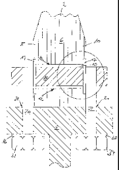
Figure 2 is a sectional view showing a portion, at the blade root end,
of a rotor blade 2 of a wind power installation 1 which can be for example a
so-called horizontal-axis wind power installation, as shown in Figure 1.
The rotor blade 2 which is partly shown in Figure 2 is of a lightweight
structure comprising a glass fibre-reinforced epoxy resin composite
' , ' , CA 02526729 2005-11-23
6
material and is fixedly connected to the rotor hub 11 by means of a rotor
blade connection 29 (Figure 1) according to the invention, insofar as the
rotor blade 2 is screwed to a peripherally extending flange 4 which is of T-
shaped cross-section and which in turn is provided integrally with the rotor
hub 11. The portion of the rotor blade 2 shown in Figure 1 - just like the
flange 4 - is of a peripherally extending and substantially tubular
configuration and, with an increasing distance from the rotor blade 11,
forms a transition into the aerodynamically active rotor blade profile (not
shown). A blade adaptor 31 can be arranged between the rotor blade
connection 29 and the rotor hub li. The rotor blade 2 together with the
blade connection 29 and the blade adaptor 31 can be turned about the
longitudinal axis of the rotor blade 2 by means of a blade adjusting motor.
Figure 2 shows the double-sided enlargement according to the
invention of the cross-section of the rotor blade 2 in the region of the rotor
blade root 6, that is to say, in the illustrated embodiment, the end region of
the substantially tubular portion of the rotor blade which in the assembled
condition bears against the flange 4 of the rotor hub il. Formed at
oppositely disposed lateral regions of the rotor blade root 6 are thickening
portions 8, 10 which provide for an enlargement in the cross-section of the
rotor blade 2 in a direction towards the end region of the rotor blade 2, in
the region of the rotor blade root 6. The enlarged cross-section provides a
high level of strength there. The thickening portions 8, 10 can be produced
integrally on the rotor blade root 6 for example by the application of
additional epoxy resin and fibre layers.
Through holes 12 are provided in the region of the rotor blade root 6,
distributed over the periphery of the rotor blade 6. Transverse pins 16 of
metal are fitted into those holes 12, as anchorage elements, within the
rotor blade 2.
The transverse pins 16 are of a length which goes beyond the
thickness of the rotor blade root 6 and through holes are provided in the
end regions thereof, outside the rotor blade root 6 and on both sides
thereof. The through holes can have for example female screwthreads (not
shown). They co-operate with tension elements 20, 22 in the form of
~
. , CA 02526729 2005-11-23
7
cylindrical bolts of metal. Those tension elements 20, 22 can be provided
with a male screwthread with which they are screwed into the
corresponding female screwthread of the transverse pin 16.
The tension elements 20, 22 extend outside the rotor blade 2 on
both sides of the rotor blade root through bores 28, 30 in the flange 4. The
tension elements 20, 22 can be subjected to high levels of tensile force by
means of a nut 32, 34 which can be screwed on to a (further) male
screwthread of the tension elements 20, 22, with the interposition of a
sleeve or a support washer 36, 38, and thus the rotor blade 2 can be pulled
firmly against the flange 4 and thus the rotor hub 11 so that a firm
connection is made between the rotor blade 2 and the rotor hub 11.
Figure 3 is a view on an enlarged scale of a portion from Figure 2. It
can be particularly clearly seen how the sleeve 15 is disposed in the hole
12, the transverse pin is disposed in the sleeve 15 and a disc 17 is
arranged around the transverse pin.
So that the tension elements 20, 22 extend as closely as possible to
the surface of the root region 6 of the rotor blade 2 the discs 17 are
arranged flush with the surface of the root region 6 of the rotor blade 2.
Just as the transverse pin 16 can be glued into the hole 12, the
sleeve 15 can also be glued into the hole. In that way it is possible to avoid
movements between the transverse pin 16 and the wall of the hole 12.
They occur instead of that between the sleeve 15 and the transverse pin
16. Even if those movements can be only extremely slight (so-called
micromovements) due to the transverse pin 16 being fixedly clamped by
the tension elements 20, 22, the continuous loading can nonetheless
otherwise give rise to damage.
Figure 4 shows an alternative simpler embodiment of the invention.
In this embodiment the transverse pin 16 extends alone within the hole 12
without a sleeve. It will be appreciated that the transverse pin 16 can again
be glued into the hole 12 in order to prevent movement between the two
components and thus to prevent abrasion of the material of the rotor blade
root 6 and at the same time to hold the transverse pin 16 in its
predetermined position during the assembly procedure.
CA 02526729 2005-11-23
8
The further structure corresponds to that of the known embodiment:
the tension elements 20, 22 extend through the flange and are fixed by
means of nuts 32, 34, with the interposition of discs 36, 38.
When implementing the rotor blades in wind power installations, it is
particularly advantageous if the wind power installation is such an
installation in which the rotor blade is carried by a rotor and the rotor
blades can be adjusted in respect of their angle to the wind by means of
pitch control. In that case it can also be particularly advantageous if the
pitch drive comprises not just one pitch drive but two or three pitch drives.