Note : Les descriptions sont présentées dans la langue officielle dans laquelle elles ont été soumises.
CA 02527453 2008-05-28
SYSTEM AND METHOD FOR CONSTRUCTION
OF LOG STRUCTURE
Technical Field
[0001] This invention relates to the manufacture and construction of
wooden log structures, and in particular to the manufacture and construction
of wooden log structures using logs of non-uniform shape.
Background
[0002] Conventional construction of a log structure involves scribing the
bottom of each log being placed successively above the log below to form a
rising wall in such a way that it fits closely with the log that it is to be
placed
above. Scribing is done using various guidelines, and usually involves
cutting the desired shape with a manually operated chainsaw. A disadvantage
of this method is that it requires "House Logs", which are expensive to
acquire because they must be very straight with limited taper, so that they
may be fitted together with a minimal amount of reshaping from the log home
builder operating the chainsaw. Such persons have generally trained as a log
builder under the guidance of a more experienced teacher with years of
experience. Consequently, they are very highly paid workers. This "Scribe
Method" for building log structures is still very slow, with only a few logs
being prepared each day. This inevitably results in an expensive log
structure.
[0003] Another method which is more automated involves milling sawn
timbers, so the resulting pieces fit tightly together in a vertical stacked
relationship. The sawn timbers are shaped to look like small logs. This
method is still quite expensive, and results in difficulties in supplying
electricity to the dwelling, or hiding plumbing from view. Further, the
insulating capacity of the relatively thin wooden walls is relatively low.
CA 02527453 2008-05-28
-2-
[0004] There is thus a need for a design of a log structure that is
suitable for use with logs of uneven shape, and which permits the
concealment of electrical or plumbing infrastructure while providing good
insulative capabilities.
[0005] The foregoing examples of the related art and limitations related
thereto are intended to be illustrative and not exclusive. Other limitations
of
the related art will become apparent to those of skill in the art upon a
reading
of the specification and a study of the drawings.
Summary
[0006] The following embodiments and aspects thereof are described
and illustrated in conjunction with systems, tools and methods which are
meant to be exemplary and illustrative, not limiting in scope. In various
embodiments, one or more of the above-described problems have been
reduced or eliminated, while other embodiments are directed to other
improvements.
[0007] A system for building a log structure is provided. A plurality of
logs are provided. Each log has one pair of parallel spaced apart
longitudinally extending grooves on one surface, and one pair of parallel
spaced-apart longitudinally extending grooves on a second surface of the log
opposite the first surface. A plurality of lumber support pieces are provided,
first edges of the lumber support pieces being dimensioned to engage the
grooves on the first surface of the logs, and second edges of the lumber
support pieces being dimensioned to engage the grooves on the second
surface of the logs. Inner edges of each groove may be tapered inwardly
from the outer surface of the log towards the base of the groove. The
CA 02527453 2008-05-28
-3-
grooves may be milled to a uniform shape, regardless of the exterior
dimensions of the log.
[0008] A method for building a log wall is provided. A base log having
two parallel spaced apart grooves on an upper edge of the base log is
provided, as are a plurality of lumber support pieces dimensioned to fit into
the grooves. Each lumber support piece has upper and lower edges and ends.
A plurality of logs are provided. Each log has a pair of parallel spaced-apart
longitudinally extending grooves on both an upper and a lower surface of the
log. A base log is positioned at the desired location of the log wall, and a
lower edge of each one of a first pair lumber support pieces is inserted into
one of the grooves on the upper edge of the base log. The grooves on a
lower surface of a first log are inserted onto upper edges of the first pair
of
lumber support pieces. Lower edges of each one of a second pair of lumber
support pieces are inserted into each of the grooves on the upper edge of the
first log. Successive layers of logs and lumber support pieces may be added
in like manner until the desired height of the log wall is achieved. The inner
edges of the grooves may be provided with an inward taper from the outside
of the log toward the base of the groove. The grooves may be milled to a
uniform shape, regardless of the exterior dimensions of the logs.
[0009] A method for building a log structure is provided. A plurality of
base logs having two parallel spaced apart grooves on an upper surface of the
base log are provided, as are a plurality of lumber support pieces
dimensioned to fit into the groove. Each lumber support piece has upper and
lower edges and ends. A plurality of logs, each log having a pair of parallel
spaced-apart longitudinally extending grooves on both an upper and a lower
surface of the log are provided, as are a plurality of corner posts. Each
corner post has two pairs of longitudinally extending parallel channels, the
channels being dimensioned to receive the ends of the lumber support pieces.
CA 02527453 2008-05-28
-4-
The base logs are positioned at the location of the walls of the log
structure,
and corner posts are positioned at the desired location of the corners of the
structure, so that the channels of the corner posts are aligned with the
grooves
on the base log. Each wall of the structure is constructed by inserting ends
of
a first pair of lumber support pieces into corresponding channels of adjacent
corner posts and inserting lower edges of each one of the first pair of the
lumber support pieces into one of the grooves on the upper surface of the
base log. Grooves on the lower surface of a first log are inserted onto upper
edges of the first pair of lumber support pieces. Ends of a second pair of
lumber support pieces are inserted into the corresponding channels of the
adjacent corner posts, and lower edges of each one of the second pair of
lumber support pieces are inserted into one of the grooves on the upper
surface of the first log. Successive layers of logs and lumber support pieces
are added in like manner until the desired height of the log structure on all
sides is achieved. An inner edge of the grooves may be provided with an
inward taper from the outside of the log toward the base of the groove.
Plumbing, electrical wiring or insulation may be provided in a space defined
between adjacent logs and a pair of lumber support pieces positioned
therebetween.
[00010] A log structure is provided. The log structure has at least one
base log with two parallel spaced apart grooves on an upper surface of the
base log. Lower edges of each one of a first pair of lumber support pieces
are fittingly engaged with one of the grooves on the base log. The log
structure has at least one log with a pair of parallel spaced apart
longitudinally extending grooves on an upper surface and on a lower surface
of the log, the grooves on the lower surface of the log being fittingly
engaged
with upper edges of the first pair of lumber support pieces. The log structure
has at least a second pair of lumber support pieces, lower edges of each one
of the second pair of lumber support pieces being fittingly engaged with one
CA 02527453 2008-05-28
-5-
of the grooves on the upper surface of the at least one log. The structure
may have further layers of logs and lumber support pieces joined in like
manner to provide a log wall of the desired height above each of the at least
one base logs.
[00011] The structure may have at least one corner post with two pairs of
longitudinally extending parallel channels dimensioned to receive ends of the
lumber support pieces. First ends of all of the lumber support pieces above a
first end of the at least one base log are engaged with the channels of the
corner post. Spaces defined between adjacent logs and a pair of lumber
support pieces may be used to run electrical wiring or plumbing, or may be
filled with insulation. An inner edge of each groove may taper inwardly
from the outer surface of the log towards the base of the groove. The
grooves may be milled to a uniform shape, regardless of the exterior
dimensions of the log.
[00012] A log wall including a plurality of logs, each log having at least
one groove on an upper surface of the log and at least one groove on a lower
surface of the log, and also including a plurality of lumber support pieces
having edges dimensioned to engage with the grooves on the logs, is also
provided. A first wall portion is formed by successive vertical layers of
lumber support pieces engaged with the grooves of the logs, and a second
wall portion is formed by successive vertical layers of lumber support pieces
engaged with the grooves of the logs. The second wall portion is formed in
close proximity to the first wall portion. The vertical elevations of the logs
in
the first wall portion may be staggered relative to the vertical elevations of
the logs in the second wall portion.
CA 02527453 2008-05-28
-6-
[00013] In addition to the exemplary aspects and embodiments described
above, further aspects and embodiments will become apparent by reference to
the drawings and by study of the following detailed descriptions.
Brief Description of Drawings
[00014] Exemplary embodiments are illustrated in referenced figures of
the drawings. It is intended that the embodiments and figures disclosed
herein are to be considered illustrative rather than restrictive.
[00015] Figure 1A is an end view of an embodiment of a portion of a log
wall 10 made in accordance with one aspect of the invention.
[00016] Figure 1 B is a perspective view of the FIG. 1A embodiment.
[00017] Figure 2 is an end view of an embodiment of a log 20 showing
grooves 24, 26 with inwardly tapered inner edges.
[00018] Figure 3 is a schematic drawing showing how grooves 24, 26
may be made in a curved log 21.
[00019] Figures 4A - 4C show different embodiments of a base log.
Figure 4A is an end view of a base log 36A that is the same as logs 20.
Figure 4B is an end view of a base log 36B wherein the lower surface of the
log is cut to provide a flat edge 38. Figure 4C is an end view of a base log
36C wherein the lower surface of the log has been cut to provide a flat edge
38 , which includes lower grooves 26' to receive lumber support pieces 22.
[00020] Figure 5 is a perspective view of an embodiment of a log wall 10
wherein electrical wiring is provided within space 40.
CA 02527453 2008-05-28
-7-
[00021] Figure 6 is an end view of an embodiment of a portion of a log
wall 12 made in accordance with another aspect of the invention.
[00022] Figure 7 is an end view of an embodiment of a log wall 16.
[00023] Figures 8A-8D show the construction of a corner 56 of a log
structure 14. Figure 8A shows the engagement of logs 20 with corner post
58. Figure 8B shows a possible placement of optional guide bolts 62 on logs
20. Figure 8C shows a corner portion 56 wherein ends 64 of lumber support
pieces and channels 60 of the corner post 58 have been half-dovetailed.
Figure 8D shows an embodiment of a corner 56 wherein the angle between
the walls of the log structure is 135 .
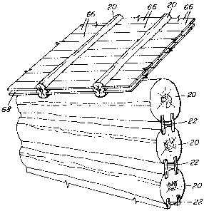
[00024] Figure 9 shows an embodiment of a roofing structure made from
logs 20 and roofing panels 66.
Description
[00025] Throughout the following description specific details are set forth
in order to provide a more thorough understanding to persons skilled in the
art. However, well known elements may not have been shown or described
in detail to avoid unnecessarily obscuring the disclosure. Accordingly, the
description and drawings are to be regarded in an illustrative, rather than a
restrictive, sense.
[00026] With reference to FIG. 1A, a log wall 10 may be formed from a
series of logs 20 and lumber support pieces 22. As best illustrated in FIG. 2,
a log 20 for use in the construction of wall 10 is provided with two pairs of
parallel grooves 24, 26 on opposing sides of the log, preferably by milling
CA 02527453 2009-02-17
-8-
the log. Grooves 24, 26 preferably extend longitudinally throughout the
length of log 20, and are milled to a uniform shape, regardless of the local
diameter of log 20, to receive lumber support pieces 22 of uniform
dimensions. The resulting distance between the top edge 25 and bottom edge
27 of lumber support pieces 22 is log gain 23. While log gain 23 may be the
same for all logs used, in order to maintain layers of logs 20 with a uniform
spacing, it is not necessary that log gain 23 be the same. Use of a varying
log gain 23 may be efficient, for example, where logs 20 of widely differing
diameters are to be used, to avoid wood waste by cutting excessively deep
channels 24, 26 in logs 20 of larger diameter. Accordingly, regardless of the
diameter of the logs used, or the variations in shape or taper of logs 20, log
wall 10 may be rapidly and readily constructed from such logs, because logs
may be prepared off-site and in large quantities.
15 [00027] An example of how grooves 24, 26 on a curved log 21 allow
curved log 21 to be used in the construction of log wall 10 is shown in FIG.
3. Because grooves 24 and 26 are milled to be of a uniform, preferably
straight shape (i.e. generally rectangular), regardless of variations in the
shape or taper of log 20 or curved log 21, grooves 24, 26 will be of proper
20 size and orientation to receive lumber support pieces 22. Accordingly, logs
20 or 21 may be prepared off-site and before construction of log wall 10,
without the need for a skilled craftsperson, thereby greatly reducing the time
and cost previously associated with the construction of a log structure.
[00028] Each of grooves 24, 26 has inner edges, shown respectively as
24A and 26A, and outer edges, shown respectively as 24B and 26B. Outer
edges 24B and 26B are vertical or nearly vertical when log 20 is in the
installed orientation. Inner edges 24A and 26A may be tapered slightly
inwardly from the outside edge of log 20 toward the base of grooves 24, 26.
Thus, the opening of grooves 24, 26 may be wider than the base of grooves
CA 02527453 2008-05-28
-9-
24, 26. In some embodiments, the angle 0 between the base of the groove 24
or 26 and the inner edge 24A or 26A is 93 . The tapered inner edges of
grooves 24, 26 force lumber support pieces 22 towards the outer edges 24B,
26B of grooves 24, 26. This design permits lumber support pieces 22 to be
more easily inserted into grooves 24, 26, and also results in log wall 10
becoming tighter as the weight of logs 20 presses down on lumber support
pieces 22. This design also has the advantage of permitting less water to leak
into the joint on the outside surface of log wall 20 than would be the case if
inner edges 24A and 24B were not tapered.
[00029] To form a log wall 10, a base log is provided. The base log may
be formed in the same manner as logs 20, as illustrated, for example, by base
log 36A in FIG. 4A. Lumber support pieces 22 may then be placed on the
ground, foundation, or other structure that is intended to support log wall
10,
and lower grooves 26 of base log 36A may receive lumber support pieces 22.
Alternatively, the base log may be cut to provide a flat edge 38. Flat edge 38
may itself contact the ground, foundation, or other structure that is intended
to support log wall 10, as illustrated by base log 36B in FIG. 4B. In that
case, it will be appreciated that log 36B may be provided without lower
grooves 26. Alternatively, flat edge 38' may include lower grooves 26' to
receive lumber support pieces 22, as illustrated for example by base log 36C
in FIG. 4C. In the embodiment of FIG. 4C, lumber support pieces 22
extending from lower grooves 26' would contact the ground, foundation, or
other structure intended to support log wall 10.
[00030] Log wall 10 may then be built upon base log 36A, 36B or 36C
by successively inserting lumber support pieces 22 into upper grooves 24 of
the base log, then positioning lower grooves 26 of a log 20 over the upper
edges of lumber support pieces 22. The weight of log 20, and of log wall 10
as the wall is constructed, will cause lumber support pieces 22 to be tightly
CA 02527453 2008-05-28
- 10-
inserted into grooves 24 and 26, thereby providing strength to log wall 10.
Log wall 10 may be built to the desired height by likewise continuing to
provide alternate layers of logs 20 and lumber support pieces 22.
[00031] A log wall 10 constructed as described above, i.e. wherein logs
20 have pairs of parallel grooves, provides an open space 40 (see Figures 1A
and 5) defined between two adjacent logs 20 and the two parallel lumber
support pieces 22 positioned therebetween. Open space 40 may be used to
provide a space to run electrical wiring throughout a log building structure,
as
shown in FIG. 5, or for plumbing in warmer climates. If it is desired to run
electrical wiring in open space 40, sealed wire runs 42 would be supported in
place as log wall 10 is being constructed, as shown in FIG. 5. Sealed wire
runs 42 could be hung out of pre-cut electrical box openings, so that sealed
wire runs 42 could be tied together and locked up after log wall 10 has been
erected. In this manner, electrical wiring may be directed to switch boxes or
electrical outlets 44 where desired within the structure.
[00032] Open spaces 40 may also be insulated to a higher R factor than
the wooden log itself by providing pre-cut holes (not shown) in those lumber
support pieces 22 which will be on the interior of the structure. An
expanding foam insulation, which may be for example IcyneneTM, may be
blown into spaces 40, and the pre-cut holes thereafter plugged to provide a
smooth interior wall surface.
[00033] In an alternative wall structure 12 shown in FIG. 6, each log 48
is provided with one single groove 50 on each of its opposing surfaces.
Grooves 50 are dimensioned to fittingly engage edges 25, 27 of lumber
support pieces 22. A log wall structure 12 may be constructed by forming a
first wall portion 52 comprising alternating layers of logs 48 and lumber
support pieces 22. An adjacent second wall portion 54 extending parallel to
CA 02527453 2008-05-28
-11-
first wall portion 52 and spaced a desired distance apart therefrom may
likewise be formed from alternating layers of logs 48 and lumber support
pieces 22 to form wall structure 12. Preferably the vertical elevation of logs
48 in the first and second wall portions 52, 54 is staggered, to permit first
and second wall portions 52, 54 to be positioned in close lateral proximity.
Additionally, smaller logs may be used to construct alternative wall structure
12 than would ordinarily be used to construct log wall 10, because only a
single groove 50 must be cut into log 48. With this construction, an open
space 55 is defined between first and second wall portions 52, 54. Open
space 55 may be used to run electrical wiring or plumbing pipe, or be filled
with expanding foam insulation, as described above with reference to space
40.
[00034] If it is not necessary or desired to define an open space 55
between the wall portions of wall structure 12, then a single wall portion 52
or 54 may be constructed as described above, to serve as log wall 16, shown
in FIG. 7. In the construction of log wall 16, logs of larger diameter and
lumber support pieces 22 of greater width may be used to provide a more
substantial wall 16.
[00035] With reference to FIG. 8A-8D, to construct a corner 56 of a log
structure 14, a timber log corner post 58 may be used. Timber log corner
post 58 may be, for example, one quarter of a rounded log. Timber log
corner post 58 includes a pair of longitudinally extending spaced apart
channels 60, which are vertically oriented when corner post 58 is in the
installed configuration. The space between channels 60 corresponds to the
space between grooves 24, and between grooves 26, on logs 20, so that
lumber support pieces 22 project into channels 60 when structure 14 is
assembled (see FIG. 8A). Steel guide bolts 62 may be affixed to logs 20 at
CA 02527453 2008-05-28
- 12-
each end of log 20, and secured in timber log corner post 58 in channels 60,
for example as shown in FIG. 8A and FIG. 8B.
[00036] With reference to FIG. 8C, the ends 64 of lumber support pieces
22 may also or alternatively be half-dovetailed to allow for shrinkage and
movement of structure 14, while preventing lumber support pieces 22 from
being pulled out from vertical channels 60. In embodiments where the ends
64 of lumber support pieces 22 are half-dovetailed, channels 60 will be
half-dovetailed in corresponding fashion to engage with the ends of lumber
support pieces 22. However, the ends 64 may be profiled with a slightly
smaller half-dovetail than channels 60, to allow for movement or shrinkage of
structure 14, while still preventing ends 64 from being pulled out from
vertical channels 60.
[00037] While in the illustrated embodiments a corner post 58 providing
an approximately 90 angle has been shown to describe the construction of
corner 56, it will be appreciated that corner 58 could be constructed to
define
other angles, depending on the desired shape of log structure 14. For
example, as illustrated in FIG. 8D, corner post 58 could be configured to
provide an angle of 135 between intersecting log walls if it was desired to
construct a log structure 14 having an octagonal shape.
[00038] To construct a log structure 14, an appropriate number of base
logs may be positioned at the desired location of log walls 10 of the
structure.
Corner posts 58 providing the desired angle of intersection of log walls 10
may then be positioned at the corners 56 of structure 14, so that channels 60
in corner posts 58 are aligned with grooves 24 of base log 36. Corner posts
58 may optionally be coupled to base logs 36, for example with steel guide
bolts 62 as described earlier. Lower edges of a first layer of lumber support
pieces 22 may then be slid vertically down channels 60 and inserted into
CA 02527453 2008-05-28
- 13 -
grooves 24. Provided that lumber support pieces 22 are longer than log 20,
their ends can extend into channels 60. Of course, the ends 64 of lumber
support pieces 22 should not extend past the ends of logs 20 by a length
longer than the depth of channels 60. A first layer of logs 20 may then be
built up by fitting grooves 26 of a log over upper edges 25 of the lumber
support pieces. Successive layers of logs 20 and lumber support pieces 22
may be built up in like manner, to form walls 10 of log structure 14.
[00039] As can be seen from FIG. 9, logs 20 or 48 and lumber support
pieces 22 may also be joined in similar fashion to construct a roofing
structure. Logs 20 or 48 may be coupled to joists or beams of a roof.
Roofing panels 66 may be inserted into grooves 24, 26 or 50 in logs 20 or 48
respectively. Roofing panels 66 have a similar shape to lumber support
pieces 22; however, roofing panels 66 are inserted transversely rather than
longitudinally into grooves 24, 26 or 50 (in other words, their ends rather
than their sides are inserted into the grooves), and may be of shorter length
than lumber support pieces 22, so as to provide a short span of roof between
logs 20 or 48. If logs 20 are used in the construction of a roofing structure,
the resulting space 68 defined between opposing pairs of roofing panels 66
extending between logs 20 may be filled with expanding foam insulation as
described with reference to space 40, thereby increasing the R value of the
roof.
[00040] Although the embodiments described above have been described
with reference to building materials constructed from wood, it will be
appreciated that the construction techniques described above could likewise
be applied to logs 20 and support pieces 22 made from any materials suitable
for constructing a structure, including metal, plastic or rubber.
CA 02527453 2008-05-28
-14-
[00041 ] Additionally, while the lumber support pieces 22 and grooves 24,
26 have been described as extending longitudinally along the length of logs
20, it will be appreciated that shorter lumber support pieces could be placed
longitudinally in end-to-end relationship, continuously or discontinuously, to
achieve substantially the same function. Further, while for ease of
construction, lumber support pieces 22 will generally be of uniform
dimensions (i.e. the width of top edge 25 will generally be the same as the
width of bottom edge 27), it will be appreciated that the dimensions of edges
25, 27 could differ, provided that the dimensions of grooves 24, 26 are
adjusted accordingly, without departing from the scope of the invention.
[00042] While a number of exemplary aspects and embodiments have
been discussed above, those of skill in the art will recognize certain
modifications, permutations, additions and sub-combinations thereof. It is
therefore intended that the following appended claims and claims hereafter
introduced are interpreted to include all such modifications, permutations,
additions and sub-combinations as are within their true spirit and scope.