Note : Les descriptions sont présentées dans la langue officielle dans laquelle elles ont été soumises.
CA 02527719 2011-07-25
MINIATURE PULSED FIBER LASER SOURCE
BACKGROUND OF THE DISCLOSURE
[0002] Wireless signaling applications, including optical signaling
applications, can be limited by
the level of transmit power as well as the level of receiver sensitivity.
Improving receiver
sensitivity allows for greater link margins for a given transmit power level.
Similarly, increasing the transmit power level can increase link margins for a
given receiver
sensitivity. Extremely high-power laser pulses can be used to improve the
performance of many
Free-Space Optical (FSO) applications. Examples of FSO applications include,
but are not limited
to, ranging to cooperative and non-cooperative targets, and communicating by
retro-modulation at
long ranges and in the presence of atmospheric attenuations.
[0003] Optical ranging can be performed, for example, in a system that
transmits a modulated or
pulsed optical signal towards a target. The system can then receive a signal
reflected by the target.
The system can determine a range based in part by determining the time for the
optical signal to
traverse the distance to the target and return. FSO communication systems can
modulate an optical
source with a data signal. A remote receiver can receive the optical signal to
extract the data.
Typical FSO communication systems use continuous wave (CW) or on-off keying
(00K)
modulation because of their low-optical power.
[0004] However, most presently available high-power optical sources, such as
those having output
optical power levels on the order of kilowatts, have limited FSO applications
because of their
large sizes, high electrical power consumptions, and eye-safety constraints. A
large physical size
of an optical source can make the source unsuitable for portable applications.
Similarly, high electrical power consumption makes the optical source
unsuitable for mobile
applications due to the size of an associated power source needed to supply
electrical power to the
unit. Furthermore, high power optical sources pose potential eye-safety
hazards.
Additional controls can be added to a high power optical source to help
alleviate the eye- safety
hazards. However, the additional controls used to satisfy eye-safety
constraints typically
compound the physical size and power consumption problems associated with
presently available
high power optical sources.
[0005] It is desirable to have a high power optical source that is capable of
integration into a
system for use in a portable application. It would be advantageous to maximize
optical power
1
CA 02527719 2011-07-25
while minimizing physical size and electrical power consumption. Additionally,
such an optical
source should satisfy safety constraints, such as those associated with eye
safety.
BRIEF SUMMARY OF THE DISCLOSURE
[0006] A pulsed fiber laser and associated electronics contained in a
miniature package is
disclosed. The Pulsed Fiber Laser Source (PFLS) can be a single-stage high
gain master oscillator
power amplifier (MOPA) type fiber laser source. The PFLS can include a
distributed feedback
(DFB) laser, a narrowband optical filter, a broad area high-power pump diode,
and
Erbium/Ytterbium (Er/Yb) double cladding doped fiber. Input electrical pulses
drive the DFB
laser diode to emit optical pulses that are then amplified by the optical
amplifier. Active and
passive cooling elements may be incorporated for continuous operation without
rest time. Passive
cooling for intermittent pulsed applications allows the laser source to be
miniaturized by
eliminating active cooling elements and associated power supplies and
controllers. Intermittent
operation can allow the pump and data laser diodes to be passively cooled. Low
duty cycle relaxes
drive requirements and further reduces the size. The PFLS can be used for long
distance ranging,
communication by retro-modulation, and communication in presence of
atmospheric attenuation.
[0007] In one aspect a pulsed fiber laser is disclosed. The pulsed fiber laser
includes a first optical
source having an output configured to operate at a first optical wavelength,
an optical fiber
coupled to the output of the first optical source, a second optical source
having an output coupled
to the optical fiber and configured to operate at a second optical wavelength,
and to provide a
pump signal to the optical fiber, and a narrowband optical filter coupled to
the optical fiber and
having a passband that includes the first optical wavelength. The filter is
configured to suppress an
amplified spontaneous emission in the optical fiber.
[0008] In another aspect, a pulsed fiber laser is disclosed. The pulsed fiber
laser includes a
distributed feedback (DFB) laser having an output configured to provide a
pulsed output at a
pulsed repetition frequency and a first optical wavelength, an
Erbium/Ytterbium (Er/Yb) doped
double clad optical fiber coupled to the output of the DFB laser, a laser
diode configured to pump
a cladding layer of the Er/Yb doped double clad optical fiber, and an optical
filter coupled to the
Er/Yb doped double clad optical fiber and having a passband that includes the
first optical
wavelength.
[0009] In yet another aspect, a pulsed fiber laser is disclosed. The laser
includes an electrical pulse
generator configured to generate electrical pulses, a distributed feedback
(DFB) laser having an
2
CA 02527719 2011-07-25
electrical input coupled to the electrical pulse generator and an optical
output, and configured to
provide a pulsed optical output signal at a wavelength of approximately 1550
nm in response to
the electrical pulses, an Erbium/Ytterbium (Er/Yb) fiber amplifier coupled to
the optical output of
the DFB laser and configured to amplify the DFB laser pulsed optical output
signal, a pump diode
laser having an output wavelength of approximately 950 nm and configured to
provide v-groove
side pumping of the Er/Yb fiber amplifier, a power supply configured to
selectively energize the
pump diode laser, and a narrowband optical filter coupled to the fiber
amplifier. The filter is
configured to have a passband including a wavelength of the pulsed optical
output signal and is
further configured to suppress amplified spontaneous emission generated in the
fiber amplifier.
[0010] In yet another aspect, a method for generating a pulsed laser output is
disclosed.
The method includes generating seed optical pulses, coupling the seed optical
pulses to a single
mode layer of an Erbium/Ytterbium (Er/Yb) double clad optical fiber, pumping
an Er/Yb clad
layer of the Er/Yb double clad fiber with an optical output from a pump diode,
amplifying the
seed optical pulses at least in part in response to pumping the Er/Yb clad
layer, and suppressing
amplified spontaneous emissions generated in the Er/Yb double clad optical
fiber.
[0011] In still another aspect, a pulsed fiber laser includes means for
generating seed optical
pulses, means for amplifying seed optical pulses coupled to the means for
generating seed optical
pulses, and means for suppressing amplified spontaneous emissions generated by
the means for
amplifying the seed optical pulses.
[0011a] In accordance with one aspect of the invention a pulsed fiber laser
includes a first optical
source having an output configured to operate at a first optical wavelength,
an optical fiber
coupled to the output of the first optical source, a second optical source
having an output coupled
to the optical fiber and configured to operate at a second optical wavelength
and to provide v-
groove side pumping of a cladding layer of the optical fiber. The pulsed fiber
laser further inclues
a narrowband optical filter coupled to the optical fiber and having a passband
that includes the
first optical wavelength, and configured to suppress an amplified spontaneous
emission in the
optical fiber. The first optical source may include a Distributed Feedback
(DFB) laser. The first
optical wavelength may be approximately 1550 nm. The output of the first
optical source may be
pulsed at a pulse repetition frequency. The output of the second optical
source may be pulsed at
substantially the pulse repetition frequency and at a duty cycle that is less
than 50%. The output of
the first optical source may be pulsed at less than or equal to a 50%
3
CA 02527719 2011-07-25
duty cycle. The optical fiber may include an optical fiber at least partially
doped with a rare earth
element. The optical fiber may be a dual clad optical fiber. The second
optical wavelength may be
a wavelength within an absorption band of a dopant of the dual clad optical
fiber. The optical fiber
may be an Erbium/Ytterbium (Er/Yb) doped dual clad optical fiber. The second
optical source
may include a laser diode configured to side pump an Er/Yb cladding layer of
the Er/Yb doped
dual clad optical fiber. The second optical wavelength may be a wavelength
within the band of
920-970 nm. The second optical source may include a laser diode configured to
pump a cladding
layer of the dual clad optical fiber, and the second optical wavelength may be
a wavelength within
a band comprising 0. 8 - 1.1 m. The narrowband optical filter may include a
filter having a
bandwidth less than or equal to 5 nm. The narrowband optical filter may have
an optical band
having a temperature dependence substantially equal to a temperature response
of the first optical
source. The narrowband optical filter may include a thin film filter. The
narrowband optical filter
may include a fiber Bragg grating. The narrowband optical filter may include
an optical circulator.
[0011b] In accordance with another aspect of the invention there is provided a
pulsed fiber laser
having a distributed feedback (DFB) laser having an output configured to
provide a pulsed output
at a pulsed repetition frequency and a first optical wavelength. The pulsed
fiber laser may further
include an Erbium/Ytterbium (Er/Yb) doped double clad optical fiber coupled to
the output of the
DFB laser, a laser diode configured to pump a cladding layer of the Er/Yb
doped double clad
optical fiber at a wavelength within an absorption band of an element within
the cladding layer,
and an optical filter coupled to the Er/Yb doped double clad optical fiber and
having a passband
comprising the first optical wavelength. The laser diode may be pulsed at
substantially the pulse
repetition frequency. The laser diode may be configured to provide v-groove
side pumping of the
Er/Yb doped double clad optical fiber. The first optical wavelength may be
1550 nm.
[0011e] In accordance with another aspect of the invention there is provided a
pulsed fiber laser
involving an electrical pulse generator configured to generate electrical
pulses, a distributed
feedback (DFB) laser having an electrical input coupled to the electrical
pulse generator and an
optical output, and configured to provide a pulsed optical output signal at a
wavelength of
approximately 1550 nm in response to the electrical pulses. The pulsed fiber
laser also includes an
Erbium/Ytterbium (Er/Yb) fiber amplifier coupled to the optical output of the
DFB laser and
configured to amplify the DFB laser pulsed optical output signal, a pump diode
laser having an
output wavelength of approximately 950 nm and configured to provide v-groove
side pumping of
the Er/Yb fiber amplifier, a power supply configured to selectively energize
the pump diode laser;
3a
CA 02527719 2011-07-25
and a narrowband optical filter coupled to the fiber amplifier and configured
to have a passband
comprising a wavelength of the pulsed optical output signal and further
configured to suppress
amplified spontaneous emission generated in the fiber amplifier. The fiber
amplifier may be
configured to provide a single stage gain in excess of 55 dB. The DFB laser
pulsed optical output
may comprise an optical pulse of less than or equal to 10 nanoseconds. The
narrowband optical
filter may have a passband of less than or equal to 5 nm. The narrowband
optical filter may have a
passband that is tuned to match a temperature response of the DFB laser
optical output.
[0011d] In accordance with another aspect of the invention there is provided a
method for
generating a pulsed laser output. The method involves generating seed optical
pulses,
coupling the seed optical pulses to a single mode layer of an Erbium/Ytterbium
(Er/Yb) double
clad optical fiber, pumping an Er/Yb clad layer of the Er/Yb double clad fiber
with an optical
output from a pump diode; amplifying the seed optical pulses at least in part
in response to
pumping the Er/Yb clad layer; and suppressing amplified spontaneous emissions
generated in the
Er/Yb double clad optical fiber with a narrowband optical filter that has a
passband that includes a
wavelength of the seed optical pulses. Generating seed optical pulses may
involve receiving
electrical pulses at an electrical input of a distributed feedback (DFB)
laser; and generating, with
the DFB laser, optical pulses at a wavelength of approximately 1550 nm in
response to the
electrical pulses. Pumping the Er/Yb clad layer may involve generating a pump
signal with a
diode laser; and side groove coupling the pump signal to the Er/Yb clad layer.
3b
CA 02527719 2005-11-29
WO 2004/114478
PCT/US2004/018709
BRIEF DESCRIPTION OF THE DRAWINGS
[0012] The features, objects, and advantages of embodiments of the disclosure
will become
more apparent from the detailed description set forth below when taken in
conjunction with
the drawings, in which like elements bear like reference numerals.
[0013] Figure 1 is a functional block diagram of an embodiment of a pulsed
fiber
laser source.
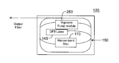
[0014] Figure 2 is a functional block diagram of an embodiment of an
optical portion
of a pulsed fiber laser source.
[0015] Figures 3A-3B are illustrations of an embodiment of a physical
implementation of a pulsed fiber laser source.
[0016] Figure 4 is a functional block diagram of an embodiment of a
ranging system
using a pulsed fiber laser source.
[0017] Figure 5 is a functional block diagram of an embodiment of a
free space
optical communication system using a pulsed fiber laser source.
[0018] Figures 6A-6B are illustrations of an example of a communication
signal in
the free space optical communication system of Figure 5.
DETAILED DESCRIPTION OF THE DISCLOSURE
[0019] A miniature pulsed fiber laser source based on a single stage Master
Oscillator
Power Amplifier (MOPA) configuration is disclosed. In one embodiment, the
pulsed fiber
laser source includes a distributed feedback (DFB) laser that supplies optical
pulses to a
Erbium/Ytterbium (Er/Yb) double clad fiber. A high power pump diode is used to
pump the
Er/Yb fiber to amplify the DFB laser output signal. A narrowband optical
filter can be used
to suppress amplified spontaneous emissions in the amplifier to allow high
amplifier gain.
The amplifier gain can be approximately 55 dB when the amplified spontaneous
emissions
are suppressed.
[0020] Figure 1 is a functional block diagram of an embodiment of a miniature
Pulsed
Fiber Laser Source (PFLS) 100. The PFLS 100 can be configured as two major
assemblies.
An optical assembly 130 can include substantially all of the optical
components. A circuit
card assembly 110 can include the majority of the electronics required to
support the optics.
4
CA 02527719 2005-11-29
WO 2004/114478
PCT/US2004/018709
A processor control logic module 120 can be coupled to the circuit card
assembly and can
provide an interface between the PFLS 100 electronics and a controller (not
shown) which
may include a processor executing software stored in memory.
[0021] The optical assembly 130 can include a first optical source coupled to
a fiber
amplifier 150 that is configured to amplify the optical output of the first
optical source. A
second optical source can be configured as a pump source for the fiber
amplifier 150. A
filter/reflector module 170 can be coupled to the fiber amplifier 150 and
configured to
suppress unwanted emissions, such as amplified spontaneous emissions (ASE).
[0022] The optical assembly 130 can include a first optical source operating
at a first
optical wavelength. The first optical source can be, for example, a DFB laser
diode140. The
first optical source need not be a DFB but can be some other type of optical
source.
[0023] In one embodiment, the DFB laser diode 140 is a uncooled laser diode
operating at
an output optical wavelength of approximately 1550 nm. The DFB laser diode 140
can be
controlled to provide a pulsed optical output that are used as seed pulses for
a subsequent
amplification stage. The DFB laser diode 140 can be configured such that it
requires no
active cooling. Because the DFB laser diode 140 may rely on passive cooling
techniques, it
may be termed an uncooled DFB laser diode 140. In other embodiments, the DFB
laser
diode may be actively cooled.
[0024] The optical output of the DFB laser diode 140 can be coupled to a fiber
amplifier
150. In one embodiment, the fiber amplifier 150 is configured as a double clad
optical fiber.
The double clad optical fiber can include a cladding layer doped with rare
earth elements,
such as rare earth elements from the Lanthanide series. The rare earth
elements can include,
for example, Erbium, Ytterbium, or some combination of Erbium and Ytterbium.
In one
embodiment, the fiber amplifier includes a dual clad Er/Yb doped optical
fiber.
[0025] The optical output of the DFB laser diode 140 can be end coupled to the
core of the
dual clad Er/Yb doped optical fiber of the fiber amplifier 150. The fiber
amplifier 150 is
configured to amplify the output of the DFB laser diode 140. The amplified
output from the
fiber amplifier 150 can be the optical output of the PFLS 100.
[0026] A second optical source operating at a second optical wavelength can be
configured
to provide a pump signal to the fiber amplifier 150. In one embodiment, the
second optical
5
CA 02527719 2005-11-29
WO 2004/114478
PCT/US2004/018709
source is a pump laser diode 160. The pump laser diode 160 can be configured
to pump a
cladding layer of the dual clad Er/Yb doped optical fiber of the fiber
amplifier 150.
[0027] The pump laser diode 160 can be selected to provide an optical output
at a second
optical wavelength that is within an absorption band of an element of a doped
layer of the
dual clad optical fiber of the fiber amplifier 150. For example, the pump
laser diode 160 may
provide an output in the absorption band of Ytterbium. The wavelength of the
pump laser
diode 160 may have a significant optical output within the band of 0.8-1.1 gm.
In another
embodiment, the pump laser diode 160 may have a significant optical output
within the band
of 920-970 rim.
[0028] The pump laser diode 160 is not required to have a narrow band optical
output and
may have a relatively broad band optical output having a bandwidth of 20 nm,
40 rim, 50 nm,
60 nm or more. The pump laser diode 160 can be uncooled or passively cooled.
That is, in
some embodiments, the pump laser diode 160 may not have any active cooling. In
other
embodiments, the pump laser diode may be actively cooled.
[0029] The pump laser diode 160 can be configured to provide an output optical
power that
is controlled in part based on an pump power control voltage. Typically, the
pump laser
diode 160 is configured to operate at maximum optical power. Although a single
pump laser
diode 160 is shown in Figure 1, other embodiments may have more than one pump
source.
for example, multiple pump laser diodes 160 can be used to pump the fiber
amplifier 150.
[0030] The pump laser diode 160 can be configured to provide approximately 1-
10 watts of
optical power. The DFB laser diode 140 can be configured to provide 1-10 mW of
average
power. In some embodiments, the DFB laser diode 140 can be configured to
provide
approximately 1 mW optical power. In other embodiments, the DFB laser diode
140 can be
configured to provide 3 mW, 5mW, 6 mW, 10 mW, less than 3 mW, less than 5 mW,
less
than 10 mW, or some other level of optical power. If the DFB laser diode 140
is configured
to provide 3 mW of optical power and the fiber amplifier 150 is configured to
provide 55 dB
of optical gain, the PFLS 100 can provide approximately +60 dBm, or
approximately 1000
watts of output optical power. The PFLS 100 can provide approximately +65 dBm,
or
approximately 3000 watts, of optical power if the DFB laser diode 140 provides
10 mW, or
+10 dBm, of optical power and the fiber amplifier 150 is configured to provide
55 dB of gain.
[0031] The optical assembly 130 can also include a filter/reflector module 170
coupled to
the fiber amplifier 150. The filter/reflector module 170 can include a filter
172, reflector 174,
6
CA 02527719 2005-11-29
WO 2004/114478
PCT/US2004/018709
or combination of filter 172 and reflector 174. The filter/reflector module
170 can be
configured to suppress undesired emission, such as scattering, Rayleigh
scattering, or ASE
that may operate to limit or other wise clamp the amount of gain available
from the fiber
amplifier 150.
[0032] The gain of a fiber amplifier 150 can be limited by the amount of ASE
generated in
the amplifier. A filter 172 having a narrow optical bandwidth can be used to
suppress the
ASE generated in the fiber amplifier 150. The filter 172 can have, for
example, a bandwidth
that is 1-5 urn, less than 3 am, less than 4 urn, or less than ,5 urn. The
filter 172 can be, for
example, a fiber Bragg grating or a thin film filter. With the ASE suppression
filter 172, the
fiber amplifier 150 can achieve a small signal gain of approximately 55 dB, as
limited by
lasing caused by double-Rayleigh scattering in the gain fiber.
[0033] To permit the PFLS 100 to operate over a large temperature range, for
example 0 to
+50 C or -20 to +50 C, a temperature tuning coefficient of the filter 172
may approximate
that of the DFB laser diode 140. Matching the filter temperature coefficient
to that of the
DFB laser diode 140 allows the filter 172 to have a narrower bandwidth than
would be used
if the filter bandwidth needed to account for variations in the DFB laser
diode 140 output.
[0034] For example, the temperature tuning of the DFB laser diode 140 may be
approximately 0.1 nm per degree C. The filter/reflector module 170 can be
configured to
package a filter 172 in a thermo-mechanical fixture. The filter/reflector
module 170 can thus
be configured such that the temperature tuning coefficient of the filter 172
approximates that
of the DFB laser diode 140.
[0035] The temperature tuning coefficient of the of the pump laser diode 160
can be of less
concern depending on the output wavelength from the device. In one of the
embodiments
described above, the pump laser diode 160 can have an output wavelength in the
band of 920-
970 urn. The wavelength of the pump laser diode 160 can be configured to be
approximately
950 nm so that it is approximately centered in the 920-970 urn band. The pump
diode laser
160 having an output wavelength of approximately 950 urn can have a relatively
large
temperature tuning coefficient without affecting the effectiveness of the
pumping energy.
The temperature tuning coefficient of the pump laser diode 160 can be
approximately 0.3 nm
per degree C. This amount of output drift has relatively little effect over
the operating
temperature range of 0 to +50 C or -20 to +50 C.
7
CA 02527719 2005-11-29
WO 2004/114478
PCT/US2004/018709
[0036] Because the pump laser diode 160 can be configured to operate over the
entire
operating temperature range, no warm-up time is required. This allows the PFLS
100 to have
a very rapid turn-on time of few ms rather than a turn-on time on the order of
several seconds
that would be otherwise required if the pump laser diode 160 needed to be
temperature
stabilized before PFLS 100 activation.
[0037] Similar benefits stem from the use of an uncooled DFB laser diode 140.
Use of an
uncooled DFB laser diode 140 can allow the PFLS 100 to maintain a relatively
high overall
power efficiency and avoid slow warm-up time that would be required if the DFB
laser diode
140 temperature needed to be stabilized before PFLS 100 turn-on.
[0038] The circuit card assembly 110 includes the electronics associated with
the optical
assembly 130. The circuit card assembly 110 include a pulse generator 112
having an output
coupled to an electrical input of the DFB laser diode 140. The pulse generator
112 can be
configured to receive a trigger signal from the processor control logic module
120.
[0039] The circuit card assembly 110 can also include a power supply 114 that
supplies the
power to the pump laser diode 160. The power supply 114 output can be coupled
to a switch
116 that selectively couples the power supply 114 output to a power supply
input of the pump
laser diode 160. The power supply 114 can be configured to convert power from
an external
power source (not shown) to a voltage and regulation that is suitable for the
pump laser diode
160. In one embodiment, the external power source is an unregulated DC power
source and
the power supply 114 is configured as a DC-DC converter. In another
embodiment, the
power supply 114 can be a linear regulator. In still other embodiments, the
external power
source can be an AC source and the power supply 114 can be an AC-DC converter.
Thus, the
power supply 114 can be virtually any type of device for converting power.
[0040] The power supply 114 can also be configured to selectively convert the
external
power based in part on control signals. In one embodiment, the power supply
114 can be
configured to receive power control and supply enable signals from the
processor control
logic module 120 that can be used to direct the power supply 114 output
voltage and can
activate the power supply 114.
[0041] The switch 116 coupled to the output of the power supply 114 can be
controlled to
selectively couple the output of the power supply 114 to the pump laser diode
160 on the
optical assembly 130. A pump enable signal from the processor control logic
module 120
can be used to selectively open or close the switch 116.
8
CA 02527719 2005-11-29
WO 2004/114478
PCT/US2004/018709
[0042] An over temperature protection module 118 can be configured to sense a
temperature of the pump laser diode 160 and can be configured to generate a
power supply
114 control signal based in part on the temperature. For example, the over
temperature
protection module 118 can be configured to disable the power supply 114 if the
sensed
temperature exceeds a predetermined threshold. In other embodiments, the over
temperature
protection module 118 can be configured to reduce the power supply 114 output
based at
least in part on a sensed temperature.
[0043] The power control logic module 120 can be used to interface an external
processor
or controller (not shown) to the circuit card assembly 110. The power control
logic module
120 can include, for example, registers, Digital to Analog Converters (DAC),
multiplexers,
and other logic that can be used to interface a controller to the circuit card
assembly 110. The
processor or controller can be configured to control the operation of the
circuit card assembly
110 and thus, the PFLS 100.
[0044] In one embodiment the DFB trigger signal can represent data that
modulates the
DFB laser diode 140. The DFB trigger signal can couple to the input of the
pulse generator
112. The pulse generator 112 can be configured to generate pulses, such as
pulses that are
approximately 10 ns in duration, in response to the DFB trigger signal. The
pulse generator
112 provides the pulses to the electrical input of the DFB laser diode 140,
which in turn
generates optical pulses at the output optical wavelength. For example, the
DFB laser diode
140 can generate 1550 nm optical pulses that are approximately 5-10 ns in
duration in
response to the 10 ns electrical pulses from the pulse generator 112.
[0045] The optical pulses output by the DFB laser diode 140 can repeat at a
predetermined
pulse repetition rate (PRF'). The pulse generator 112 may periodically receive
DFB trigger
signals at the PRF and may in turn enable the DFB laser diode 140 to produce
the pulse
pattern.
[0046] The pump laser diode 160 is turned on when the PFLS 100 receives a pump
enable
signal, such as from a processor or controller (not shown). The output power
of the pump
laser diode 160 and the output power of the PFLS 100 can be controlled by a
pump power
control signal. In one embodiment, the output of the power supply 114 is
controlled by a
pump power control voltage that can span a 0-1 V range.
[0047] Typically, the pump laser diode 160 operates at maximum optical power
unless the
end-to-end system calls for power reduction. The system may desire reduced
optical power,
9
CA 02527719 2005-11-29
WO 2004/114478
PCT/US2004/018709
for example, due to receiver saturation, presence of obstructions, or sudden
beam interruption
and saturation. The pump laser diode 160 can be configured to operate
continuously for up to
tens of seconds and can be configured to "rest" between two consecutive
continuous
operations to allow for cooling. The operation duty cycle can be configured to
be less than or
approximately equal to 50%. For example, the operational duty cycle can
include a 30
second resting time between 30 second continuous operation to provide
essentially a 50%
duty cycle. To further reduce the power consumed, the pump laser diode 160 can
be
energized at a duty cycle that approximately matches the PRF of the pulsed DFB
laser diode
140. Thus, during the period of time that the pump laser diode 160 is
considered to be active
or operational, the pump laser diode 160 is energized at approximately the PRF
of the DFB
laser diode 140.
[0048] Figure 2 is a functional block diagram of an embodiment of the optical
assembly
130 showing the relative relationship of the optical components. The optical
assembly 130
can be, for example, the optical assembly 130 of the PFLS 100 of Figure 1. The
DFB laser
diode 140 can be positioned to end couple an optical signal to the core of a
dual clad Er/Yb
doped optical fiber that is used as the fiber amplifier 150. The length of
optical fiber can be,
for example, coiled around the outside perimeter of the optical assembly 130
in order to
maximize the bend radius available for the optical fiber.
[0049] A V-groove pump module 260 can be configured to couple the energy from
the
pump laser diode (not shown) to a v-groove location on a loop of fiber passing
through the V-
groove pump module 260. The pump laser diode within the V-groove pump module
260 can
be configured to pump a doped cladding layer of the optical fiber. In an
embodiment, the
pump laser diode is configured to side pump an Er/YU clad layer of the optical
fiber. The
pump laser diode can be configured, for example, to v-groove side pump the
Er/Yb clad layer
of the optical fiber. A v-groove can be positioned on a location of the fiber
and the pump
laser diode and a collimator lens (not shown) can be positioned to illuminate
a fave of the v-
groove. The V-groove pump module 260 can use more than one v-groove coupled
source.
For example, a plurality of pump laser diodes can each be configured to
illuminate a
corresponding v-groove positioned on the fiber. The v-groove side pump
configuration can
be used for high coupling efficiency and compact packaging.
[0050] The filter/reflector module 170 can be coupled to the fiber amplifier
150 and can
suppress the ASE generated by the fiber amplifier 150. In one embodiment, the
CA 02527719 2005-11-29
WO 2004/114478
PCT/US2004/018709
filter/reflector module 170 is coupled to an end of the fiber amplifier 150
opposite the DFB
laser diode 140. An optical output can be coupled from the fiber amplifier
150. In another
embodiment, the optical output can be coupled to the end of the fiber
amplifier 150 opposite
the DFB laser diode 140 and the filter/reflector module 170 can be coupled to
the fiber
amplifier 150 using, for example, a Wavelength Division Multiplexer (WDM). An
optical
circulator (not shown) can be positioned in the output fiber to reduce the
effects of external
reflections. In another embodiment, a loop of the fiber passes through a
narrowband filter in
the filter module.
[0051] Figures 3A-3B are illustrations of an embodiment of a PFLS 100
assembly. Figure
3A illustrates an embodiment of an optical half of the PFLS 100 assembly and
Figure 3B
illustrates an embodiment of an electronic half of the PFLS 100 assembly.
[0052] Figure 3A shows the optical half of the PFLS 100. The optical assembly
130 is
located in one half of a housing 310, which may be an aluminum housing. The
optical
assembly 130 of the embodiment shown in Figure 3A is approximately 60 mm x 43
mm. The
entire PFLS 100 can be packaged in a housing 310 that is less than
approximately 20 mm
high to result in a complete PFLS 100 assembly of less than 52 cm3.
Additionally, the
electrical and optical design of the PFLS 100 allows the assembly to use on
the order of few
tens of watts.
[0053] Splitting the PFLS 100 into an optical half and an electrical half
allows the PFLS
100 to be manufactured in a compact size. Because the optical assembly 130 and
electrical
circuit card assembly 110 are physically separated, each assembly can be
fabricated, tested or
otherwise qualified, repaired, or replaced independently of the other
assembly.
[0054] The optical assembly 130 includes the DFB laser diode 140 driving a
core of the
fiber amplifier 150. The pump laser diode 160 is configured to v-groove side
pump the fiber
amplifier 150. The filter/reflector module 170 is positioned physically close
to the DFB laser
diode 140 such that the filter/reflector module 170 is exposed to
approximately the same
temperature as the DFB laser diode 140. An optical circulator 320 can be
positioned in the
output fiber.
[0055] Figure 3B illustrates an embodiment of the circuit card assembly 110
positioned in
the side of the housing 310 opposite the optical assembly 130 shown in Figure
3A. To
maintain the compact size of the PFLS 100, the circuit card assembly 110 can
be
manufactured with surface mount devices. Surface mount devices can also reduce
the cost to
11
CA 02527719 2005-11-29
WO 2004/114478
PCT/US2004/018709
manufacture the circuit card assembly and may be more resistant to damage by
Electro Static
Discharge (ESD).
[0056] Figure 4 is a functional block diagram of a PFLS 100 integrated in to
an optical
communication unit referred to as an interrogator (INT) 400 that can be
configured to
perform 1) ranging to cooperative and non-cooperative targets, 2) locating one
or more
targets, 3) identifying one or more targets and 4) communicating with one or
more targets.
The interrogator 400 includes a processor control module 410 that is coupled
to a PFLS 100.
The PFLS 100 can be, for example, the PFLS 100 of Figure 1 packaged as shown
in Figure 3.
The processor control module 410 can be configured to generate the data and
control signals
used by the PFLS 100. The interrogator 400 also includes a receiver 420 which
can be an
optical receiver that is configured to receive a signal at approximately the
same wavelength
that is transmitted by the PFLS 100.
[0057] The interrogator 400 can be configured to perform ranging to a target
illuminated by
the PFLS 100. The range can be determined by a number of techniques. For
example, the
interrogator 400 can determine a range by determining a time delay of arrival
of a signal
transmitted to a target and reflected to the receiver 420.
[0058] The target space illuminated by the PFLS 100 can include a number of
objects. For
example the target space illuminated by the PFLS 100 can include non-
cooperative targets
434 and 436 as well as cooperative targets 432. A non-cooperative target, for
example 434,
can be any target that is not configured to be reflective or otherwise
responsive to the signal
emanating from the PFLS 100. Non-cooperative targets can include man made
objects, such
as a building or structure, or some other non-cooperative target 434, as well
as naturally
occurring objects, such as a stand of trees 436 or a terrestrial feature.
[0059] Since non-cooperative targets, for example trees 436, typically have
low surface
reflectivity and undefined shapes, the reflected optical signal is weaker and
spreads over
larger area than signals reflected by cooperative targets 432. Therefore,
ranging to non-
cooperative targets can present a challenge to systems using low optical
power. The problem
is further worsened in the presence of atmospheric attenuations.
[0060] In the embodiment shown in Figure 4, the interrogator 400 can be
configured to
range to the cooperative target 432 located in the presence of reflective
elements such as trees
436, ground and buildings, or some other non-cooperative target 434. The PFLS
100 high-
power and narrow laser pulses permit the interrogator 400 to range to
distances much longer
12
CA 02527719 2005-11-29
WO 2004/114478
PCT/US2004/018709
than traditional lower-power signals, discriminate between the cooperative
target 432 and its
surrounding area, including the non-cooperative targets 434 and 436. The high
power narrow
PFLS 100 output allows the interrogator 400 to operate in presence of
atmospheric
attenuation such as fog, rain, and haze. For instance, if the building or some
other non-
cooperative target 434 has 50% reflectivity, covers 75% of the transmit beam
and is placed at
half the distance between the interrogator 400 and the desired cooperative
target 432, the
interrogator 400 can still locate the cooperative target 432.
[0061] Figure 5 is a functional block diagram of an embodiment in which the
interrogator
400 having the PFLS 100 is configured in an optical communication system, such
as an
optical combat system. In optical an combat system, the cooperative target 432
of Figure 4 is
an active target and is referred to as a tag 510. The tag 510 can include a
modulating retro-
reflector element (MRR) 540. The MRR can include a corner cube reflector (CCR)
and
modulator 530.
[0062] The communication between the interrogator 400 and the tag 510 can be
hi-
directional and asynchronous. The communication protocol can be configured to
allow the
tag 510 subsystems to tune to interrogator 400 wavelength. By using the PFLS
100 high-
power optical output having narrow-pulses, the communication can be optimized.
The tag
510 receiver 520, MRR modulator 540 and interrogator 400 receiver 420 can be
synchronized
to the incoming pulses by windowing the signal processing interval. This
feature can
minimize internal noise and channel degradation effects.
[0063] The high PFLS 100 power allows the system to have high operating link
margins in
the forward link (from interrogator 400 to tag 510) and roundtrip link
(interrogator 400 to
MRR 540 and back to interrogator 400) to combat atmospheric attenuations
during
communication.
[0064] The high PFLS 100 optical power also allow the interrogator 400 to
better assess
channel condition to optimize communication parameters and monitor channel
degradation.
Although passive cooling within the PFLS 100 is typically sufficient for
operating in most
systems, the PFLS 100 can implement larger passive heatsinks or active cooling
elements to
enable the communication between interrogator 400 and tag 510 to be
continuous.
Continuous operation allows the system to support long duration real-time data
transfer. The
integration of larger heatsin_ks or active cooling allows continuous operation
but comes at the
cost of packaging size or increased power consumption.
13
CA 02527719 2005-11-29
WO 2004/114478
PCT/US2004/018709
[0065] A temperature discrepancy between the interrogator 400 and the tag 510
locations
can be resolved by characterizing the PFLS 100 wavelengths drift with
temperature. A
lookup table can be implemented in the tag 510 to allow the tag 510 subsystems
to precisely
tune to the PFLS 100 wavelength.
[0066] Figure 6A shows a functional diagram of an embodiment of an
interrogator 400
operating in the presence of adverse atmospheric conditions such as fog 602 or
rain. The
PFLS 100 in response to control of the processor control module 410 can
transmit one or
more narrow optical pulses 610. The optical pulse 610 can be, for example a 5-
10 ns
duration optical pulse of approximately 1550 nm wavelength. In the presence of
fog 602, the
sharp transmitted optical pulse 610 can be simultaneously reflected by the
cooperative target
432 and fog 602.
[0067] Figure 6B illustrates an example of the pulse that is received at the
receiver 420 in
the operating condition shown in Figure 6A. The reflected pulse includes a
component that is
spread in time 620, in part due to the dispersive effects of fog 602, and has
a sharp peak 622
corresponding to the cooperative target 432 or tag having relatively high
surface reflectivity.
The interrogator 400 can use the reflected pulse characteristics to define the
communication
channel condition and set the PFLS 100 optical power accordingly.
[0068] Due to the high-level of optical power and pulse repetition frequency
(PRF)
supported by the PFLS 100, an automatic power reduction (APR) mechanism can be
implemented within the interrogator 400 to comply with a predetermined system
eye-safety
requirement. This feature is implemented by detecting sudden beam interruption
or receiver
saturation and adjusting the PFLS 100 optical power in response to detecting
the occurrence
of the predetermined events. The interrogator 400 can initially be configured
to operate the
PFLS 100 at full optical power. The processor control module 410 can be
configured to
operate the pump laser diode at its maximum output power. Additionally, the
DFB laser
diode and pump laser diode can operate at a maximum PRF. The receiver 420
within the
interrogator 400 can monitor the reflections to perform ranging or optical
communications.
The receiver 420 can be configured to detect a beam interruption or receiver
saturation, in
part, by measuring the power of the received optical signal. In response to a
sudden beam
interruption, the received signal can suddenly increase in power. Similarly,
the receiver 420
may saturate if the amount of transmit power is much greater than required to
determine
ranging to a target. In both of the conditions, the PFLS 100 can reduce the
output optical
14
CA 02527719 2005-11-29
WO 2004/114478
PCT/US2004/018709
power for eye safety issues. The receiver 420 may detect sudden beam
interruption or
saturation and may report the condition to the processor control module 410 or
directly to the
PFLS 100. The processor control module 410 or the PFLS 100 can then reduce the
output
optical power. For example, the processor control module 410 or the PFLS 100
may reduce
the pump laser diode power or may reduce the PRF or both.
[0069] In one embodiment, the PFLS 100 PRF and pump power can be adjusted such
that
the overall transmitted optical energy complies with values consistent with
safety
requirements or standards. Typically, the interrogator 400 can be configured
to operate in
various predetermined modes with at least one of the modes complying with the
eye-safety
requirements. The interrogator 400 can revert to eye-safe modes upon beam
interruption and
saturation.
[0070] The above description of the disclosed embodiments is provided to
enable any
person skilled in the art to make or use the disclosure. Various modifications
to these
embodiments will be readily apparent to those skilled in the art, and the
generic principles
defined herein may be applied to other embodiments without departing from the
scope of the
disclosure. Thus, the disclosure is not intended to be limited to the
embodiments shown
herein but is to be accorded the widest scope consistent with the principles
and novel features
disclosed herein.