Sélection de la langue

Search

Sommaire du brevet 2528518 

Énoncé de désistement de responsabilité concernant l'information provenant de tiers

Une partie des informations de ce site Web a été fournie par des sources externes. Le gouvernement du Canada n'assume aucune responsabilité concernant la précision, l'actualité ou la fiabilité des informations fournies par les sources externes. Les utilisateurs qui désirent employer cette information devraient consulter directement la source des informations. Le contenu fourni par les sources externes n'est pas assujetti aux exigences sur les langues officielles, la protection des renseignements personnels et l'accessibilité.

Disponibilité de l'Abrégé et des Revendications

L'apparition de différences dans le texte et l'image des Revendications et de l'Abrégé dépend du moment auquel le document est publié. Les textes des Revendications et de l'Abrégé sont affichés :

  • lorsque la demande peut être examinée par le public;
  • lorsque le brevet est émis (délivrance).
(12) Demande de brevet: (11) CA 2528518
(54) Titre français: POMPE A NUTATION HYBRIDE
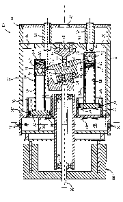
(54) Titre anglais: HYBRID NUTATING PUMP
Statut: Réputée abandonnée et au-delà du délai pour le rétablissement - en attente de la réponse à l’avis de communication rejetée
Données bibliographiques
(51) Classification internationale des brevets (CIB):
  • F01B 13/04 (2006.01)
(72) Inventeurs :
  • LYNN, WILLIAM HARRY (Etats-Unis d'Amérique)
  • FUKSA, RICHARD C. (Etats-Unis d'Amérique)
(73) Titulaires :
  • THOMAS INDUSTRIES INC.
(71) Demandeurs :
  • THOMAS INDUSTRIES INC. (Etats-Unis d'Amérique)
(74) Agent: GASTLE AND ASSOCIATES
(74) Co-agent:
(45) Délivré:
(86) Date de dépôt PCT: 2004-06-18
(87) Mise à la disponibilité du public: 2004-12-29
Requête d'examen: 2009-06-16
Licence disponible: S.O.
Cédé au domaine public: S.O.
(25) Langue des documents déposés: Anglais

Traité de coopération en matière de brevets (PCT): Oui
(86) Numéro de la demande PCT: PCT/US2004/019467
(87) Numéro de publication internationale PCT: US2004019467
(85) Entrée nationale: 2005-12-06

(30) Données de priorité de la demande:
Numéro de la demande Pays / territoire Date
60/479,413 (Etats-Unis d'Amérique) 2003-06-18

Abrégés

Abrégé français

La présente invention concerne une pompe à nutation comprenant un accouplement universel du type en croix qui relie un élément oscillant à un boîtier de pompe, des joints sphériques couplant l'élément oscillant aux tiges de piston, lesdites tiges de piston étant fixées aux têtes de piston de sorte que les têtes de piston oscillent dans les cylindres de la pompe.


Abrégé anglais


A nutating pump has a cross-type universal joint connecting a nutating member
to a pump housing, ball joints connecting the nutating member to piston rods,
and the piston rods fixed to piston heads so that the piston heads wobble in
pump cylinders.

Revendications

Note : Les revendications sont présentées dans la langue officielle dans laquelle elles ont été soumises.


I claim:
1. A nutating pump comprising:
a pump housing;
a prime mover having a drive shaft with a shaft axis, the drive shaft being
driven by the
prime mover about the shaft axis relative to the pump housing;
a plurality of pumping cylinders with axes radially disposed about and
generally parallel
with the shaft axis, said pumping cylinders being fixed relative to the pump
housing;
a plurality of wobble pistons, one said wobble piston for each pumping
cylinder, each
said wobble piston having a piston head and a piston rod fixedly connected to
the piston head,
each said piston head being received in the associated pumping cylinders in a
fit that permits
wobbling motion of the piston head relative to the pumping cylinder as the
piston is reciprocated;
a wobble member connected to the piston rods; and
a universal joint connecting the wobble member to the housing.
2. A nutating pump as claimed in claim 1, wherein the nutating member is
connected
to the piston rods with a ball and socket joint.
3. A nutating pump as claimed in claim 2, wherein each ball and socket joint
includes a fixed member and a biased member.
4. A nutating pump as claimed in claim 3, wherein the fixed members transmit a
force of pumping between the wobble member and the wobble pistons during a
power stroke of
the wobble piston.
5. A nutating pump as claimed in claim 3, wherein the wobble member is
positioned
axially between the fixed member and the head of the wobble piston for vacuum
pistons of the
pump.
-7-

6. A nutating pump as claimed in claim 1, wherein piston rods of the wobble
pistons
are hollow.
7. A nutating pump as claimed in claim 6, wherein the piston rods contain the
ball
and socket joint.
8. A nutating pump as claimed in claim 7, wherein the piston rods contain
springs
that bias parts of the ball and socket joints together.
9. A nutating pump as claimed in claim 1, wherein each piston rod is longer
than the
distance from the axis of the drive shaft to an axis of a cylinder associated
with the piston rod.
10. A nutating pump as claimed in claim 1, wherein each piston head has a cup
seal
that forms a sliding seal with the associated pumping cylinder.
-8-

Description

Note : Les descriptions sont présentées dans la langue officielle dans laquelle elles ont été soumises.

CA 02528518 2005-12-06
WO 2004/113724 PCT/US2004/019467
HYBRID NUTATING PUMP
CROSS-REFERENCE TO RELATED APPLICATION
[0001]
STATEMENT CONCERNING FEDERALLY SPONSORED
RESEARCH OR DEVELOPMENT
[0002] Not applicable.
FIELD OF THE INVENTION
[0003] This invention relates to pumps, and in particular, to nutating pumps.
BACKGROUND OF THE INVENTION
[0004] Nutating pumps having a nutating member that has a circular rocking or
wobble
type of motion to reciprocate pistons so as to result in pumping action are
known. For example,
U.S. Patent No. 5,007,385 discloses such a mechanism that uses either a
spherical bearing or
alternatively a cross-type universal joint between the wobble member and the
housing. The
wobble member is driven eccentrically ~by a drive shaft and has arms joined by
b 1l joints or
other pivot joints to pistons that reciprocate linearly.
[0005] These types of mechanisms have typically had many sliding surfaces and,
therefore, many bearings, each making the whole construction relatively
complex, difficult to
assemble, and expensive.
SUMMARY OF THE INVENTION
[0006] The invention provides a nutating pump in which a cross-type universal
joint
connects the nutating member to the housing, ball joints connect the nutating
member to the

CA 02528518 2005-12-06
WO 2004/113724 PCT/US2004/019467
piston rods, and the piston rods are fixed to the piston heads so that the
piston heads wobble in
the pump cylinders. This eliminates a bearing connection between the piston
rod and the piston
head, while achieving the benefits of using a universal joint to connect the
nutating member to
the housing to take side loads off of the piston heads.
[0007] In another aspect of the invention, the piston rods are made relatively
long so as to
minimize the wobble motion of the piston heads in the pump cylinders. The
longer that the
piston rods can be made, the less that the piston heads will wobble in the
pump cylinders. In
other words, for example for a 12° tilt angle of the universal joint,
with a sufficiently long piston
rod, the piston head will only tilt 1 °. Such a low tilt of the piston
head from being axially
aligned in the pump cylinder allows the use of either a piston cup, as is
common in wobble
pistons, or of a split-ring seal (a split-ring being of the type that is
commonly used in internal
combustion reciprocating engines and some reciprocating pumps). Split-ring
seals are generally
regarded as providing very long wear-life and low blow-by leakage, whereas a
wobble piston
cup provides adequate sealing with a relatively larger angle of tilt of the
wobble piston head.
[0008] It is desirable to use a universal joint to connect the nutating member
to the
housing.ube~au-s~-the -uni--versal~ joi-nt is oapable-of -ear-tying the tar-
~iQnal--laading to wltiuh tha
wobble member is subjected, reducing side loading on the pistons.. Side
loading on the pistons
results in increased wear, shorter life, and more blow-by leakage over the
life of the pump.
[0009] In addition, a long stroke which is enabled by the IJ joint and also by
the use of
the socket joints to connect the wobble member to the piston rods provides
higher flow in a small
space, which is significantly higher than other types of nutating pump
designs. Allowing use of
split-ring seals instead of piston cups also helps reduce frictional loading
and provides better
efficiency.

CA 02528518 2005-12-06
WO 2004/113724 PCT/US2004/019467
[0010] The foregoing and other objects and advantages of the invention will
appear in the
detailed description which follows. In the description, reference is made to
the accompanying
drawings which illustrate a preferred embodiment of the invention.
BRIEF DESCRIPTION OF THE DRAWINGS
[0011] Fig. 1 is a cross-sectional, schematic view taken on a 90° cross-
section line
illustrating a pump incorporating the invention.
DETAILED DESCRIPTION OF THE PREFERRED EMBODIMENT
[0012] A pump 10 of the invention has a housing 12 which may be made in any
number
of pieces, a pair of compression pistons 14 opposite from one another (only
one shown, the other
one would be 180° apart from the one shown, Fig. 1 being a 90°
cross-sectional view), a pair of
vacuum pistons 16 (only one shown, the other vacuum piston 16 being opposite
from the one
shown, 180° spaced therefrom about the axis of drive shaft 18). Each
piston 14, 16 has a head
14A or 16A and a rod 14B or 16B, respectively. The heads 14A and 16A
reciprocate with a
slight wobble motion in respective pump cylinders 20 and 22. Heads 14A and 16A
have
respective split ring seals 14C, 16C, preferably made of a
polytetrafluoroethylene composite
material; that- establish- a sliding seal--wrth -the walls° o~-the--
cylinders 2022- and- are preferably
radiused on their outside surfaces with a radius equal to the cylinder radius
to maintain good
sealing as the piston wobbles in the cylinder. Intake valve 24 and exhaust
valve 26 are provided
respectively to and from the pumping chamber in cylinder 20 and intake valve
28 and exhaust
valve 30 are provided respectively to and from the pumping chamber in the
cylinder 22. The
invention could also be applied to a pressure-only or a vacuum-only pump, and
in that case it
would be desirable to provide an odd number of pistons, e.g., three or five,
to minimize gas
pulsations.
-3-

CA 02528518 2005-12-06
WO 2004/113724 PCT/US2004/019467
[0013] Intake air for cylinder 20 comes into intake chamber 34 through holes
36 and
compressed air exits cylinder 20 past valve 26 into exhaust chamber 36 and
from exhaust
chamber 36 through connector tube 38 which, as indicated by dashed line 40, is
in
communication with the chamber 36. Intake for the vacuum cylinder 22 comes
through hole 42
into sound attenuator housing 44 and through holes 46 into the interior of the
housing 12 where it
can pass through the piston head 16A past the valve 28 into the pumping
chamber of the cylinder
22. Compressed exhaust air from the vacuum cylinder 22 passes by valve 30 into
exhaust
chamber 48 and out of exhaust chamber 48 either through holes 50 or
alternatively through a
connector tube 52 that, as illustrated by the dashed line 54 is in
communication with the chamber
48. The connector tubes 38 and 52 pass through the attenuator chamber 44 so
that all the
connections for the pump, including the intake 42 to the vacuum chamber arid
the exhausts from
the pressure and vacuum pumps, can all be provided at the end of the pump. If
desired, a
connector tube like the tubes 38 and 52 could also be provided for the intake
for the pressure
cylinder 20.
[0014) A cross-type universal joint 56 has two of its opposed arms journalled
to
eanneetor ~8--andrthe--=other--two of its opposed arms-{~l~ieh---are at..90-~
to the--frrst-twa. opposed-
arms mentioned) journalled to wobble member 60. "Opposed" as used herein means
that the two
arms are 180° apart. Wobble member 60 mounts the outer race of a
bearing 62 at its end wluch
is opposite from the universal joint 56 and the inner race of the bearing is
pressed onto an
eccentric stub shaft 64 which is fixed off center and at an angle to drive
shaft 18. Drive shaft 18
is driven by motor 68 which has its stator fixed to the housing 12 and is
journalled by bearings
70 to the housing 12. The center of the universal joint 56 is on the axis of
shaft 18. When the
shaft 18 is rotated, the universal joint 56 permits the eccentric 64 to impart
a wobbling motion to
-4-

CA 02528518 2005-12-06
WO 2004/113724 PCT/US2004/019467
the wobble member 60 such that the two compression pistons 14 (which are
180° relative to each
other about the axis of shaft 18) are 180° out of phase with one
another and the two vacuum
pistons 16, which are at 90° to the compression pistons 14 about the
axis of shaft 18 (and which
are 180° relative to each other about the axis of shaft 18), are
180° out of phase with one another.
[0015] The wobble member 60 has arms 74 which extend from it to the four
piston rods
14B and 16B. The arms 74 extend into the respective piston rods and at their
ends have ball
heads 76. The piston rods 14B and 16B are hollow and contain within them each
a fixed socket
half 78 and a biased socket half 80. Each fixed socket half 78 of the
compressor piston rods 14B
is held at a constant spacing from the piston head 14A by a spacer tube 82
which is contained
within the rod 14B and the fixed socket half 78 of the vacuum piston rod 16B
is held at a fixed
spacing from the vacuum piston head 16A by the rod 16B being crimped over at
its end 84.
Biased socket half 80 of each compression piston rod 14B is biased toward the
ball head 76 and
toward the piston head 14A by a spring 86 which is held in the rod 14B by the
crimp.at end 84.
The socket half 80 of the vacuum piston 16 is biased against the ball head 76
and away from the
piston head 16A by a spring 86, which has its other end acting against a
spacer tube 88 inside
eael~t-pi-stun-rod 1-6B. The -springs -86 provide a-pr~load~ on the b-all=-
heads 76 and ar-e-ncrt-subj ected-
to forces (other than the ones they exert) on the working strokes of the
respective pistons. That
is because a rigid connection is provided between the ball head 76 and the
compressor piston
head 14A by the spacer tube 82 and socket half 78 on the power stroke of the
compressor piston
(i.e. going toward top dead center) and a rigid connection is provided between
the ball head 76
and the vacuum piston head 16A on its power stroke (i.e. going toward bottom
dead center) by
the socket half 78 and the piston rod 16B being crimped over it.
Alternatively, the ball and
-5-

CA 02528518 2005-12-06
WO 2004/113724 PCT/US2004/019467
socket joint could be reversed, with the balls on the piston rods 14B, 16B and
the sockets on the
wobble member 60.
[0016] A preferred embodiment of the invention has been described in
considerable
detail. Many modifications and variations to the preferred embodiment
described will be
apparent to a person of ordinary skill in the art. For example, split ring
seals rather than cup
seals could possibly be employed if the the piston rods were made long enough
or the wobble of
the piston was otherwise reduced to make split ring seals practical.
Therefore, the invention
should not be limited to the embodiment described.
_g_

Dessin représentatif
Une figure unique qui représente un dessin illustrant l'invention.
États administratifs

2024-08-01 : Dans le cadre de la transition vers les Brevets de nouvelle génération (BNG), la base de données sur les brevets canadiens (BDBC) contient désormais un Historique d'événement plus détaillé, qui reproduit le Journal des événements de notre nouvelle solution interne.

Veuillez noter que les événements débutant par « Inactive : » se réfèrent à des événements qui ne sont plus utilisés dans notre nouvelle solution interne.

Pour une meilleure compréhension de l'état de la demande ou brevet qui figure sur cette page, la rubrique Mise en garde , et les descriptions de Brevet , Historique d'événement , Taxes périodiques et Historique des paiements devraient être consultées.

Historique d'événement

Description Date
Le délai pour l'annulation est expiré 2011-06-20
Demande non rétablie avant l'échéance 2011-06-20
Réputée abandonnée - omission de répondre à un avis sur les taxes pour le maintien en état 2010-06-18
Lettre envoyée 2009-07-30
Requête d'examen reçue 2009-06-16
Exigences pour une requête d'examen - jugée conforme 2009-06-16
Toutes les exigences pour l'examen - jugée conforme 2009-06-16
Lettre envoyée 2006-10-19
Inactive : Transfert individuel 2006-09-26
Inactive : Page couverture publiée 2006-02-14
Inactive : Lettre de courtoisie - Preuve 2006-02-14
Inactive : Notice - Entrée phase nat. - Pas de RE 2006-02-07
Demande reçue - PCT 2006-01-16
Exigences pour l'entrée dans la phase nationale - jugée conforme 2005-12-06
Demande publiée (accessible au public) 2004-12-29

Historique d'abandonnement

Date d'abandonnement Raison Date de rétablissement
2010-06-18

Taxes périodiques

Le dernier paiement a été reçu le 2009-06-16

Avis : Si le paiement en totalité n'a pas été reçu au plus tard à la date indiquée, une taxe supplémentaire peut être imposée, soit une des taxes suivantes :

  • taxe de rétablissement ;
  • taxe pour paiement en souffrance ; ou
  • taxe additionnelle pour le renversement d'une péremption réputée.

Les taxes sur les brevets sont ajustées au 1er janvier de chaque année. Les montants ci-dessus sont les montants actuels s'ils sont reçus au plus tard le 31 décembre de l'année en cours.
Veuillez vous référer à la page web des taxes sur les brevets de l'OPIC pour voir tous les montants actuels des taxes.

Historique des taxes

Type de taxes Anniversaire Échéance Date payée
Taxe nationale de base - générale 2005-12-06
TM (demande, 2e anniv.) - générale 02 2006-06-19 2006-06-14
Enregistrement d'un document 2006-09-26
TM (demande, 3e anniv.) - générale 03 2007-06-18 2007-06-05
TM (demande, 4e anniv.) - générale 04 2008-06-18 2008-06-05
TM (demande, 5e anniv.) - générale 05 2009-06-18 2009-06-16
Requête d'examen - générale 2009-06-16
Titulaires au dossier

Les titulaires actuels et antérieures au dossier sont affichés en ordre alphabétique.

Titulaires actuels au dossier
THOMAS INDUSTRIES INC.
Titulaires antérieures au dossier
RICHARD C. FUKSA
WILLIAM HARRY LYNN
Les propriétaires antérieurs qui ne figurent pas dans la liste des « Propriétaires au dossier » apparaîtront dans d'autres documents au dossier.
Documents

Pour visionner les fichiers sélectionnés, entrer le code reCAPTCHA :


Pour visualiser une image, cliquer sur un lien dans la colonne description du document. Pour télécharger l'image (les images), cliquer l'une ou plusieurs cases à cocher dans la première colonne et ensuite cliquer sur le bouton "Télécharger sélection en format PDF (archive Zip)" ou le bouton "Télécharger sélection (en un fichier PDF fusionné)".

Liste des documents de brevet publiés et non publiés sur la BDBC .

Si vous avez des difficultés à accéder au contenu, veuillez communiquer avec le Centre de services à la clientèle au 1-866-997-1936, ou envoyer un courriel au Centre de service à la clientèle de l'OPIC.


Description du
Document 
Date
(aaaa-mm-jj) 
Nombre de pages   Taille de l'image (Ko) 
Description 2005-12-05 6 260
Revendications 2005-12-05 2 58
Abrégé 2005-12-05 2 71
Dessins 2005-12-05 1 43
Dessin représentatif 2006-02-09 1 18
Rappel de taxe de maintien due 2006-02-20 1 111
Avis d'entree dans la phase nationale 2006-02-06 1 193
Courtoisie - Certificat d'enregistrement (document(s) connexe(s)) 2006-10-18 1 105
Rappel - requête d'examen 2009-02-18 1 117
Accusé de réception de la requête d'examen 2009-07-29 1 174
Courtoisie - Lettre d'abandon (taxe de maintien en état) 2010-08-15 1 172
PCT 2005-12-05 1 61
Correspondance 2006-02-06 1 26
Taxes 2006-06-13 1 47
Taxes 2007-06-04 1 49
Taxes 2008-06-04 2 68
Taxes 2009-06-15 2 64