Note : Les descriptions sont présentées dans la langue officielle dans laquelle elles ont été soumises.
CA 02528985 2006-02-06
350P1CA
SAFETY RAILING FOR BUILDING CONSTRUCTION
The present invention relates to methods of installing safety railings in
buildings under
construction, to safety railings and to post support for use in safety
railings.
In the construction of a multi-floor concrete building, concrete floor
formworks are employed
for the casting of the floors in succession. As each floor is cast, it is
necessary to install a
temporary safety railing around the periphery of that floor, so that workers
are prevented
from falling from that floor. When the work on that floor by the workers has
been
completed, the safety railing is removed.
At present, the conventional method of installing such a safety railing is to
secure brackets
by nailing the brackets to the columns of the building under construction.
These brackets are
then employed to support horizontal rails. Also, it is common to gather scrap
lumber on a
building site and to employ it to make posts, with feet projecting
horizontally from the posts,
the feet being reinforced by triangular pieces of plywood secured to the feet
and to the posts.
With the posts positioned on a newly cast concrete floor at a spacing of eight
feet, holes are
then drilled through the feet into the underlying concrete floor and lengths
of rebar wire and
nails are inserted to anchor the feet and, thereby, the posts to the concrete.
Wooden rails are
then nailed to the posts or supported in the posts by brackets fashioned from
scrap wood and
nailed to the posts.
It is, however, a disadvantage of this prior method that it is very labor
intensive, since in
practice it is usually necessary to have such railing installation performed
by at least one
construction worker, who is dedicated to that task and who is normally kept so
busy by this
work that he is unavailable for other work on the building site.
CA 02528985 2005-12-06
-2-
Also, the drilling into the concrete involves the risk of breakage and
consequential repairs
and may cause damage to wiring or pipes embedded in the concrete.
According to the present invention, there is provided a method of installing a
safety railing
in a building under construction by mounting open-topped post sockets on
socket supports
on a concrete floor formwork with the post sockets spaced above the concrete
floor
formwork by the socket supports, casting concrete to form a concrete floor on
the concrete
floor formwork and thereby embedding the post sockets and the socket supports
in the
concrete floor with the concrete extending beneath said post sockets,
inserting lower ends
of posts in the post sockets to support the posts above the concrete floor and
supporting rails
on the posts.
With the method according to the present invention, there is no need to drill
into the concrete
floor or the walls or columns of the building and, therefore, no risk of
damage caused by
such drilling. Also, there is a substantial saving of work as compared with
the above-
described conventional method of installing safety railings.
Because the post sockets are supported above the concrete floor formwork, by
the socket
supports, during the casting of the floor, the concrete can flow beneath the
post sockets so
that, when the concrete has cured, the post sockets are supported on the
concrete which has
become located beneath the post sockets.
The socket supports extend to the underside of the newly cast concrete floor,
which in
accordance with conventional building construction practice is then ground
prior to the
application of a finish layer to the underside of the concrete floor. The
grinding operation
serves to smoothen any projection by the lower ends of the socket supports at
the underside
of the concrete floor.
CA 02528985 2006-02-06
-3-
The socket supports may have lower ends which are downwardly tapered so that
only a small
amount, if any, of the post supports projects at the underside of the concrete
floor before the
grinding operation.
During the casting of the concrete to form the concrete floor, the post
sockets can be covered
by lids, which prevent concrete from entering into the post sockets and which,
thereby,
facilitate the insertion of the posts into the post sockets. These lids are
then removed before
the insertion of the posts into the post sockets. When the safety railing is
no longer required
on the concrete floor, the rails and the posts can be removed. The post
sockets are then filled
and concealed by the application of a finish layout onto the top of the
concrete floor.
Also in accordance with the present invention, there is provided a post
support for a safety
railing, the post support comprising a post socket having an upwardly open top
and a socket
support extending downwardly from the post socket, the socket support
comprising support
members each having a foot portion extending laterally of the respective
support member.
Further, according to the present invention, there is provided a safety
railing on a concrete
floor in a building under construction, the safety railing comprising a
plurality of open-
topped post sockets embedded in the concrete floor with the concrete of the
concrete floor
extending beneath the post sockets, the post sockets each having a post socket
support
extending downwardly from the post socket and terminating at an underside of
the concrete
floor, posts inserted into and extending upwardly from the post sockets and
rails supported
on the posts.
In a preferred embodiment of the invention, the socket support comprises a
plurality,
preferably three, of support members each having a lower end formed with a
foot extending
laterally from the respective support member and having a downwardly tapered
underside.
After the post sockets have been embedded in the concrete floor, most of the
support
CA 02528985 2006-02-06
-4-
members are above the underside of the concrete floor, and any small portion
of the
downwardly tapered undersides of the foot portions is readily removable by
grinding.
The invention will be more readily understood from the following description
of an
embodiment thereof given, by way of example only, with reference to the
accompanying
drawings, in which:-
Figure 1 shows a view in perspective of a safety railing according to an
embodiment of the
present invention on a broken-away portion of a concrete floor;
Figure 2 shows a view in perspective of a post socket forming part of the
safety railing of
Figure 1;
Figures 3 and 4 show, respectively, a view in side elevation and a plan view
of the post
socket of Figure 2;
Figure 5 shows a view in perspective of a post forming part of the safety
railing of Figure 1;
Figure 6 shows a broken-away view, in side elevation, of parts of the post of
Figure 5;
Figure 7 shows a broken-away view, in side elevation, of a part of the post of
Figure 5,
including a rail support bracket;
Figure 8 shows a view in perspective of the rail support bracket of Figure 7;
Figure 9 shows a plan view of a toe kick bracket on the post of Figure 5;
Figure 10 shows a view in perspective of the toe kick bracket of Figure 7;
CA 02528985 2005-12-06
-5-
Figure 11 shows a broken-away view, taken in vertical cross-section, through a
newly cast
concrete floor on a concrete floor formwork, with the post socket of Figure 2
embedded in
the concrete floor;
Figure 12 shows a view similar to that of Figure 11, but with the concrete
floor formwork
removed and finish layers applied to the top and the undersurface of the
concrete floor;
Figure 13 shows a view corresponding to that of Figure 3 but showing a
modification of the
post socket of Figures 2-4; and
Figure 14 shows a broken-away view in side elevation of a foot portion of the
post socket of
Figure 13.
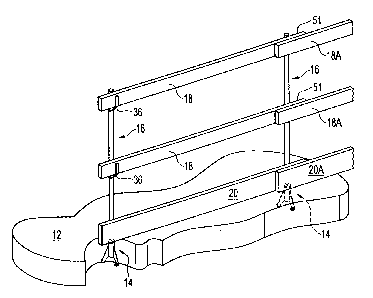
In Figure 1 ofthe accompanying drawings, there is shown a safety railing,
indicated generally
by reference 10, which is installed on a concrete floor 12. The safety railing
10 has post
sockets, of which only one is shown in Figure 1 and is indicated generally by
reference
numeral 14, posts indicated generally by reference numerals 16, and horizontal
rails 18
supported on the posts 16. A lowermost rail, commonly referred to in the
construction
industry as a "kick rail", is indicated by reference numeral 20 and supported
on the concrete
floor 12 by the posts 16.
One of the post supports 14 is illustrated in greater detail in Figures 2
through 4, and
comprises an open-topped cylindrical post socket 22, with a circular lid 24
for closing the
top of the cylindrical post socket 22.
The cylindrical post socket 22 is provided on a socket supports formed by
three legs or
support members in the form of flanges 26, which are equi-angularly spaced
apart around the
cylindrical post socket 22. These flanges 26 extend downwardly and laterally
outwardly of
CA 02528985 2005-12-06
-6-
the cylindrical post socket 22 from the outer cylindrical surface of the
cylindrical post socket
22.
Each of the flanges 26 terminates at its lower portion in a foot portion,
indicated generally
by reference numeral 28, extending laterally from the respective flange 25. In
the
embodiment of the post support 14 of Figures 2 through 3, each foot portion 28
has, at its
underside, a pair of spaced parallel rib-shaped projections forming downwardly
tapered
underside portions 30 of the foot portion 28. A vertical fastener opening 32
extends through
the foot portion 28, the opening 32 extending, at the bottom of the opening
32, between the
downwardly tapered underside portions 30.
The cylindrical post socket 22, the flanges 26, the foot portions 28 are
formed in one piece,
of plastic material, by molding. The hollow interior of the cylindrical post
socket 22 is
dimensioned to receive the lower end of one of the posts 16.
Figures 5 and 6 show one of the posts 16, which is formed from a length of
pipe 34, to which
a vertically spaced pair of a rail support brackets 36 and a toe kick bracket
38 are secured by
welding.
Figures 7 and 8 show one of the rail support brackets 36 in greater detail. As
shown in
Figure 8, the rail support bracket 36 comprises a lower portion formed by a
pair of spaced,
parallel triangular flanges 40, which are bridged by an intermediate portion
42. A circularly
curved edge 44 formed at one end of the intermediate portion 42, and vertical
edges 46 of
the flanges 40, fit snugly against and are welded to the outer surface of the
pipe 34 of the rail
16 and are connected to the pipe 34 by welding 47. At the end of the
intermediate portion
42 opposite from the circularly curved edge 44, an upturned flange 48 extends
vertically
upwardly from the intermediate portion 42.
CA 02528985 2006-02-06
-7-
The flange 48 is formed with a nail hole 49, through which a nail (not shown)
may, if
required, be driven into the rail 18 supported on the bracket 36 to secure
that rail 18 to the
support bracket 36. The flange 48 is also formed with a slot 51, which extends
to the top of
the flange 48 and which may, if required, removably receive a nail driven into
the rai118, so
that the rail 18 can be lifted from the bracket 36 if, for example, it is
desired to temporarily
remove the rail 36 to allow someone to pass through the railing 10.
As shown at the right-hand side of Figure 1, additional rails 18A may be
positioned so as to
overlap adjacent ends 51 of the rails 18 and also to overlap the flanges 48 at
the rail ends 51.
These additional rails are secured by nailing them to the rail ends 51.
The toe kick bracket 38, as shown in Figures 9 and 10, has a pair of side
walls 50, with an
intermediate portion 52 extending between the bottoms of the side walls 50,
and a vertical
plate 54. The intermediate portion 52 is formed with a circular opening 56,
which is
dimensioned to snugly receive therethrough the pipe 34 of the post 16.
The vertical plate 54 is formed with a rectangular cutout 58, which extends
vertically
downwardly from the top of the vertical plate 54. As shown in Figure 9, the
pipe 34 is
secured to the intermediate portion 52 by welding 59 around the circular
cutout 56, and to
the edges of the cutout 58 in the vertical plate 54 by welding 61.
The side walls 50, which project upwardly from the intermediate portion 52 at
opposite sides
of the circular opening 56, have vertical edges 60, which terminate at a
spacing above the
intermediate portion 52 and which, as shown in Figure 9, are also welded to
the pipe 34 by
welding 63. The spacings between these edges 60 and the plate 54 facilitate
the forming of
the side walls 50 perpendicular to the intermediate portion 52.
CA 02528985 2005-12-06
-8-
. r.
111C vc161ca1 iJlalc J'T 1J a13v 1v1111cu vv1111 apall vl llall llv1cJ JJ,
6111vug11 W111G11 lld11'J 111U1
shown) may be driven into the toe kick 20 to secure the toe kick 20 to the
corresponding post
34.
As will be readily apparent to those skilled in the art, the form of the rail
support brackets 36
and the toe kick brackets 38 may be varied. For example, the two side walls 40
of the rail
support bracket 36 may be replaced by a single triangular gusset (not shown)
welded to the
underside of the intermediate portion 42 and to the pipe 34. Also, the side
walls 50 of the toe
kick bracket 38 may be replaced by a single central gusset (not shown) welded
to the
underside of the intermediate portion 56 and to the pipe 34, the intermediate
portion having
a triangular or circularly curved shape.
As shown in Figure 1, another toe kick 20A may be installed in overlapping
relationship
relative to the toe kick 20, the toe kick 20A being nailed to the toe kick 20.
Figures 11 and 12 shows two stages in the construction of a building floor,
indicated
generally by reference numeral 62.
Before the casting of the concrete floor 62, the post sockets 14, only one of
which is shown
in Figure 11, are mounted at a predetermined spacing from one another on
concrete floor
formwork, which is shown broken-away in Figure 11 and indicated by reference
numeral 64.
The concrete floor formwork 64 is made of plywood, and the post support 14 is
temporarily
secured to the concrete floor formwork 64 by means of nails 66, which are
inserted through
the vertical openings 32 in the foot portions 28 of the flanges 26 and driven
into the plywood
of the concrete floor formwork 64.
When the required number of the post supports 14 have been mounted on and
secured to the
concrete floor formwork 64 in this way, with the lids 24 covering the open
tops of the post
supports 14, concrete is poured onto the concrete floor formwork 64 to the
level of the tops
CA 02528985 2005-12-06
-9-
of the lids 24. As this occurs, the concrete flows beneath the underside of
the cylindrical post
socket 22 of each post support 14, so that the concrete floor 62 extends
beneath the
cylindrical post socket 22.
When the concrete of the concrete floor 62 has sufficiently hardened, the
concrete floor
formwork 64 is removed to expose an undersurface 68 of the concrete floor 62.
In
accordance with conventional building construction practice, this undersurface
68 is then
ground to smoothen it. During this grinding operation, any ends of the nails
66, and any
parts of the downwardly tapered portions 32 of the foot portions 28 of the
flanges 26,
protruding from the undersurface 68 of the concrete floor 62 are also ground
and, thereby,
smoothened.
In the next step, and also in accordance with conventional building
construction practice, a
thin finish layer 70 of concrete is applied to the undersurface 68 of the
concrete floor 62, and
this finish layer 70 conceals any parts of the nails 66 and the foot portions
28 visible at the
undersurface 68.
The lids 24 are removed from the post supports 14 to allow the lower ends of
the posts 16
to be inserted into the cylindrical bodies 22, and the rails 18 and the toe
kick 20 are then
installed on the posts 16, as shown in Figure 1 to form the safety railing 10.
When the safety railing 10 is no longer required, the rails 18 and 18A, the
toe kicks 20 and
20A and the posts 16 are removed and, also in accordance with conventional
building
construction practice, a finish layout 72 of concrete is applied to the top of
the concrete floor
62. This finish layer 72 simultaneously fills the interior of the post sockets
22 and covers
and conceals the post supports 14 embedded in the concrete floor 62.
Figure 13 shows a post socket 114, which is a modification of the post support
14 of Figures
2 through 4. Instead of having the foot portions 28 having two downwardly
extending rib-
CA 02528985 2005-12-06
-10-
shaped portions 30, such as those shown in the post support 14, the post
socket 114 of Figure
13 has foot portions 28A each with only a single downwardly extending,
downwardly tapered
rib-shaped portion 130 at the underside of each lower portion 28A. This
replacement of the
pairs of downwardly tapering portions 30 by single downwardly tapering
portions 130
facilitates flow of the concrete beneath the foot portions 28A during the
casting of the
concrete floor 62.
It has also been found that the post support 14 or 114 can usefully be
employed in the
screeding of a concrete floor. For this purpose, two or more of the post
supports are mounted
on a formwork, e.g. the formwork 64 and a laser beam is directed across the
tops of these
post supports to ascertain whether they are level. If so, then the concrete
can be poured and
a length of lumber can them be positioned on the post supports and then used
to screed, i.e.
to level, the concrete.
The heights of the post supports determine the thickness of the concrete floor
62, and the
post supports 14 and 114 may therefore be produced in different sizes to
enable the casting
of floors of correspondingly different thicknesses.
While each of the post supports 14 and 114 is formed with three support
members or legs 26,
which are sufficient to provide stability, it would alternatively be possible
to use four or even
more legs, but that would require additional plastic material labor for
nailing and, therefore,
unnecessary expense. It would also be possible to provide each post socket 22
with a socket
support different from the above-described socket supports formed by the
support members
26, e.g. a socket support of cruciform cross-section.
As will be apparent to those skilled in the art, various modifications may be
made in the
above-described embodiment of the present invention within the scope of the
appended
claims.