Sélection de la langue

Search

Sommaire du brevet 2529165 

Énoncé de désistement de responsabilité concernant l'information provenant de tiers

Une partie des informations de ce site Web a été fournie par des sources externes. Le gouvernement du Canada n'assume aucune responsabilité concernant la précision, l'actualité ou la fiabilité des informations fournies par les sources externes. Les utilisateurs qui désirent employer cette information devraient consulter directement la source des informations. Le contenu fourni par les sources externes n'est pas assujetti aux exigences sur les langues officielles, la protection des renseignements personnels et l'accessibilité.

Disponibilité de l'Abrégé et des Revendications

L'apparition de différences dans le texte et l'image des Revendications et de l'Abrégé dépend du moment auquel le document est publié. Les textes des Revendications et de l'Abrégé sont affichés :

  • lorsque la demande peut être examinée par le public;
  • lorsque le brevet est émis (délivrance).
(12) Demande de brevet: (11) CA 2529165
(54) Titre français: SURFACE DE DECHARGE A MESURE POUR TRANSPORTEUR A ROULEAUX A TRANSMISSION A COURROIE
(54) Titre anglais: METERING DISCHARGE BED FOR BELT-DRIVEN ROLLER CONVEYOR
Statut: Réputée abandonnée et au-delà du délai pour le rétablissement - en attente de la réponse à l’avis de communication rejetée
Données bibliographiques
(51) Classification internationale des brevets (CIB):
  • B65G 47/31 (2006.01)
  • B65G 13/07 (2006.01)
  • B65G 15/24 (2006.01)
  • B65G 47/34 (2006.01)
(72) Inventeurs :
  • BAKER, TIMOTHY R. (Etats-Unis d'Amérique)
(73) Titulaires :
  • TGW-ERMANCO, INC.
(71) Demandeurs :
  • TGW-ERMANCO, INC. (Etats-Unis d'Amérique)
(74) Agent: OSLER, HOSKIN & HARCOURT LLP
(74) Co-agent:
(45) Délivré:
(22) Date de dépôt: 2005-12-06
(41) Mise à la disponibilité du public: 2006-07-07
Licence disponible: S.O.
Cédé au domaine public: S.O.
(25) Langue des documents déposés: Anglais

Traité de coopération en matière de brevets (PCT): Non

(30) Données de priorité de la demande:
Numéro de la demande Pays / territoire Date
60/642,206 (Etats-Unis d'Amérique) 2005-01-07

Abrégés

Abrégé anglais


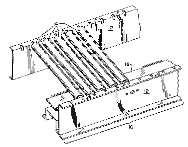
A metering discharge bed for a belt-driven roller
conveyor is provided by a second section of rollers positioned
downstream of a first section of rollers, the rollers being
carried for rotation between opposed side frames. The rollers
in the second section are of the same diameter as those in the
first section and include two driven rollers that define the
opposite ends of the second section. Each of the driven
rollers has a drive roller associated therewith which is
selectively engageable with the drive belt and has the same
diameter as the rollers in the first and second section. Each
of the drive rollers has a collar of a diameter greater than
that of the rollers in the first and second section, and is
linked to its driven roller by at least one belt trained about
the driven roller and the collar. Consequently, when the
drive rollers of the second section are engaged by the drive
belt, the driven rollers in the second section are driven at a
rotational speed greater than the rollers in the first section
that is proportional to a ratio of the diameter of the collar
to the diameter of the rollers.

Revendications

Note : Les revendications sont présentées dans la langue officielle dans laquelle elles ont été soumises.


-9-
CLAIMS
1. A discharge bed for use with a belt-driven roller
conveyor system comprising opposed side frames, a first
section of rollers carried for rotation between the opposed
side frames each roller in the first section being of a first
diameter, and an endless rotatable drive belt adapted to
contact the rollers in the first section so as to rotate the
first section of rollers at a first speed; the discharge bed
comprising:
a second section of rollers carried for rotation
between opposed side frames, the rollers in the second
section also being of the first diameter, the second
section of rollers comprising two driven rollers that
define opposite ends of the second section, each of the
driven rollers having a drive roller associated
therewith, the drive rollers being the first diameter and
selectively engageable with the drive belt, each drive
roller having a collar associated therewith of a second
diameter greater than the first diameter, each drive
roller being linked to its driven roller by at least one
belt trained about the driven roller and the collar
associated with the drive roller, whereby when the drive
rollers of the second section are engaged by the drive

-10-
belt the driven rollers in the second section are driven
at a rotational speed greater than the rollers in the
first section proportional to a ratio of the second
diameter to the first diameter.
2. The discharge bed of claim 1 further comprising a
third section of rollers intermediate the first section of
rollers and the second section of rollers, the rollers
comprising the second section also being of the first diameter
and carried for rotation between opposed side frames, the
third section of rollers comprising two driven rollers
defining opposite ends of the third section, each of the two
driven rollers of the third section having a drive roller
associated therewith of a third diameter less than the first
diameter that is selectively engageable with the drive belt,
each of the drive rollers for the third section being linked
to its driven roller by at least one belt trained about the
driven roller and the drive roller, whereby when the drive
rollers in the third section are engaged by the drive belt the
driven rollers in the third section are driven at a rotational
speed less than the rollers in the first section proportional
to the ratio of the third diameter to the first diameter.
3. The discharge bed of claim 1 in which the rollers of
the second section intermediate the driven rollers are slave
driven off the driven rollers of the second section.

-11-
4. The discharge bed of claim 2 or claim 3 in which the
rollers of the third section intermediate the driven rollers
are slave driven off the driven rollers of the third section.
5. The discharge bed of claim 1 wherein the second
section of rollers support at least one belt for supporting
items conveyed on the second section.
6. The discharge bed of claim 2 or claim 5 wherein the
rollers of the third section carry at least one belt for
supporting items conveyed on the third section.
7. The discharge bed of claim 2 wherein the drive
rollers of each of the second and third sections are moveable
from a first position in which the drive belt is spaced from
the drive rollers to a second position in which the drive
rollers are brought into contact with the drive belt.
8. The discharge bed of claim 7 further comprising
brake pads corresponding to each drive roller that are
supported by the side frames, the drive rollers contacting the
brake pads when in the first position.
9. A belt-driven roller conveyor system comprising:
opposed side frames;
a first section of rollers carried for rotation
between the opposed side frames each roller in the first
section being of a first diameter;

-12-
an endless rotatable drive belt adapted to contact the
rollers in the first section so as to rotate the first
section of rollers at a first speed; and
a second section of rollers carried for rotation
between opposed side frames, the rollers in the second
section also being of the first diameter, the- second
section of rollers comprising two driven rollers that
define opposite ends of the second section, each of the
driven rollers having a drive roller associated
therewith, the drive rollers being the first diameter and
selectively engageable with the drive belt, each drive
roller having a collar associated therewith of a second
diameter greater than the first diameter, each drive
roller being linked to its driven roller by at least one
belt trained about the driven roller and the collar
associated with the drive roller, whereby when the drive
rollers of the second section are engaged by the drive
belt the driven rollers in the second section are driven
at a rotational speed greater than the rollers in the
first section proportional to a ratio of the second
diameter to the first diameter.
10. The conveyor system of claim 9 further comprising a
third section of rollers intermediate the first section of
rollers and the second section of rollers, the rollers

-13-
comprising the second section also being of the first diameter
and carried for rotation between the opposed side frames, the
third section of rollers comprising two driven rollers
defining opposite ends of the third section, each of the two
driven rollers of the third section having a drive roller
associated therewith of a third diameter less than the first
diameter that is selectively engageable with the drive belt,
each of the drive rollers for the third section being linked
to its driven roller by at least one belt trained about the
driven roller and the drive roller, whereby when the drive
rollers in the third section are engaged by the drive belt the
driven rollers in the third section are driven at a rotational
speed less than the rollers in the first section proportional
to the ratio of the third diameter to the first diameter.
11. The conveyor system of claim 9 in which the rollers
of the second section intermediate the driven rollers are
slave driven off the driven rollers of the second section.
12. The conveyor system of claim 10 or claim 11 in which
the rollers of the third section intermediate the driven
rollers are slave driven off the driven rollers of the third
section.
13. The conveyor system of claim 9 wherein the second
section of rollers support at least one belt for supporting
items conveyed on the second section.

-14-
14. The conveyor system of claim 10 or claim 13 wherein
the rollers of the third section carry at least one belt for
supporting items conveyed on the third section.
15. The conveyor system of claim 10 wherein the drive
rollers of each of the second and third sections are moveable
from a first position in which the drive belt is spaced from
the drive rollers to a second position in which the drive
rollers are brought into contact with the drive belt.
16. The conveyor system of claim 15 further comprising
brake pads corresponding to each drive roller that are
supported by the side frames, the drive rollers contacting the
brake pads when in the first position.
17. A discharge bed for use with a belt-driven roller
conveyor system comprising opposed side frames, a first
section of rollers carried for rotation between the opposed
side frames each roller in the first section being of a first
diameter, and an endless rotatable drive belt adapted to
contact the rollers in the first section so as to rotate the
first section of rollers at a first speed; the discharge bed
comprising:
a second section of rollers carried for rotation
between opposed side frames, the rollers in the second
section also being of the first diameter, the second
section of rollers comprising at least one driven roller

-15-
having a drive roller associated therewith, the drive
roller being the first diameter and selectively
engageable with the drive belt, the drive roller having a
collar associated therewith of a second diameter greater
than the first diameter and being linked to its driven
roller by at least one belt trained about the driven
roller and the collar associated with the drive roller,
whereby when the drive roller of the second section is
engaged by the drive belt the driven roller in the second
section is driven at a rotational speed greater than the
rollers in the first section proportional to a ratio of
the second diameter to the first diameter.
18. The discharge bed of claim 17 further comprising a
third section of rollers intermediate the first section of
rollers and the second section of rollers, the rollers
comprising the second section also being of the first diameter
and carried for rotation between opposed side frames, the
third section of rollers comprising at least one driven
roller, the driven roller of the third section having a drive
roller associated therewith of a third diameter less than the
first diameter that is selectively engageable with the drive
belt, the drive roller for the third section being linked to
its driven roller by at least one belt trained about the
driven roller and the drive roller, whereby when the drive

-16-
rollers in the third section is engaged by the drive belt the
driven roller in the third section is driven at a rotational
speed less than the roller in the first section proportional
to the ratio of the third diameter to the first diameter.
19. The discharge bed of claim 17 in which the rollers
of the second section are slave driven off the driven roller
of the second section.
20. The discharge bed of claim 18 or claim 19 in which
the rollers of the third section are slave driven off the
driven roller of the third section.
21. The discharge bed of claim 17 wherein the second
section of rollers support at least one belt for supporting
items conveyed on the second section.
22. The discharge bed of claim 18 or claim 19 wherein
the rollers of the third section carry at least one belt for
supporting items conveyed on the third section.
23. The discharge bed of claim 18 wherein the drive
rollers of each of the second and third sections are moveable
from a first position in which the drive belt is spaced from
the drive rollers to a second position in which the drive
rollers are brought into contact with the drive belt.
24. The discharge bed of claim 23 further comprising
brake pads corresponding to each drive roller that are
supported by the side frames, the drive rollers contacting the

-17-
brake pads when in the first position.

Description

Note : Les descriptions sont présentées dans la langue officielle dans laquelle elles ont été soumises.


CA 02529165 2005-12-06
-1-
METERING DISCHARGE BED FOR
BELT-DRIVEN ROLLER CONVEYOR
BACKGROUND OF THE INVENTION
(0001] The present application relates to a metering or
index discharge bed for use with a belt-driven roller
conveyor.
[0002] With reference to Fig. 1 of the drawings, a
simplified section of a typical belt-driven roller conveyor,
generally designated 10, is shown. The conveyor section 10
includes a pair of parallel side frame members 12 that support
a plurality of rollers 14. The rollers 14 are driven from
underneath by frictional engagement with a drive belt 16. The
drive belt 16 is supported on its underside by a series of
guide rollers 18 (best seen in Figs. 4 and 5) spaced along the
length of the conveyor 10.
10003] Typically, when off-loading a product from a
conveyor onto, e.g., a pallet, a specific number of items need
to be discharged for each pallet. Oftentimes, after the items
have been accumulated on the conveyor prior to discharging,
there is inadequate spacing between the items to permit them
to be counted by, e.g., a photoeye. Specifically, in order

CA 02529165 2005-12-06
-2-
for the conveyed items to be counted, they must be adequately
separated. Additionally, after the predetermined number of
items have been discharged, the discharge bed needs to be
substantially instantaneously stopped while further product is
being accumulated.
[0004] Accordingly, it is an object of the present
invention to provide a discharge bed for a belt-driven roller
conveyor that operates to properly space conveyed articles.
SUMMARY OF THE INVENTION
L0005~ This object, as well as others that will become
apparent upon reference to the following detailed description
and accompanying drawings, is accomplished by providing a
belt-driven roller conveyor in which a first section of
rollers are carried for rotation between opposed side frames
that are driven by an endless rotatable belt adapted to
contact the rollers so as to rotate the first section of
rollers at a first speed. This comprises a typical belt-driven
roller conveyor.
[00061 In keeping with one aspect of the invention, a
second section of rollers is positioned downstream of the
first section of rollers that are also carried for rotation
between the opposed side frames. The rollers in the second
section are of the same diameter as those in the first
section. In addition, the second section of rollers includes

CA 02529165 2005-12-06
-3-
two driven rollers that preferably define the opposite ends of
the second section. Each of the driven rollers has a drive
roller associated therewith. The drive roller has the same
diameter as the rollers in the first and second section and is
selectively engageable with the drive belt. Each of the drive
rollers has a collar of a diameter greater than that of the
rollers in the first and second section, and each drive roller
is linked to its driven roller by at least one belt trained
about the driven roller and the collar. Consequently, when
the drive rollers of the second section are engaged by the
drive belt, the driven rollers in the second section are
driven at a rotational speed greater than the rollers in the
first section that is proportional to a ratio of the diameter
of the collar to the diameter of the rollers.
[0007) Optionally, in keeping with another aspect of the
invention, the conveyor system may have a third section of
rollers intermediate the first section and the second section.
The third section of rollers includes two driven rollers
preferably defining opposite ends of the third section, with
each of the driven rollers for the third section having a
drive roller of a diameter less than the diameter associated
with the rollers comprising the third section, the drive
roller being selectively engageable with the drive belt. Each
of the drive rollers for the third section is linked to its

CA 02529165 2005-12-06
-4-
driven roller by at least one belt trained about the driven
roller and the drive roller. Consequently, when the drive
rollers in the third section are engaged by the drive belt,
the driven rollers in the third section are driven at a
rotational speed less than the rollers in the first section
that is proportional to the ratio of the diameter of the third
section drive rollers to the rollers of the first section.
BRIEF DESCRIPTION OF THE FIGURES OF THE DRAWINGS
(0008] Fig. 1 is a partial perspective view of a segment of
a conventional belt-driven roller conveyor.
(0009] Fig. 2 is a perspective view of a discharge bed
according to the present invention, with the conventional
roller conveyor being shown in dotted lines.
(00010) Fig. 3 is a side view of a conveyor system of Fig.
2.
(00011] Fig. 4 is a top view of a conveyor system of Fig. 2,
with various of the rollers removed to show detail.
DETAILED DESCRIPTION OF THE PREFERRED EMBODIMENT
(00012] The present invention provides for metered discharge
of accumulated articles in the context of a belt-driven roller
conveyor. With reference to Figs. 2-4, a conveyor system is
shown including a belt-driven section 10 conventional in the
art as described above, and a first section downstream thereof
comprising a preferred embodiment of a discharge bed,

CA 02529165 2005-12-06
_5_
generally designated 20. The discharge bed 20 has a driven
roller 22 preferably at each end thereof, about~which a belt
24 is entrained for conveying articles on the discharge bed.
While a single belt is shown, a plurality of narrow belts
could be used, depending upon the nature of the items being
conveyed, without departing from the invention. A plurality
of rollers 26 are disposed between the two driven rollers 22.
These intermediate rollers 26 freely rotate and are preferably
slave-driven off the driven rollers 22. Underlying each
driven roller 22 is a drive roller 28 having generally the
same diameter as the driven rollers 14, 26 in the remainder of --
the conveyor, the drive rollers 28 being engaged by the same
drive belt 16 that powers the conveyor rollers 14. A belt 30
connects the drive rollers 28 for the discharge bed to the
driven rollers 22 in order to rotate the same.
[00013 In keeping with the invention, the drive rollers
include a pulley or collar 32 that is oversized with respect
to the driven roller 22 overlying it, in order to increase the
speed of the conveying belt 24 in the discharge bed relative
to section 10 of the conveyor. The pulley 32 receives the
belt 30 connecting the driven rollers 22 of the discharge bed
to their respective drive roller 28. In the illustrated
embodiment, the pulley 32 has two grooves, corresponding to
two grooves in the driven roller 22 of the discharge bed, and

CA 02529165 2005-12-06
-6-
a pair of round belts 30 (typically made of urethane) connect
the driven roller 22 to its associated drive roller 28. In the
preferred embodiment, the pulley 32 on the drive roller 28 is
approximately twice the diameter of the drive roller. Thus,
the driven roller 22 will rotate at approximately twice the
speed as both the drive rollers 28, as well as twice the speed
of the rollers 14 on the section 10 of the conveyor.
Consequently, the belts 24 in the discharge bed will move
conveyed items at twice the speed that they are traveling when
they leave section 10 of the conveyor.
[00014) As best seen in Figs. 2-4, each drive roller 28 for
the discharge bed section 20 is moveable into and out of
engagement with the drive belt 16 for the conveyor by a
double-acting actuator 34 mounted externally to the frame
members 12 to activate the discharge bed. The actuator 34 is
preferably a hydraulic or pneumatic cylinder, but may be,
e.g., an electro-mechanical device without departing from the
present invention. Specifically, one end of the axle of each
of the drive rollers 28 is journaled in a lever 36 pivotably
secured to the side frame 12 and to which the piston rod of
each actuator 34 is connected. When the actuators 34 are
activated so as to bring the drive rollers 28 into engagement
with the drive belt 16, the axles of the drive rollers will be
perpendicular to the side frames 12.

CA 02529165 2005-12-06
_7_
I00015I A braking device is preferably incorporated into the
system so that rotation of the drive rollers can be arrested
when the drive belt is disengaged. To this end, when the
drive roller 28 is moved out of engagement with the drive
belt, it is moved into engagement with a brake pad to halt the
movement of the belts 24.
(00016 In certain circumstances, a two-stage metering
discharge bed may be required to insure proper spacing of the
conveyed articles. As shown in Figs 2-4, a second stage 40 is
located intermediate the stage 20 and section 10 of the
conveyor upstream thereof. Like stage 20 of the discharge
bed, stage 40 utilizes a single wide conveyor belt 42, but
could alternatively utilize a plurality of narrow belts 24 as
described above. In other aspects, stage 40 of the discharge
bed is substantially similar to the stage 20, except for the
difference noted below, and thus the same reference numerals
will be used as appropriate.
[000171 In stage 40 of the discharge bed, the conveyor belt
42 moves at a slower speed than the conveyed products are
moving when they enter the first stage 40. This essentially
closes any gaps between the conveyed articles before they
enter the second stage 20 of the discharge bed. The use of
the two stages 20, 40 helps to insure uniform spacing of the
conveyed articles as they exit the second stage 20. To this

CA 02529165 2005-12-06
_g_
end, the first stage 40 has drive rollers 44 corresponding to
the drive rollers 28 of the discharge bed 20, except that they
have a smaller diameter than the driven rollers 14 in section
of the conveyor, thus decreasing the speed of its
associated conveyor belt 44 relative to the driven rollers 14.
The drive rollers 44 are moved into and out of engagement with
the drive belt by double-acting actuators 34 in the same
manner as described above, and a braking device may be
employed to arrest the rotation of the drive rollers 44 , also
as described above.
[00018) Thus, a metering discharge bed for a belt-driven
roller conveyor has been provided that meets the objects of
the present invention. While the invention has been described
in terms of a preferred embodiment, there is not intent to
limit it to the same. For example, in the preferred
embodiment, each of the two metering discharge beds is
described as having a driven roller at each end. However, it
is conceivable that each of the discharge beds could utilize a
single driven roller off of which all the other rollers are
slave-driven. Thus, it is intended that the invention be
defined by the scope of the appended claims.

Dessin représentatif
Une figure unique qui représente un dessin illustrant l'invention.
États administratifs

2024-08-01 : Dans le cadre de la transition vers les Brevets de nouvelle génération (BNG), la base de données sur les brevets canadiens (BDBC) contient désormais un Historique d'événement plus détaillé, qui reproduit le Journal des événements de notre nouvelle solution interne.

Veuillez noter que les événements débutant par « Inactive : » se réfèrent à des événements qui ne sont plus utilisés dans notre nouvelle solution interne.

Pour une meilleure compréhension de l'état de la demande ou brevet qui figure sur cette page, la rubrique Mise en garde , et les descriptions de Brevet , Historique d'événement , Taxes périodiques et Historique des paiements devraient être consultées.

Historique d'événement

Description Date
Le délai pour l'annulation est expiré 2010-12-06
Demande non rétablie avant l'échéance 2010-12-06
Réputée abandonnée - omission de répondre à un avis sur les taxes pour le maintien en état 2009-12-07
Inactive : Demandeur supprimé 2006-09-26
Lettre envoyée 2006-09-26
Demande de correction du demandeur reçue 2006-08-03
Inactive : Transfert individuel 2006-08-03
Demande publiée (accessible au public) 2006-07-07
Inactive : Page couverture publiée 2006-07-06
Inactive : CIB en 1re position 2006-06-20
Inactive : CIB attribuée 2006-06-20
Inactive : Lettre de courtoisie - Preuve 2006-01-24
Inactive : Certificat de dépôt - Sans RE (Anglais) 2006-01-23
Exigences de dépôt - jugé conforme 2006-01-23
Demande reçue - nationale ordinaire 2006-01-20

Historique d'abandonnement

Date d'abandonnement Raison Date de rétablissement
2009-12-07

Taxes périodiques

Le dernier paiement a été reçu le 2008-12-08

Avis : Si le paiement en totalité n'a pas été reçu au plus tard à la date indiquée, une taxe supplémentaire peut être imposée, soit une des taxes suivantes :

  • taxe de rétablissement ;
  • taxe pour paiement en souffrance ; ou
  • taxe additionnelle pour le renversement d'une péremption réputée.

Les taxes sur les brevets sont ajustées au 1er janvier de chaque année. Les montants ci-dessus sont les montants actuels s'ils sont reçus au plus tard le 31 décembre de l'année en cours.
Veuillez vous référer à la page web des taxes sur les brevets de l'OPIC pour voir tous les montants actuels des taxes.

Historique des taxes

Type de taxes Anniversaire Échéance Date payée
Taxe pour le dépôt - générale 2005-12-06
Enregistrement d'un document 2006-08-03
TM (demande, 2e anniv.) - générale 02 2007-12-06 2007-11-20
TM (demande, 3e anniv.) - générale 03 2008-12-08 2008-12-08
Titulaires au dossier

Les titulaires actuels et antérieures au dossier sont affichés en ordre alphabétique.

Titulaires actuels au dossier
TGW-ERMANCO, INC.
Titulaires antérieures au dossier
TIMOTHY R. BAKER
Les propriétaires antérieurs qui ne figurent pas dans la liste des « Propriétaires au dossier » apparaîtront dans d'autres documents au dossier.
Documents

Pour visionner les fichiers sélectionnés, entrer le code reCAPTCHA :


Pour visualiser une image, cliquer sur un lien dans la colonne description du document. Pour télécharger l'image (les images), cliquer l'une ou plusieurs cases à cocher dans la première colonne et ensuite cliquer sur le bouton "Télécharger sélection en format PDF (archive Zip)" ou le bouton "Télécharger sélection (en un fichier PDF fusionné)".

Liste des documents de brevet publiés et non publiés sur la BDBC .

Si vous avez des difficultés à accéder au contenu, veuillez communiquer avec le Centre de services à la clientèle au 1-866-997-1936, ou envoyer un courriel au Centre de service à la clientèle de l'OPIC.


Description du
Document 
Date
(aaaa-mm-jj) 
Nombre de pages   Taille de l'image (Ko) 
Description 2005-12-05 8 259
Abrégé 2005-12-05 1 27
Revendications 2005-12-05 9 256
Dessins 2005-12-05 3 142
Dessin représentatif 2006-06-11 1 24
Certificat de dépôt (anglais) 2006-01-22 1 157
Courtoisie - Certificat d'enregistrement (document(s) connexe(s)) 2006-09-25 1 105
Rappel de taxe de maintien due 2007-08-06 1 112
Courtoisie - Lettre d'abandon (taxe de maintien en état) 2010-01-31 1 171
Rappel - requête d'examen 2010-08-08 1 120
Correspondance 2006-01-22 1 26
Correspondance 2006-08-02 3 102
Taxes 2008-12-07 1 45