Note : Les descriptions sont présentées dans la langue officielle dans laquelle elles ont été soumises.
CA 02532167 2011-06-20
63293-4053
- 1 -
SYSTEM AND METHOD FOR DRILLING USING A
MODULATED JET STREAM
The present invention relates to a system for making
a hole in an object, more particularly for making a hole
in a subterranean earth formation. in particular, the
system comprises jet means for generating an abrasive jet
of a mixture containing a fluid and a quantity of
abrasive particles and for blasting the abrasive jet with
an erosive power into impingement with the object in an
impingement area, thereby eroding the object in the
impingement area.
The invention also relates to a method of making a
hole in an object, more particularly for making a hole in
a subterranean earth formation. In particular, the method
comprises steps of generating an abrasive jet of a
mixture containing a fluid and a quantity of abrasive
particles and for blasting the abrasive jet with an
erosive power into impingement with the object.
In US patent 5,944,123 a drilling method is described
involving the rotation of a drilling member, whereby
drilling fluid is supplied to the drilling member to
issue therefrom via an orifice provided therein. Off axis
advance of the drilling member is achieved by modulating
the rotational s-1-Deed of the drilling member as it
rotates.
Due to increasing friction with the bore hole wall at
greater depths, the directional stability of this
arrangement is expected to reduce when drilling a bore
hole at relatively great depth, such as is generally
required for drilling of a well for production of mineral
hydrocarbons.
In accordance with the present invention there is
provided a system for making a hole in an object, the
CA 02532167 2006-01-05
WO 2005/005767 PCT/EP2004/051426
- 2 -
system comprising jet means for generating an abrasive
jet of a mixture containing a fluid and a quantity of
abrasive particles and for blasting the abrasive jet with
an erosive power into impingement with the object in an
impingement area, thereby eroding the object in the
impingement area, the system further comprising scanning
means for moving the impingement area along a selected
trajectory in the hole, and modulation means for
modulating the erosive power of the abrasive jet while
the impingement area is being moved along the selected
trajectory.
There is also provided a method of making a hole in
an object, the method comprising steps of
- generating an abrasive jet of a mixture containing a
fluid and a quantity of abrasive particles;
- blasting the abrasive jet with an erosive power into
impingement with the object in an impingement area,
thereby eroding the object in the impingement area;
- moving the impingement area along a selected
trajectory in the hole; and
- modulating the erosive power of the abrasive jet
while the impingement area is being moved.
By modulating the erosive power of the abrasive jet
while the impingement area is being moved, the amount of
erosion caused by one abrasive jet in each impingement
area along the selected trajectory can be varied.
Herewith directional control is achieved.
A curved hole can be drilled by eroding more of the
formation in a selected impingement area on one side of
the hole than in another selected area on an azimuthally
opposite side of the hole. A straight hole can be drilled
by evenly eroding the formation in all areas on the
trajectory.
In particular at greater depths, a system for making
a hole in the earth formation can be disturbed by
CA 02532167 2006-01-05
WO 2005/005767 PCT/EP2004/051426
- 3 -
friction between the drilling arrangement and the bore
hole wall surrounding the drilling arrangement. The
friction causes frictional forces acting on the drilling
system, which forces depend on movement of the system in
the hole. When the directional control relies on the
modulation of the rate of movement of the drilling
system, the mentioned friction therefore disturbs the
directional stability of the system.
An advantage of modulating the erosive power of the
abrasive jet is that thereby the material removal rate
from the object is modulated while the direct mechanical
contact between the drilling tool and the bore hole wall
does not have to change.
The erosive power of the abrasive jet can be
modulated by modulating the power vested in kinetic
energy of the abrasive particles present in the abrasive
jet. This can be done by modulating the mass flow rate of
the abrasive particles in the abrasive jet, for instance
by modulating the quantity of the abrasive particles in
the abrasive jet, or by modulating the velocity of the
abrasive particles in the abrasive jet, which can be done
for instance by modulating an acceleration pressure drop
of the fluid in the jet means, or by combining these.
Preferably, the modulation means are coupled to
modulation control means arranged to control the
modulation means such that the erosive power is modulated
in relation with the position of the impingement area on
the selected trajectory. This way, the modulation can be
arranged such that the erosive power is be increased when
the abrasive jet is impinging the formation where more
erosion is required, and, vice versa, the erosive power
can be decreased when the abrasive jet is impinging the
formation where less erosion is required.
CA 02532167 2006-01-05
WO 2005/005767 PCT/EP2004/051426
4 -
The invention will now be illustrated by way of
example, with reference to the accompanying drawing
wherein
Fig. 1. schematically shows a cross section of a
system for making a hole in a subterranean earth
formation in accordance with the invention;
Fig. 2. schematically shows a cross section of part
of a preferred excavation tool for the system of Fig. 1;
Fig. 3 schematically shows a surface map of a magnet
surface arrangement for use in the preferred excavation
tool of Fig. 2; and
Fig. 4 schematically shows an example of a system for
making a hole in a subterranean earth formation including
a down hole power system.
In the figures, like parts carry identical reference
numerals.
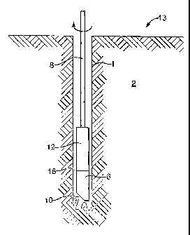
Fig. 1 schematically shows a system for making a
hole 1 in an object in the form of a subterranean earth
formation 2, in particular a hole for the manufacture of
a well for production of mineral hydrocarbons. The system
comprises an excavating tool 6 mounted on a lower end of
a drill string 8 that is inserted from the surface 13
into the hole 1. The drill string 8 is provided with a
longitudinal passage for transporting a drilling fluid to
the excavating tool 6. The e_cavating tool 6 comprises
jet means (not shown) arranged to generate an abrasive
jet 10 in a jetting direction into impingement with the
earth formation 2 in an impingement area. The abrasive
jet has a certain erosive power that can be modulated.
The system further comprises scanning means (not
shown) arranged to move the abrasive jet along the
formation, thereby moving the impingement area along a
trajectory. In the system of Fig. 1, the scanning means
is provided in the form of rotary means (schematically
represented by the arrow) for rotating the abrasive jet
CA 02532167 2006-01-05
WO 2005/005767 PCT/EP2004/051426
- 5 -
in the hole about a rotary axis, which rotary axis
essentially coincides with a longitudinal direction of
the hole. Since the impingement area is located eccentric
with respect to the rotary axis, rotating the abrasive
jet in the hole results in the jet and the impingement
area moving along an essentially circular trajectory in
the hole. Preferably, the eccentric impingement area
overlaps with the centre of rotation, so that also the
middle of the bore hole is subject to the erosive power
of the abrasive jet.
The drill string 8 is also provided with a controller
unit 12, such that the controller unit is located inside
the hole. Alternatively, the controller unit can be
positioned at the surface 13. The controller unit 12 can
house equipment such as modulation means to modulate the
erosive power of the abrasive jet 10 impinging the
formation 2. Modulating the erosive power includes
controlling the erosive power.
In operation, the system works as follows. A stream
of drilling fluid is pumped by a suitable pump (not
shown) through the longitudinal passage of the drill
string 8. Part or all of the drilling fluid is led to the
jet means where an abrasive jet 10 is generated. The
abrasive jet is blasted into impingement with the
formation. The formation is eroded in the impingement
area as a result of the abrasive jet 10 impinging the
formation 2.
Simultaneously, the abrasive jet is rotated about the
rotary axis. Thus, the impingement area is moved along a
circular trajectory in the hole so that the formation can
be eroded at all azimuths. By modulating the erosive
power of the abrasive jet a high degree of directional
control can be achieved.
By keeping the erosive power of the abrasive jet
constant, the formation is eroded evenly on all sides of
CA 02532167 2006-01-05
WO 2005/005767 PCT/EP2004/051426
6 -
the hole and consequently the hole is excavated straight.
Nevertheless, distortions in the rotating of the
excavation tool, or variations in rock formation
properties in the hole region, or other causes may result
in uneven erosion in the hole. A directional correction
may be required by modulating the erosive power to
compensating for the unintentional uneven erosion. The
erosive power of the abrasive jet can also be modulated
in order to deliberately excavate a curved hole.
When the abrasive jet is oriented to impinge the
formation in an area that requires more erosion in order
to establish the directional correction, the erosive
power of the abrasive jet can be periodically increased
resulting in a higher erosion rate in that area.
Alternatively, or in combination, the erosive power of
the abrasive jet can be reduced when the abrasive jet is
oriented to impinge the formation in an area that
requires less erosion.
It is thus preferred that the modulation means
comprises modulation control means arranged to control
the modulation means such that the erosive power of the
abrasive jet is modulated in relation with the position
of the impingement area on the selected trajectory.
In order to establish the position of the impingement
area, the system can be provided with a positional
sensor, for instance a measurement while drilling sensor,
for providing a signal indicative of the position of the
abrasive jet. In order to establish the current drilling
direction through the formation, the system can be
provided with a navigational sensor, for instance a
measurement while drilling sensor, for providing a signal
indicative of the direction under which the making of the
hole in the earth formation progresses.
Such a navigational sensor can be provided in the
form of one of or a combination of a directional sensor
CA 02532167 2006-01-05
WO 2005/005767 PCT/EP2004/051426
7 -
providing a signal indicative of the direction of the
device relative to a reference vector; a positional
sensor providing a signal indicative of one or more
positional coordinates relative to a reference point; a
formation density sensor providing information on a
distance to a change of formation type or formation
content nearby; or any other suitable sensor.
The mechanical forces on the drilling system that is
based on abrasive jetting are much smaller than is the
case for systems based on mechanical rock removal. This
has the advantage that the sensors can be located very
close to the excavating tool, making early and accurate
signal communication possible to the modulation control
means. The sensors can for instance be provided in the
same chamber as the modulation control means.
Alternatively, the position and and/or the direction
of progress through the formation of the abrasive jet can
be determined on the basis of parameters available on the
surface 13, including torque on the drill string 8 and
azimuthal position of the drill string 8, and axial
position and velocity of the drill string 8.
A decision to change or correct drilling direction
may also be taken via the operator of the directional
system at surface. In case of the signal originating from
a down-hole measurement while drilling sensor, a f n.ud-
pulse telemetry system or any other suitable data
transfer system can be employed to transfer the data to
the surface. Via similar means of data transfer a control
signal can be sent to the down hole control means
triggering a series of control actions required for the
desired direction drilling correction.
A thruster (not shown) is advantageously provided for
pressing the abrasive jetting system upon the bottom of
the hole 1. Best results are obtained when the pressing
force is not much higher than what is required to keep
CA 02532167 2006-01-05
WO 2005/005767 PCT/EP2004/051426
8 -
the excavating tool 6 at the bottom, in order to avoid
unnecessary wear on the excavating tool 6, bending of the
system, and loss of directional control. Thus, the
pressing force is preferably just sufficient to
counteract the axial recoil force of the abrasive jet and
the friction forces in the thruster and between the
abrasive jet system and the hole wall. Typically, the
pressing force is well below 10 kN.
A suitable abrasive jet comprises a mixture
containing a fluid, such as the drilling fluid, and a
certain controlled quantity of abrasive particles. The
erosive power of the jet correlates with the total power
vested in the abrasive particles entrained in the
mixture. This depends on the mass flow rate of abrasive
particles and on the square of the velocity of the
abrasive particles.
Thus, one way of modulating the erosive power of the
abrasive jet is by modulating the velocity of the
abrasive particles. When the abrasive jet is generated in
jet means comprising an acceleration nozzle, the velocity
of the 'fluid is driven by a pressure drop over a flow
restriction. The square of the velocity of the fluid
accelerated over a flow restriction is ideally equal to
two times the pressure drop over the density of the
fluid. Since the abrasive particles are entrained in the
fluid, the erosive power of the abrasive jet is
proportional to the pressure drop.
Another way of modulating the erosive power of the
abrasive jet is by modulating the mass flow rate of the
abrasive particles in the abrasive jet. This can most
advantageously be achieved by modulating the quantity of
abrasive particles in the mixture. When the quantity of
similar particles is higher, the total erosive power of
the abrasive jet increases in that more of the formation
will be eroded. Modulation of the quantity of abrasive
CA 02532167 2006-01-05
WO 2005/005767 PCT/EP2004/051426
9 -
particles in the mixture does not influence the
mechanical contact forces between the drilling system and
the formation.
Still referring to Fig. 1, the abrasive particles
will be entrained in a return stream of drilling fluid
through the excavated hole, running for instance through
an annular space 16 between the hole 1 and the drilling
system (6, 12, 8) .
In order to reduce the concentration of abrasive
particles to be transported all the way back to the
surface, it is preferred to provide the drilling system,
preferably the excavation tool 6, with recirculation
means arranged to recirculate at least a part of the
abrasive particles from the return stream down stream
impingement with the formation back into the abrasive jet
10 again. The abrasive particles to be recirculated can
be mixed with the fresh stream of drilling fluid, for
instance in a mixing chamber to which both the fresh
stream of drilling fluid and the recirculated abrasive
particles are admitted.
The quantity of the abrasive particles in the mixture
can be modulated by modulating the rate at which the
abrasive particles are recirculated to the mixing
chamber.
Fig. 2 schematically shows a preferred embodiment of
an excavating tool 6 with recirculation capability,
suitable for use in the system of Fig. 1 when applying
abrasive particles containing a magnetisable material,
such as for instance steel shot or steel grit.
The preferred excavating tool 6 is provided with a
longitudinal drilling fluid passage 11, which is at one
end thereof in fluid communication with the drilling
fluid channel provided in the drill string 8 and at the
other end thereof in fluid communication with jet means.
The jet means comprises a mixing chamber 9 that is
CA 02532167 2006-01-05
WO 2005/005767 PCT/EP2004/051426
- 10 -
connected to the drilling fluid passage 11 via a first
inlet, here provided in the form of drilling fluid
inlet 3.
The mixing chamber 9 is also in fluid communication
with a second inlet, provided here in the form of an
inlet 4 for abrasive particles, and with a mixing
nozzle 5 leading to a nozzle arranged to jet a stream of
drilling fluid and abrasive particles against the earth
formation during excavating the hole 1 in the
subterranean earth formation 2.
The jet means is also provided with a piece of
magnetic material 14 on the side of the mixing chamber 9
that is opposite from the abrasive particle inlet 4, but
this is optional.
The mixing nozzle 5 is arranged above an optional
foot part 19, and is inclined relative to the
longitudinal direction of the system at an inclination
angle of 15-30 relative to the rotary axis, but other
angles can be used. Preferably the inclination angle is
about 21 , which is optimal for abrasively eroding the
bottom of the bore hole by axially rotating the complete
tool inside the bore hole. The mixing chamber 9 and
mixing nozzle 5 are aligned with an outlet nozzle under
the same angle, in order to achieve optimal acceleration
of the abrasive particles.
The drilling fluid passage 11 is arranged to bypass a
device for transporting magnetic particles, which device
is included in the excavating tool 6 as part of the
recirculation system for the magnetic abrasive particles.
The device includes a support member in the form of a
slightly tapered sleeve 15 for providing a support
surface extending around a conveyor means in the form of
an essentially cylindrically shaped elongate magnet 7.
The magnet 7 generates a magnetic field for retaining the
magnetic particles on the support surface 15.
CA 02532167 2006-01-05
WO 2005/005767 PCT/EP2004/051426
- 11 -
The drilling fluid passage 11 is fixedly arranged
relative to the support surface 15 and the mixing
chamber 9. The drilling fluid passage 11 has a lower end
arranged near the inlet 4 for abrasive particles. In the
present embodiment the drilling fluid passage 11 is
formed inside a ridge in the axial direction which ridge
is in protruding contact with the support surface 15. The
drilling fluid passage 11 may alternatively be arranged
freestanding from the support surface in a manner similar
to that shown and described in International Publication
WO 02/34653 with reference to Fig. 4 therein, or in a
off-axial direction. The inlet 4 for abrasive particles
is located at the lower end of the ridge.
The cylindrical magnet 7 is formed of eight smaller
magnets 7a to 7h stacked together. A different number of
smaller magnets can also be used. Each magnet 7a to 7h
has diametrically opposed N and S poles, and the magnets
are stacked in a manner that two essentially helical
diametrically opposing bands are each formed by the N and
S poles.
For the purpose of this specification, a magnetic
pole is an area on the magnet surface or on the support
surface where magnetic field lines cross the magnet
surface or the support surface thereby appearing as an
area of source or sink for magnetic field lines.
Directly adjacent to the diametrically opposing bands
formed by the poles, helical recesses are provided for
achieving helical bands having lower magnetic
permeability than the helical bands including the poles.
Due to the higher magnetic permeability of the magnet
material than the less magnet material that fills up the
recesses (a gas, a fluid, or a solid) the internal
magnetic field lines predominantly follow the material of
the magnet rather than the material contained in the
recess. Thus, there exists a strong gradient zone between
CA 02532167 2006-01-05
WO 2005/005767 PCT/EP2004/051426
- 12 -
the bands containing the poles and the recesses. Instead
of the recesses containing a gas, fluid or solid, there
can be vacuum in the grooves.
Preferably, the recess reaches a depth with respect
to the cylindrical circumference of the magnet that is
similar as or greater than the distance between the gap
between the magnetic surface in the first band and the
support surface.
The magnet 7 has a central longitudinal shaft 18 and
is rotatable relative to the sleeve 15 and about the
central longitudinal shaft 18. Drive means, of which more
details will be given below, are provided to drive
shaft 18 and thereby rotate the magnet 7.
A short tapered section 21 is provided at the lower
end of magnet 7. The support surface on sleeve 15 is
provided with a corresponding conical taper in a manner
that the inlet 4 for abrasive particles provides fluid
communication between the support surface 15 surrounding
the tapered section 21 and the mixing chamber 9. The
conical taper is best based on the same angle as the
above-discussed angle of the mixing chamber 9 and mixing
nozzle 5.
The magnet 7 is shown in more detail in Fig. 3, in a
cross sectional view (Fig. 3a), a longitudinal view
(Fig. 3b) of a lower part of the magnet, and a
representation wherein the cylindrical surface is
unrolled flat in the plane of the paper (Fig. 3c).
The region of reduced magnetic permeability is
provided in the form of a helical recess 26 in the outer
surface of the magnet 7 adjacent to the poles. Fig. 3a
shows circular contours 24 around the diametrically
opposing poles, connected by essentially straight
contours 25. The straight contours correspond with the
recess 26 and the circular contours with the parts of the
magnet containing the poles.
CA 02532167 2006-01-05
WO 2005/005767 PCT/EP2004/051426
- 13 -
The slanted phantom lines in Fig. 3b indicate the
transition between the circular contours and the
essentially straight contours.
In Fig. 3c, vertically is set out the height of the
magnet, which is divided in smaller magnets 7a to 7h, and
horizontally the surface at all azimuths between 0 and
360 is visible. As can be seen, the smaller magnets 7a
to 7h are arranged such that their individual poles align
in two helical bands, in the order of NSSNNSSN or
SNNSSNNS. The angle 0 of the helical recess 26 with the
plane perpendicular to the shaft 18 is 53 .
In operation, the preferred excavating tool of Fig. 2
works as follows. The tool is connected to the lower end
of the drill string 8 that is inserted from the
surface 13 into the borehole. A stream of drilling fluid
is pumped by a suitable pump (not shown) at surface, via
the drilling fluid channel of the drill string 8 and the
fluid passage 11 into the mixing chamber 9. During
pumping, the stream is provided with a small amount of
abrasive particles suitable in the form of steel shot.
The inlet 3 is arranged with a flow restriction, over
which a pressure drop is present driving the acceleration
of the drilling fluid.
The stream flows from the mixing chamber 9 via mixing
nozzle 5 and is thereby jetted against the borehole
bottom. Simultaneously, the drill string 8 is rotated in
the way described above. The return stream of fluid and
abrasive particles flows from the borehole bottom through
the annulus 16 in the bore hole in a direction back to
the surface. Thereby the return stream passes along the
sleeve 15. The magnet 7 induces a magnetic field
extending to and beyond the outer surface of the
sleeve 15. As the stream passes along the sleeve 15, the
abrasive particles in the stream are separated out from
the stream by the magnetic forces from the magnet 7 which
CA 02532167 2006-01-05
WO 2005/005767 PCT/EP2004/051426
- 14 -
attract the particles onto the outer surface of the
sleeve 15.
The stream of drilling fluid, which is now
substantially free from abrasive magnetic particles,
flows further through the bore hole to the pump at
surface and is re-circulated through the drill string
after removal of the drill cuttings.
The magnetic particles retained on the support
surface 15 are attracted towards the band having the
highest magnetic field. Simultaneously with pumping of
the stream of drilling fluid, the magnet 7 is rotated
about its shaft 18 in a direction of rotation that is
opposite to the sense of the helical band. Due to
rotation of the magnet 7, the presence of the gradient
zone causes a force on the magnetic particles in a
direction perpendicular to the gradient zone, which has a
downward component, thereby forcing the particles to
follow a helically downward movement towards the inlet 4.
In this way, the magnet 7 functions not only as a
separator of abrasive particles from the return stream,
but also as a conveyor means in that movement of the
magnet induces transport of the abrasive particles.
As the particles arrive at the inlet 4, the stream of
drilling fluid flowing into the mixing chamber 9 again
entrains the particles.
In a next cycle the abrasive particles are again
jetted against the borehole bottom and subsequently flow
in upward direction through the borehole. The cycle is
then repeated continuously. In this manner it is achieved
the drill string/pumping equipment is substantially free
from damage by the abrasive particles as these circulate
through the lower part of the drill string only, while
the drilling fluid circulates through the entire drill
string 8 and pumping equipment. In case a small fraction
of the particles flows through the borehole to
CA 02532167 2006-01-05
WO 2005/005767 PCT/EP2004/051426
- 15
surface 13, such fraction can be replaced via the stream
of fluid flowing through the drill string 8.
A jet pump mechanism in the mixing nozzle 5 generates
a strong flow of drilling fluid from the mixing chamber 9
to the mixing nozzle 5. The jet pump mechanism
auxiliarily supports the flow of magnetic particles into
the mixing chamber 2. A larger diameter of the mixing
nozzle 5 compared to a drilling fluid inlet nozzle
(between inlet 3 and the mixing chamber 9) results in
adequate entrainment of drilling fluid and the magnetic
abrasive particles entering into the mixing chamber via
second inlet 4. The interaction between the entrained
drilling fluid and the magnetic particles contributes to
the efficiency of the release of particles from the
support surface 15 into the mixing chamber 9 as well.
If provided, the magnetic body 14 on the side
opposite from the abrasive particle inlet 4 draws part of
the magnetic field generated by the magnet 7 into the
mixing chamber 9. As a result, the magnetic force
attracting the magnetic abrasive particles to the support
surface 15 is less strong for magnetic particles that
enter the region of the abrasive particle inlet 4.
Thereby, entry of the magnetic abrasive particles through
abrasive particle inlet 4 into the mixing chamber 2 is
further facilitated. The magnetic abrasive particles have
a tendency to form chains from the lower end of the
support surface 15 to*srds the magnetic body 14 that
cross through the mixing chamber 9. At the same time the
particles in these chains interact with the stream of
drilling fluid passing through the mixing chamber 9 from
inlet 3 to mixing nozzle 5, and thereby these particles
will be entrained by this stream.
In a preferred embodiment, one or more relatively
short essentially axially oriented ridge sections are
provided onto the support surface whereby the support
CA 02532167 2006-01-05
WO 2005/005767 PCT/EP2004/051426
- 16 -
surface extends beyond the ridge sections in the
direction of the ridge sections. Herewith a more
homogeneous distribution of the magnetic particles over
the support surface is achieved as well as an improvement
of the axial transport velocity of the magnetic particles
over the support surface.
Suitable magnets for the described recirculation
system can be made from any highly magnetisable material,
including NdFeB, SmCo and AlNiCo-5, or a combination
thereof.
Preferably the magnet also has a magnetic energy
content of at least 140 kJ/m3 at room temperature,
preferably more than 300 kJ/m3 at room temperature such
as is the case with NdFeB-based magnets. A high energy
content allows for shorter axial contact length of the
support surface with the return stream, and consequently
a stronger taper of the support surface which is
advantageous for the axial transport rate. Also, less
power is required for the rotation of the magnet.
The sleeve 15 and the drilling fluid bypass 1 are
normally made of a non-magnetic material. They are
suitably machined out of a single piece of the material
in order to obtain optimal mechanical strength. Super
alloys, including high-strength corrosion resistant non-
magnetic Ni-Cr alloys, including one sold under the name
Inconel 718 or Allvac 718, have been found to be
particularly suitable. Other materials can be used
including BeCu.
Typical dimensions relating to the excavating tool
are given in the following table.
CA 02532167 2006-01-05
WO 2005/005767 PCT/EP2004/051426
- 17 -
Part name Reference size
number
Outer diameter of foot part 19 73 mm
Axial length of magnet 7 120 mm
Outer diameter of magnet 7 29 mm
Diameter in lower part of 15 34 mm
support surface
Diameter in upper part of 15 52 mm
support surface
As an alternative for the cylindrical magnet 7 in
Fig. 2, the outer diameter of the magnet and the inner
diameter of the inside wall of support sleeve 15 can be
made to reduce with decreasing axial height. The smaller
magnets from which the magnet is assembled can be of a
frustoconical shape to obtain a tapered shape of the
separator magnet. The gap between the magnet and the
inside wall of the support sleeve may also decrease, as
well as the wall thickness of the support sleeve.
The drilling fluid in the abrasive jet may contain a
concentration of typically up to 10 v by volume of
magnetic abrasive particles. The magnet is preferably
driven at a rotational frequency exceeding the rotational
frequency of the drill string, such that modulation of
the magnet rotational frequency can modulate the
recirculation rate of the abrasive particles with in a
single rotation of the excavation tool 6. Typically the
magnet can be driven at a rotational frequency of
between 10 and 40 Hz. The rotation of the drill string,
or at least the excavating tool, is typically between 0.3
and 3 Hz.
Generally, in a system comprising conveyor means for
supplying abrasive particles to the abrasive jet, the
quantity of abrasive particles in the abrasive jet can be
modulated by modulating the rate of transport by the
CA 02532167 2006-01-05
WO 2005/005767 PCT/EP2004/051426
- 18 -
conveyor means. An advantage of this is that, other than
electronic control means, no additional mechanical
hardware is required for modulating the erosive power of
the abrasive jet. For instance, in the above described
excavation tool with the magnet 7 acting inter alia as
conveyor means, the number of abrasive particles supplied
in the mixing chamber is controllable via the rotational
frequency of the magnet.
In order to modulate the rate of transport, there is
provided controllable drive means for driving the
conveyor means. The drive means can be powered by down
hole power system extracting power from the pressurised
drilling fluid stream and supplying the extracted power
to the conveyor means. Only a small fraction of the
hydraulic energy present in the fluid circulating through
the hole, typically less than 5 % needs to be extracted.
Thus, the generator can be made much smaller than, for
instance, a down hole turbine or positive displacement
motor (PDM) that aims at converting a large fraction of
the available energy for driving a conventional drill
bit.
A first type of down hole power system, of which an
example is shown in Fig. 4, comprises an electric
generator 17 drivable by the drilling fluid flow 20, for
instance by means of a turbine or a PDM section. The
electric power generated is supplied to an electric
motor 23 that is coupled to the conveyor means via an
output shaft 18. The electric motor 23 may be controlled
by an electronic control system 22.
More than one turbine/generator module can be mounted
in series in order to convert the required power. This
can improve the directional flexibility of the down hole
power system, because such modular approach can be
constructed mechanically less stiff than a non-modular
turbine assembly with a similar power rating.
CA 02532167 2006-01-05
WO 2005/005767 PCT/EP2004/051426
- 19 -
A second, alternative, type of down hole power system
(not shown) comprises a passive hydraulic motor, such as
for instance a turbine or a positive displacement motor
(PDM) section, drivable by the drilling fluid flow, of
which passive hydraulic motor an output shaft is coupled
to the conveyor means. Means are provided for controlling
the power on the output shaft. Such means can be provided
in the form of flow control means controlling the flow of
drilling fluid through the passive hydraulic motor, such
as an adjustable valve, preferably an electronically
adjustable valve, in series with the passive hydraulic
motor and/or in parallel in a bypass channel bypassing
the passive hydraulic motor. A possible parallel bypass
channel is disclosed in US patent 4,396,071.
Alternatively, a generator can be mounted around the
output shaft and act as a controlled brake that is
electronically adjustable by adjusting the load in the
generator circuit. The electronically adjustable valve or
load may be controlled by an electronic control system.
In both the first (example in Fig. 4) and second type
systems, the erosive power of the abrasive jet with the
abrasive jet can be modulated via the electronic control
system 22. The electronic control system may be arranged
to receive a signal indicative of the position of the
impingement area of the abrasive jet along its trajectory
on the bottom of the hole 1, which it can then use to
modulate the erosive power of the abrasive jet in
dependence on the position along the trajectory. The
signal can be received directly from a down hole
positional sensor located in the vicinity of the
excavating tool. The positional sensor can suitable be
housed together with the electronic control system 22.
The electronic control system 22 may include an
electronic memory module that stores data including one
or more of motor voltage, current, rotational frequency,
CA 02532167 2006-01-05
WO 2005/005767 PCT/EP2004/051426
- 20 -
temperature and other data. A selection of this data may
be transmitted to the surface via a measurement while
drilling (MWD) system 27, when provided. Such measurement
while drilling system 27 can be electronically connected
to the electronic control system by means of a male
stabber.
The electronic control system may be programmable,
such that selected conditions can be maintained or
achieved.
Any electronic components can be placed in an
atmospheric chamber or a pressure-balanced chamber.
In both the first and second type systems, the output
shaft and the drive shaft can be coupled via a magnetic
coupling or a rotating seal in case that the output shaft
rotates in an atmospheric chamber or a pressure-balanced
chamber. A gearbox may optionally be provided between the
output shaft of the electric motor and the drive shaft of
the conveyor means.
In the first type power system, reverse movement of
the conveyor means can be achieved by running the
electric motor in reverse direction.
Moving the conveyor means in reverse direction has a
general advantage that a possible overload having
gathered in the reach of the conveyor means, can be
released again by reversing the direction of movement and
dumping abrasive particles into the return stream again.
Herewith clogging of the recirculation system can be
avoided.
In case of conveyor means in the form of a magnet, an
overload may occur, for example, during a standstill of
the system such as occurs during connecting a new joint
of drill pipe to the drill string. A possible sequence
for starting up can involve reversely moving the conveyor
means during a first stage of starting up while the
return stream is flowing, switching the conveyor means to
CA 02532167 2006-01-05
WO 2005/005767 PCT/EP2004/051426
- 21 -
forward, or normal, direction of movement.
Advantageously, the conveyor means is switched to reverse
movement again just prior to ending an excavation
operation. This may be automatically triggered by a drop
in flow rate, for instance.