Note : Les descriptions sont présentées dans la langue officielle dans laquelle elles ont été soumises.
CA 02532510 2012-06-26
-I -
SPOUT ASSEMBLY FOR AN ELECTRONIC FAUCET
AND METHOD FOR PROVIDING STRAIN RELIEF OF A CABLE
10001]
[0002] Certain details of the present invention are disclosed in one or more
of the related applications,
including US Patent No. 7,150,293, titled "Multi-Mode Hands Free Automatic
Faucet"; US Patent No.
7,997,301, titled "Spout Assembly for an Electronic Faucet"; US Patent No.
7,631,372, titled "Method and
Apparatus for Providing Strain Relief of a Cable"; US Patent No. 7,690,395,
titled "Multi-Mode Hands Free
Automatic Faucet"; US Patent No. 7,232,111, titled "Control Arrangement for an
Automatic Residential
Faucet"; US Patent No. 6,962,168, titled "Capacitive Touch On/Off Control for
an Automatic Residential
Faucet"; US Patent No. 6,968,860, titled "Restricted Flow Hands-Free Faucet";
US Patent No. 7,625,667,
titled "Battery Box Assembly"; US Patent No. 8,104,113, titled "Position-
Sensing Detector Arrangement for
Controlling a Faucet"; and US Patent No. 7,537,023, titled "Valve Body
Assembly with Electronic
Switching". It is understood that certain features disclosed and/or claimed in
one or more of the related
applications may be combined and/or claimed in combination with certain
features disclosed in this
application.
BACKGROUND AND SUMMARY OF THE INVENTION
[00031 This invention relates generally to a faucet and, more particularly,
to an electronic
faucet including a spout assembly having a sensor configured to control the
flow of water
therethrough. Further, this invention relates to methods and apparatus used to
provide strain
relief for electrical cables used in systems for providing fluid and in
particular to methods and
apparatus used to provide strain relief for electrical cables in faucets.
[00041 Faucets having pull-down or pull-out spray heads or wands are well-
known. In
these faucets, the pull-out spray heads are normally removably seated in the
delivery spout. It is
CA 02532510 2006-01-06
-2-
also known to provide a sensor assembly, often including an infrared sensor,
within the delivery
spout of the faucet. Such a sensor assembly is configured to detect the
presence of a user's hands
under the delivery spout and, in response thereto, cause an actuator driven
valve to provide for a
flow of water through the spout.
100051 Strain relief for an electronic cable such as that within a faucet
is configured to
prevent unforeseen jerks on the cable from breaking wires or unplugging a
connector associated
with the electronic cable. Further, the random movement of an electronic cable
within a faucet
may have unintended consequences on sensors used in the faucet, in particular
on capacitive
sensors.
[0006] According to an illustrative embodiment of the present disclosure,
an electronic
faucet includes a delivery spout and a sensor assembly supported adjacent the
outlet of the
delivery spout. The sensor assembly includes a bracket which is operably
coupled to the
delivery spout. More particularly, the bracket provides mechanical support and
electrical
communication between the outer wall of the delivery spout and a printed
circuit board. The
sensor assembly further includes an infrared sensor and a sliding member
having an embedded
sensory element. A pull-out spray head is releasably coupled to the outlet of
the delivery spout.
100071 In one illustrative embodiment, a retainer is supported by the
delivery spout and
includes a plurality of arms having tabs which engage a groove formed within
the spray head.
The arms are resiliently biased radially inwardly to engage the groove. A
collar or hose nut is
operably coupled to the spray head and is configured to engage the sliding
member. More
particularly, when the spray head is coupled to the outlet of the delivery
spout, the sliding
member is moved upwardly by the collar. Similarly, when the spray head is
detached from the
delivery spout, the sliding member moves downwardly. The magnet embedded
within the
sliding member cooperates with a Hall effect sensor mounted on the circuit
board, illustratively
to automatically activate the supply of water to the spray head upon removal
of the spray head
from the delivery spout. The spray head illustratively includes a plurality of
tabs or ribs which
are configured to rotationally engage the plurality of arms of the retainer.
Cooperation between
the ribs of the spray head and the arms of the retainer permit changes in
water flow between an
aerated stream and a spray upon rotation of a portion of the spray head.
100081 In another illustrative embodiment, an electronic faucet is
provided. The
electronic faucet includes a delivery spout having an outlet, a pull-out spray
head removably
CA 02532510 2006-01-06
-3-
coupled to the outlet of the delivery spout for movement between a coupled
position and an
uncoupled position, and a sensor configured to detect the position of the
spray head relative to
the outlet of the delivery spout. A controller is operably coupled to the
sensor and is configured
to control water flow in response to the detected position of the sensor.
100091 In a further illustrative embodiment, a faucet is provided including
a pull-down
spout. The faucet is configured such that pulling out the pull-down spout
activates water flow.
100101 In a further illustrative embodiment, an electronic faucet is
provided. The
electronic faucet includes a delivery spout having an outlet, a pull-out spray
head having a
plurality of ribs, and a retainer removably coupling the spray head to the
outlet of the delivery
spout. The retainer includes a plurality of retaining members configured to
rotationally engage
the plurality of ribs of the spray head for controlling water flow
therethrough.
100111 In still another illustrative embodiment, an electronic faucet
assembly is provided.
The electronic faucet assembly includes a spout assembly having an electronic
sensor positioned
proximate an upper portion of the spout assembly and an electrical cable
running through an
interior of the spout assembly from a lower portion to the upper portion. The
electrical cable is
operably coupled to the electronic sensor. A cable holder is positioned
proximate to the lower
portion of the spout assembly and is coupled to the spout assembly. The cable
holder is
configured to hold a first portion of the electrical cable to provide strain
relief against an external
force on a second portion of the electrical cable more distal from the spout
assembly than the
first portion and to generally compress the electrical cable within the
interior of the spout
assembly to minimize unintended movement of the electrical cable within the
interior of the
spout assembly.
100121 In yet a further illustrative embodiment, a cable holder for
retaining an electrical
cable relative to a housing is provided. The cable holder includes a lower
portion configured to
be coupled to the housing, and an upper portion for engaging a portion of the
electrical cable.
The upper portion includes a plurality of legs which cooperate to provide the
portion of the
electrical cable with a serpentine path.
100131 In still yet a further illustrative embodiment, an electronic faucet
assembly is
provided. The electronic faucet assembly includes a delivery spout, and a
valve body spaced
apart from the delivery spout. A spout control cable extends upwardly through
the delivery
spout. A spout strain relief member is positioned proximate to a base of the
delivery spout and is
CA 02532510 2006-01-06
-4-
operably coupled to the spout control cable. A valve control cable extends
upwardly into the
valve body. A valve strain relief member is operably coupled to the valve
control cable.
[0014] Additional features and advantages of the present invention will
become apparent
to those skilled in the art upon consideration of the following detailed
description of the
illustrative embodiment exemplifying the best mode of carrying out the
invention as presently
perceived.
BRIEF DESCRIPTION OF THE DRAWINGS
[0015] The detailed description of the drawings particularly refers to the
accompanying
figures in which:
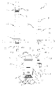
[0016] Fig. 1 is a front plan view of an illustrative embodiment electronic
faucet system
including a valve body assembly having an electrical cable extending therefrom
to a controller
assembly, and a spout assembly having an electrical cable extending therefrom
to the controller
assembly;
[0017] Fig. 2 is a block diagram illustrating the electronic faucet system
of Fig. 1;
[0018] Fig. 3 is a top, front side perspective view of the spout assembly
of Fig. 1;
[0019] Fig. 4 is a perspective view similar to Fig. 3, with a partial cut-
away thereof,
showing the sensor assembly and the spray head coupling exploded from the
spout;
[0020] Fig. 5 is a bottom, rear perspective view of the spout assembly of
Fig. 1, with a
partial cut-away thereof and with the spray head removed for clarity, showing
the sensor
assembly and the spray head coupling exploded from the spout;
[0021] Fig. 6 is a perspective view of an electrical cable of the spout
assembly of Fig. 1
including a first end and a second end;
[0022] Fig. 7 is a partial perspective view of the spout assembly of Fig.
1, with a partial
cut-away thereof, showing various components of the spout assembly exploded
therefrom
including a first electrical cable holder and a second electrical cable
holder;
[0023] Fig. 8 is a perspective view the first electrical holder of Fig. 7;
[0024] Fig. 9 is a perspective view of the first electrical holder of Fig.
7, with the
electrical cable of Fig. 6 assembled thereto;
CA 02532510 2006-01-06
=
-5-
[0025] Fig. 10 is a sectional view of a lower portion of the
spout assembly of Fig. 1, with
the fluid conduit removed for clarity, illustrating the placement of the first
electrical holder and
the electrical cable of Fig. 9;
[0026] Fig. 11 is a perspective view of the valve body assembly
of Fig. 1;
[0027] Fig. 12 is a perspective view of a base member of the
valve body assembly of Fig.
11, the base member including a retainer member;
[0028] Fig. 13 is a perspective view, with partial cutaways
thereof, of the electrical cable
of the valve body assembly of Fig. 11, the electrical cable including a sleeve
attached thereto;
[0029] Fig. 14 is a view, taken along line 14-14 of Fig. 12,
showing the interaction
between the retainer member of the valve body assembly of Fig. 12 and the
sleeve of the
electrical cable of Fig. 13 when the two are assembled together;
[0030] Fig. 15 is a cross-sectional view taken along line 15-15
of Fig. 14, showing the
placement of the retainer member of the base member proximate to another
component of valve
body assembly, illustratively a nipple, to aid in the retainment of the
electrical cable by retainer
member;
[0031] Fig. 16 is a perspective view of an illustrative
embodiment sensor assembly of Fig.
4;
[0032] Fig. 17 is an exploded perspective view of the sensor
assembly of Fig. 16;
[0033] Fig. 18 is a perspective view of the spray head coupling
of the spout assembly of
Fig. 14, with a cut-away of the fluid conduit for clarity;
[0034] Fig. 19 is a top plan view of the spout assembly of Fig.
1;
[0035] Fig. 20 is a cross-sectional view taken along line 20-20
of Fig. 19;
[0036] Fig. 21 is a cross-sectional view taken along line 21-21
of Fig. 19, showing the
spray head coupled to the delivery spout;
[0037] Fig. 22 is a cross-sectional view similar to Fig. 21,
showing the spray head
uncoupled from the delivery spout; and
[0038] Fig. 23 is a perspective view of a further illustrative
embodiment spray head
coupling, showing the spray head uncoupled from the delivery spout.
CA 02532510 2012-06-26
'-6-
DETAILED DESCRIPTION OF THE DRAWINGS
(00391 Referring initially to Figs. 1 and 2, an illustrative electronic
faucet system 100 is
shown fluidly coupled to a hot water source 101A and a cold water source 101B.
Faucet system
100 includes a spout assembly 102 and a valve body assembly 104 mounted to a
sink deck 105.
As explained in more detail herein and in one or more of the Related
Applications, including U.S.
Patent No. 8,104,113, titled -Position-Sensing Detector Arrangement for
Controlling a Faucet",
spout assembly 102
illustratively includes several electronic sensors. More particularly, spout
assembly 102
illustratively includes a sensor assembly 103 having an infrared sensor
generally in an upper
portion 106 of spout assembly 102 to detect the presence of an object, such as
a user's hands.
Sensor assembly 103 further illustratively includes a Hall effect sensor
positioned in upper
portion 106 to detect when a pull-out or pull-down spray head 108 is spaced
apart from upper
portion 106 (as shown in Fig. 22), for example when a user is directing water
flow to desired
objects within a sink basin 109. Sensor assembly 103 additionally
illustratively includes a
capacitance touch sensor wherein fluid flow from spout assembly 102 may be
activated by the
user touching spout assembly 102. Additional sensors or electronic devices may
be positioned
within or attached to spout assembly 102.
10040j Due to the presence of electronics (such as the described sensors)
generally within
upper portion 106, a spout control electrical cable 120 is contained within a
delivery spout 110 of
spout assembly 102 and provides electrical communication between sensor
assembly 103 and a
controller 116. Illustratively, controller 116 includes a battery compartment
117 operably
coupled to a control unit 119. Additional details of the controller 116 are
provided in one or
more of the related applications, including US Patent No. 7,625,667, titled
"Battery Box Assembly".
[00411 Valve body assembly 104 also illustratively includes several sensors
as explained
in more detail in one or more of the related applications including US Patent
No. 7,537,023, titled
-Valve Body Assembly with Electronic Switching".
Valve body assembly 104 illustratively includes a
CA 02532510 2006-01-06
-7-
conventional manual valve member (such as a mixing ball or disc) to provide
for the manual
control of the flow and temperature of water in response to manual
manipulation of a handle 118
supported for movement relative to a holder 114. A Hall effect sensor (not
shown) is
illustratively positioned in holder 114 to detect a position of the manual
valve member, and
hence, the handle 118. Valve body assembly 104 further illustratively includes
a capacitance
touch sensor (not shown) wherein fluid flow from spout assembly 102 may be
activated by the
user touching valve body assembly 104. Additional sensors or electronic
devices may be
positioned within or attached to valve body assembly 104. Due to the presence
of electronics
(such as the described sensors) generally within holder 114, a valve control
electrical cable 130
is contained within holder 114 and provides electrical communication with
controller 116.
[0042] With further reference to Fig. 2, the faucet system 100 is in fluid
communication
with hot water source 101A and cold water source 101B. The valve body assembly
104
illustratively mixes hot water from the hot water source 101 and cold water
from the cold water
source 101 to supply a mixed water to an actuator driven valve 132 through a
mixed water
conduit 131. Illustratively, the actuator driven valve 132 comprises a
conventional magnetically
latching solenoid valve of the type available from R.P.E. of Italy. The
actuator driven valve 132
is controlled by the controller 116 through an electrical cable 128 and, as
such, controls the flow
of mixed water supplied to the spout assembly 102. As shown in Figs. 1 and 2,
the valves 104
and 132 are arranged in series and are fluidly coupled by mixed water conduit
131. The spout
assembly 102 is configured to dispense mixed water through spray head 108 and
into
conventional sink basin 109.
[0043] As shown in Figs. 1 and 2, when the actuator driven valve 132 is
open, the faucet
system 100 may be operated in a conventional manner, i.e., in a manual control
mode through
operation of the handle 118 and the manual valve member of valve body assembly
104.
Conversely, when the manually controlled valve body assembly 104 is set to
select a water
temperature and flow rate, the actuator driven valve 132 can be touch
controlled, or activated by
proximity sensors when an object (such as a user's hands) are within a
detection zone to toggle
water flow on and off.
100441 In an illustrative embodiment, the actuator driven valve 132 is
controlled by
electronic circuitry within control unit 119 that implements logical control
of the faucet assembly
100. This logical control includes at least two functional modes: a manual
mode, wherein the
CA 02532510 2012-06-26
-8-
actuator driven valve 132 remains open, and a hands-free mode, wherein the
actuator driven
valve 132 is toggled in response to signals from a proximity sensor. Thus, in
the manual mode,
the faucet assembly 100 is controlled by the position of the handle 118 in a
manner similar to a
conventional faucet, while in the hands-free mode, the flow is toggled on and
off in response to
the proximity sensor (while the flow temperature and rate are still controlled
by the handle 118
position).
100451 Illustratively, the faucet assembly 100 is set to operate in a hands-
free mode by
user interaction, for example by input from a push-button, by input from a
strain gauge or a
piezoelectric sensor incorporated into a portion of the faucet assembly 100,
such as the spout
assembly 102, or by input from a capacitive touch button or other capacitive
touch detector. It
will be appreciated that a touch control, whether implemented with a strain
gauge or a capacitive
touch-sensor can respond to contact between a user and the handle 118 that is
insufficient to
change a position of the handle 118.
(0046] The capacitive touch control may be incorporated into the spout
assembly 102 of
the faucet assembly 100, as taught by US Patent No. 6,962,168, titled
"Capacitive Touch On/Off Control
for an Automatic Residential Faucet". In certain
illustrative
embodiments, the same mode-selector can be used to return the faucet assembly
100 from hands-
free mode to manual mode. In certain of these illustrative embodiments, as
detailed herein, a
touch-sensor is also incorporated into the handle 118. In such illustrative
embodiments, the two
touch controls can either operate independently (i.e. mode can be changed by
touching either one
of the touch controls), or together, so that the mode is changed only when
both touch controls are
simultaneously touched.
(0047) In certain alternative embodiments, once placed in hands-free mode
the faucet
assembly 100 can be returned to manual mode simply by returning the manual
faucet control
handle 118 to a closed position. In addition, in certain illustrative
embodiments the faucet
assembly 100 returns to manual mode after some period of time, such as 20
minutes, without
user intervention. This time-out feature may be useful for applications in
which power is
supplied by batteries, because it preserves battery life. In one illustrative
embodiment, once the
hands-free mode is activated, the actuator driven valve 132 is closed,
stopping the water flow.
This state is the hands-free standby state, in which water flow will be
activated by a proximity
CA 02532510 2006-01-06
. .
,
-9-
detector. The manual valve handle 118 preferably remains in the open position.
In other words,
the manual valve body assembly 104 remains open, so that flow is halted only
by the actuator
driven valve 132.
100481 In the hands-free standby state, objects positioned
within the sensor's trigger zone
cause the faucet assembly 100 to enter the hands-free active state, wherein
the actuator driven
valve 132 is opened, thus permitting the water to flow. The faucet assembly
100 remains in
hands-free active mode, and the actuator driven valve 132 remains open, as
long as objects are
detected within the sensor's trigger zone. When objects are no longer detected
in the sensor's
trigger zone, the faucet assembly 100 returns to hands-free standby mode, and
the actuator driven
valve 132 closes.
100491 It will be appreciated that water flow is important
while a user is attempting to
adjust the flow rate or temperature. More particularly, the user observes
these properties as they
are adjusted, in effect completing a feedback loop. Thus, adjustment of the
flow properties is
another case in which water flow is preferably activated without requiring the
user to place his or
her hands or an object in the trigger zone. Therefore, in the illustrative
embodiment, when the
faucet assembly 100 is in standby hands-free mode, the faucet assembly 100
switches to active
hands-free mode, and the actuator driven valve 132 is opened, whenever the
manual control
handle 118 is touched.
[0050] In certain alternative embodiments, when the handle 118
is touched while in
hands-free mode, the faucet assembly 100 switches to manual mode, which will,
of course, also
result in activating the water flow (unless the handle is closed), as well as
the deactivation of the
proximity sensor. If the user wishes to then return to hands-free mode, he or
she may reactivate
it in the usual way, such as by a touch control.
10051] In the illustrative embodiment, the faucet assembly 100
does not immediately
enter the hands-free mode when the manual valve body assembly 104 is opened
and released.
Instead, the faucet assembly 100 enters a "quasi-hands-free" state, in which
the faucet assembly
100 continues to be manually controlled, and the actuator driven valve 132
remains open. This
quasi-hands-free state persists as long as the proximity sensor does not
detect the presence of an
object within the sensor's trigger zone. This allows the faucet assembly 100
to function as a
normal manual valve when initially operated, but to switch modes to hands-free
automatically
when sensing the presence of an object within the trigger zone. The advantage
of this quasi-
CA 02532510 2006-01-06
-10-
hands-free mode is that the faucet assembly 100 can be operated as a
conventional manual faucet
without the necessity of manually selecting the manual mode. This is valuable,
for example, in
single-use activations such as getting a glass of water or when guests use the
faucet assembly
100. In these embodiments, when the user initially opens the faucet assembly
100 and adjusts
the water temperature or flow rate and then releases the handle 118, the water
does not
immediately shut off, thereby frustrating the user's attempt to operate the
faucet assembly 100 as
a manual faucet. After the user has adjusted the flow, and places an object
within the faucet
assembly's detection zone, the faucet assembly 100 will then enter hands-free
mode.
[0052] Because the behavior of the faucet assembly 100 in response to its
various input
devices is a function of the mode it is presently in, illustratively, the
faucet assembly 100
includes some type of low-power indicator to identify it's current mode.
Appropriate indicators
include LEDs (light emitting diodes), LCDs (liquid crystal displays), or a
magnetically latching
mechanical indicator. In certain embodiments, the mode indicator may simply be
a single bit
indicator (such as a single LED) that is activated when the faucet assembly
100 is in hands-free
mode. Alternatively, the mode indicator may include a separate bit display for
each possible
mode. In still other embodiments, the mode indicator may indicate mode in some
other way,
such as a multi-color LED, in which one color indicates hands-free mode, and
one or more other
colors indicate other modes. Additional details regarding the mode indicator
are provide herein.
Further, transition between modes may illustratively be indicated by an audio
output.
[0053] When a user is finished using the faucet assembly 100, the faucet
assembly 100 is
illustratively powered down and returned to a baseline state. Powering down
provides power
savings, which makes it more feasible to operate the faucet assembly 100 from
battery power.
Returning the faucet assembly 100 to a baseline state is helpful because it
gives predictable
behavior when the user first begins using the faucet assembly 100 in a
particular period of
operation. Preferably, the baseline state is the manual mode, since the next
user of the faucet
assembly 100 might not be familiar with the hands-free operation.
Illustratively, a user is able to
power down the faucet assembly 100 and return it to the manual, baseline mode
simply by
returning the manual handle 118 to the closed position, because this is a
reflexive and intuitive
action for users.
[0054] As a consequence, the illustrative embodiment faucet assembly 100 is
configured
to sense whether the handle 118 is in the closed position. It will be
appreciated that this can be
CA 02532510 2006-01-06
-11-
accomplished directly, via a sensor in the valve body assembly 104 that
detects when the manual
valve member is closed, such as by including a small magnet in the handle 118,
and an
appropriately positioned Hall effect sensor. Alternatively, the handle
position can be observed
indirectly, for example by measuring water pressure above and below the manual
valve, or with
a commercial flow sensor. However, it will be appreciated that this inference
(that the handle
118 is in a closed position) is only valid if the electrically operable valve
is open. It will be
appreciated that, because the actuator driven valve 132 is controlled
electronically, this is easily
tracked by the controller 116. Thus, in the illustrative embodiment, the
faucet assembly 100 is
returned to manual mode when both the actuator driven valve 132 is open and
water is not
flowing through the faucet assembly 100.
100551 Illustratively, the faucet assembly 100 also includes a "watchdog"
timer, which
automatically closes the actuator driven valve 132 after a certain period of
time, in order to
prevent overflowing or flooding. In certain of these illustrative embodiments,
normal operation is
resumed once an object is no longer detected in the sensor's trigger zone. In
certain other
illustrative embodiments, normal operation is resumed once the manual valve
body assembly
104 is closed. In still other illustrative embodiments, normal operation is
resumed in either event.
In those illustrative embodiments including a hands-free mode indicator, the
indicator is flashed,
or otherwise controlled to indicate the time-out condition.
100561 In addition to the various power-saving measures described above,
the illustrative
embodiment also includes an output mechanism that alerts users when batter
power is low. It
will be appreciated that any suitable output mechanism may be used, but
illustratively an LED
and an audio output are used.
100571 With reference to Figs. 1 and 3-6, electrical cable 120 includes a
first end 122
having a connector 123 which is electrically coupled to a circuit board 127
(Fig. 4) in upper
portion 106 of spout assembly 102, and a second end 124 having a connector 125
which is
electrically coupled to the controller 116.
100581 Controller 116 and hence at least a portion of electrical cable 120
is positioned
underneath the sink deck 105 to which spout assembly 102 and valve body
assembly 104 are
attached. Electrical cable 120 may be subject to unexpected jerks or other
external forces under
the sink deck 105 that may place an axial force generally in direction 126 on
electrical cable 120
(Fig. 4). Such axial force 126 may cause the movement of electrical cable 120
within delivery
CA 02532510 2012-06-26
-12-
spout 110, such as within upper portion 106, and may break a wire in
electrical cable 120 or
connector 123, and/or unplug connector 123 from circuit board 127. Movement of
electrical
cable 120 may influence the operation of the capacitance touch sensor in spout
assembly 102
because such movement may be interpreted by the capacitance touch sensor as a
"false touch
event" (i.e., the sensor erroneously thinks a user has touched delivery spout
110). Also, a
movement of electrical cable 120 may prevent a "real touch event" (a user
actually touching the
sensor tube) from activating fluid flow from spout assembly 102.
100591 With reference to Figs. 7-9, in order to prevent or minimize the
movement of
electrical cable 120 within delivery spout 110 and/or to prevent or minimize
the strain exerted on
electrical cable 120 within delivery spout 110 due to axial forces in
direction 126, a spout first
strain relief member or electrical cable holder 200 is provided proximate to a
lower portion 112
of spout assembly 102 and a spout second strain relief member or electrical
cable holder 300 is
provided proximate to upper portion 106 of spout assembly 102. By preventing
or minimizing
the strain exerted on electrical cable 120 within delivery spout 110 due to
axial forces in
direction 126, first electrical holder 200 provides strain relief to the
electrical cable 120 of spout
assembly 102.
100601 Referring further to Fig. 7, a partially exploded view of an
illustrative
embodiment of spout assembly 102 is shown. Additional details about the
operation of spout
assembly 102 are provided herein and in one or more of the Related
Applications including U.S.
Patent No. 8,104,113, titled "Position-Sensing Detector Arrangement for
Controlling a Faucet".
100611 With reference to Figs 6-10, first spout electrical holder 200
supports a middle
portion 121 of electrical cable 120, which is positioned generally proximate
to a lower portion
112 of spout assembly 102. First spout electrical holder 200 includes a lower
portion 202 and an
upper portion 204. Lower portion 202 couples first electrical holder 200 to
spout assembly 102
and upper portion 204 holds or retains electrical cable 120.
100621 As shown in Figs. 8 and 9, upper portion 204 includes a base member
206 and a
plurality of extending protrusions or legs 208, illustratively shown as three
legs 208A, 208B,
208C, and 208D. In alternative embodiments, the number and relative
positioning of legs 208
may vary. Legs 208A-D are shown as being spaced apart and generally linearly
arranged. In
CA 02532510 2006-01-06
'
-13-
alternative embodiments, the legs may be spaced apart and arranged in a non-
linear fashion.
Each of legs 208A-D include a foot or tab 210A-D, respectively. Tabs 210A-D
limit the
movement of electrical cable 120 along a longitudinal extent of legs 208A-D.
Tabs 210A-D
project outward to a side of the respective leg 208A-D that electrical cable
120 is contacting as
shown in Fig. 9. In Fig. 9, tabs 210A-D are arranged in an alternating fashion
due to the
placement of electrical cable 120.
[0063] In alternative embodiments other types of holders may be used for
first electrical
holder 200, such as a clip similar to clip 152 which interacts with a sleeve,
such as sleeve 160, or
other suitable means for preventing or minimizing the movement of electrical
cable 120, such as
clamps.
[0064] Lower portion 202 includes a finger 212 which includes an opening
214.
Referring to Fig. 10, opening 214 is sized to receive a fastener 216 which is
threadably received
in a spout hub 218 of spout assembly 102. Finger 212 is offset relative to
legs 208A-D by a
ledge 220 which rests upon an upper portion 222 of spout hub 218.
[0065] Referring further to Fig. 9, middle portion 121 of the electrical
cable 120 when
assembled to first electrical holder 200 includes multiple bends. In the
illustrative embodiment,
electrical cable 120 is passed through legs 208A-D such that electrical cable
120 has a generally
serpentine path. This bending of electrical cable 120 about legs 208A-D, the
rigidity of the first
electrical holder 200, and the stiffness of cable 120 prevents or minimizes
the movement of
electrical cable 120 relative to first electrical holder 200 when an axial
force is applied in
direction 126. As such, by placing first electrical holder 200 proximate to
the lower portion 112
of spout assembly 102, the movement of electrical cable 120 within delivery
spout 110 due to the
application of an external force in direction 126 is reduced, and
illustratively minimized.
[0066] By placing first electrical holder 200 on a proper position of
electrical cable 120,
unintended movement of electrical cable 120 within spout housing 110 may be
reduced or
prevented. In one embodiment, the portion of electrical cable 120 held by
first electrical holder
200 is selected such that an additional portion of electrical cable is
contained within spout
housing 110 and follows an inner surface thereof. It is characterized as an
additional portion
because it is a longer section of electrical cable than is needed to span the
distance from upper
portion 106 to lower portion 112. Due to the stiffness of the electrical cable
120 when an
appropriate additional portion of electrical cable is selected, the electrical
cable 120 within spout
CA 02532510 2006-01-06
-14-
housing 110 will be at least partially compressed thereby minimizing the
movement of the
electrical cable within spout housing 110. In another embodiment, the portion
of electrical cable
120 held by first electrical holder 200 is selected such that electrical cable
120 is held firmly
between first electrical holder 200 and second electrical holder 300 thereby
minimizing the
movement of the electrical cable 120.
[0067] With reference to Figs. 6 and 7, spout second electrical holder 300
supports
electrical cable 120 generally proximate to first end 122 which includes
connector 123 for
connection to circuit board 127. Spout second electrical holder 300 is
illustratively defined by
support bracket 472 as detailed herein, and illustratively includes a cradle
302. Cradle 302
includes a surface 304, illustratively shown as being generally cylindrical,
which generally mates
with an exterior surface 129 of electrical cable 120. When spout assembly 102
is assembled,
electrical cable 120 is held in place due to a contact between surface 129 of
electrical cable 120
and surface 304 of cradle 302, and due to a contact between surface 129 and an
inner surface 306
of delivery spout 110.
[0068] In alternative embodiments other types of holders may be used for
second
electrical holder 300, such as a clip similar to clip 152 which interacts with
a sleeve, such as
sleeve 160, or other suitable means for preventing or minimizing the movement
of electrical
cable 120, such as clamps.
[0069] Referring now to Figs. 1, 11, and 13, electrical cable 130 of valve
body assembly
104 includes a first end 133 having a connector 134 which is electrically
coupled to a circuit
board 135 in valve body assembly 104 (Fig. 13) and a second end 136 having a
connector 137
which is electrically coupled to controller 116. As stated before, controller
116 and hence at
least a portion of electrical cable 130 are positioned underneath the sink
deck 105 to which spout
assembly 102 and valve body assembly 104 are attached. Electrical cable 130
may be subject to
unexpected jerks or other external forces under the sink deck 105 that may
place an axial force
generally in direction 138 on electrical cable 130 (Fig. 11). Such axial force
138 may cause the
movement of electrical cable 130 within holder 114, may break a wire in
electrical cable 130 or
its associated connectors 134 and 137, and/or unplug connectors 134 and 137.
The movement of
electrical cable 130 within holder 114 may influence the operation of the
capacitance touch
sensor in valve body assembly 104 because such movement may cause a false
touch event or
frustrate a real touch event.
CA 02532510 2006-01-06
-15-
[0070] In order to prevent or minimize the movement of electrical cable 130
within
holder 114 and/or to prevent or minimize the strain exerted on electrical
cable 130 within holder
114 due to axial forces in direction 138, valve strain relief member or valve
electrical cable
holder 400 (Figs. 12, 14 and 15) is provided. By preventing or minimizing the
strain exerted on
electrical cable 130 within holder 114 due to axial forces in direction 138,
valve electrical cable
holder 400 provides strain relief to the electrical cable 130 of valve body
assembly 104.
[0071] Referring to Fig. 11, valve body assembly 104 is shown. A lower
portion 140 of
valve body assembly 104 includes a base member 142, a gasket 144, and
associated plumbing or
water conduits 146. Referring to Fig. 12, base member 142 includes a central
opening 148 for
receiving conduits 146 and electrical cable 130. Base member 142 further
includes a retainer
150, which defines the valve electrical cable holder 400 by holding or
otherwise restraining the
movement of electrical cable 130. Retainer 150 is illustratively shown as an
arcuate clip 152
extending from an inner wall 154 of base member 142. In one illustrative
embodiment, clip 152
is made of a resilient material such that an end portion 156 may be further
spaced apart from
inner wall 154 to receive electrical cable 130 and thereafter at least
partially return towards inner
wall 154 to retain electrical cable 130.
[0072] In the illustrated embodiment shown in Figs. 14 and 15, clip 152
clips over
electrical cable 130 directly below a first end portion 162 of a sleeve 160
which is coupled to
electrical cable 130. In one embodiment, sleeve 160 is a molded component
coupled to electrical
cable 130. In alternative embodiments, the sleeve 160 may be integrally formed
with the
electrical cable 130. First end portion 162 of sleeve 160 has a radial extent
large enough to
prevent the passage of sleeve 160 into an opening 158 of clip 152. As such,
sleeve 160 prevents
the axial movement of electrical cable 130 is direction 138 due to the
interaction between first
end portion 162 of sleeve 160 and clip 152.
[0073] Referring further to Fig. 14, sleeve 160 illustratively further
includes a second end
portion 164, and a reduced diameter intermediate portion 166 located between
first end portion
162 and second end portion 164. In one embodiment, clip 152 receives reduced
diameter
intermediate portion 166 of sleeve 160 such that any axial movement of
electrical cable 130 is
limited by the contact of clip 152 with one of first end portion 162 or second
end portion 164.
As such, sleeve 160 may prevent the movement of electrical cable 130 in both
axial directions
relative to clip 152.
CA 02532510 2012-06-26
-16-
100741 Referring further to Figs. 14 and 15, sleeve 160 is shown assembled
with clip 152.
In one embodiment, base member 142 is keyed such that base 142 assembles to
other
components of valve body assembly 104 in a particular orientation. In one
illustrative
embodiment, clip 152 is oriented when base member 142 is assembled such that
clip 152 is
adjacent to another component of valve body assembly 104, illustratively a
mixed water outlet
nipple 168. By placing clip 152 in close proximity with another component,
such as nipple 168,
the other component provides a second mechanism for insuring that electrical
cable 130 remains
retained by clip 152.
100751 In alternative embodiments other types of holders may be used for
first electrical
holder 400, such as a plurality of projecting legs which orient cable 130 such
that cable 130 has a
generally serpentine path, or other suitable means for preventing or
minimizing the movement of
electrical cable 120, such as clamps.
[0076) With reference now to Figs. 3-5, spout assembly 102 includes an
outlet 402
fonned in upper portion 106 which receives sensor assembly 103 and a retainer
404 for
removably coupling spray head 108 to delivery spout 110. Sensor assembly 103
includes a
bracket 406 which is mechanically and electrically connected to the delivery
spout 110 at an
interface 408 (Fig. 20). The bracket 406 may be coupled to the inner surface
of the delivery
spout 110 through conventional means, including brazing, welding, gluing or
other similar
methods. The bracket 406 has a threaded opening 410 at a first end and is in
electrical
communication with a circuit board 127 at a second end 412. The bracket 406
provides
electrical communication between the delivery spout 110 and a capacitive
sensor supported on
the circuit board 127. More particularly, a connector 411 (Fig. 20) on the
circuit board 127
engages with the second end 412 of the bracket 406. It should be noted that
the combined
delivery spout 110 and bracket 406 may be chrome plated or have another
similar finish applied
thereto.
[0077) With reference to Figs. 4, 5, 16, and 17, sensor assembly 103
further includes a
plastic holder 414 which supports the circuit board 127, an infra-red (IR)
sensor 416, a light pipe
418, and a sliding member 420. The IR sensor 416 may be of the type detailed
in one or more of
the related applications including US Patent No. 8,104,113, titled "Position-
Sensing Detector Arrangement
for Controlling a Faucet".
CA 02532510 2012-06-26
-17-
A reflector 422 cooperates with the light pipe 418 and is
configured to assist in directing light from light emitting diodes (LEDs) 423
to a forward
projecting lens 424. More particularly, light pipe 418 butts up against LEDs
mounted on the
circuit board 127. Illustratively, when the system 100 is in a hands-free (IR)
mode, the LEDs
will flash in one color. Further illustratively, when the system 100 is in a
touch mode, the LEDs
will display a second color. The selected colors may be those available from
any commercially
available LED.
(0078) An insulator or gasket 426 isolates the PR sensor 416 from the spout
bracket 406
to facilitate proper operation by eliminating undesired contact on the IR
sensor 416. A cable
assembly 428 provides electrical communication between the IR sensor 416 and
the circuit board
127.
[0079] A lens 430 is coupled to the holder 414 by a conventional fastener,
such as a
threaded bolt 432, passing through an opening 434 formed in the lens 430 and
an opening 436
formed within the holder 414. The fastener 432 is threadably received within
the opening 410 of
the bracket 406. In other words, the fastener 432 traps the lens 430 and
engages with the
threaded opening 410 of the bracket 406 to restrain the front end of the
sensor assembly 103. A
retention pin 438 is slidably received within an opening 440 formed in the
delivery spout 110
and is received within a slot 442 of the holder 414 to secure the rear of the
sensor assembly 103.
A trim piece 444 may be received over the holder 414 for aesthetics. Retainer
404 is threadably
received within a lower portion 448 of the holder 414 and retains the trim
piece 444. The lens
430 is configured to project through an opening 450 of the trim piece 444 and
protect the 1R
sensor 416. More particularly, the retainer 404 includes an externally
threaded ring 452 which
passes through an opening 453 of the trim piece 444 and is threadably received
within an
internally threaded opening 454 of the holder 414. An annular retaining lip
456 abuts the trim
piece 444 and, as such, couples it to the holder 414.
100801 The sliding member 420 is illustratively formed of a thermoplastic
material and
includes a holder 460 and a guide member 462. The holder 460 is configured to
retain a sensing
element, such as an embedded magnet 464 (Fig. 16). The guide member 462 is
configured to
slide in the direction of arrows 465A and 465B within a slot 466 formed within
the holder 414.
Illustratively, a biasing member, such as a spring 468 is configured to bias
the sliding member
420 in a direction away (arrow 465B) from the outlet of the delivery spout
110. The spring 468
CA 02532510 2006-01-06
is illustratively supported on a post 470 formed integral with the sliding
member 420, and
extends between the guide member 462 and a support bracket 472.
100811 The support bracket 472 is substantially U-shaped and includes
upwardly
extending first and second legs 474 and 476 supported by the holder 414. A
connector 478
connects the first and second legs 474 and 476 and defines a second electrical
holder 300,
including cradle 302 for supporting electrical cable 120, as further detailed
below. A tab 480
extends outwardly from the second leg 476 and includes an opening 482 for
receiving the post
470 supporting spring 468.
100821 A fluid conduit, illustratively a flexible hose 484 of conventional
design is
coupled to the spray head 108. The spray head 108 is of conventional design
and includes a
waterway 486 received within an outer housing or ring 488. As is known in the
art, rotation of
the outer housing 488 relative to the waterway 486 changes the flow of water
between an aerated
stream and a spray through operation of a diverter (not shown). A collar,
illustratively a hose nut
490 engages with a lower surface 492 of the guide member 460 of the sliding
member 420 as the
spray head 108 is moved upwardly into its coupled position with the delivery
spout 110. As may
be appreciated, the hose nut 490 may be a separate element supported for
movement with the
spray head 108, or may be formed integral with the waterway 486 or the hose
484.
100831 When the spray head 108 is coupled to the delivery spout 110, the
sliding member
420 is pushed upwards by the hose nut 490. When the spray head 108 is
uncoupled from the
delivery spout 110, the sliding member 420 moves down due to gravity and
biasing force exerted
by the spring 468. The magnet 464 cooperates with a Hall effect sensor 494
mounted on the
circuit board 127 to sense the relative position of the sliding member 420
and, as such, the spray
head 108. In an illustrative embodiment, when the sensor 494 detects that the
spray head 108 is
uncoupled from the outlet of the delivery spout 110, the controller 116
instructs the valve 132 to
automatically turn on the water flow. More particularly, in a further
illustrative embodiment the
Hall effect sensor 494 transmits a signal representative of the relative
position of the spray head
108 to the controller 116, which, in response thereto, places the system 100
in a particular mode
of operation (i.e. hands-free, touch, or manual).
100841 The retainer 404 illustratively includes a plurality of inwardly
extending arms 498
circumferentially spaced within the opening 500 defined by the threaded ring
452. The arms 498
are illustratively integrally formed with the threaded ring 452 and are biased
inwardly. Tabs 502
CA 02532510 2006-01-06
-19-
are formed at the lower end of the arms 498 and are configured to engage an
annular groove 504
formed within the waterway of the spray head 108. Engagement between the tabs
502 and the
groove 504 couple the spray head 108 to the delivery spout 110. Retention is
facilitated by the
flexible nature of the arms 498. In the illustrative embodiment, an elastomer
pad 506 is
positioned radially outwardly from each arm 498 and is configured to assist in
biasing the arms
504 inwardly. The elastomeric pads 506 provide extra compression set and creep
resistance to
the arms 498. If the arms 498 or trim piece 444 are damaged, the retainer 404
can be easily
removed and either component replaced.
[0085] With reference to Fig. 18, the retainer 404 illustratively includes
four
circumferentially spaced arms 498, although the number and spacing of the arms
498 may vary.
The sides of the arms 498 include chamfered surfaces 508 to provide easy
docking of the spray
head 108. A straight land area 510 of each arm 498 is configured to engage
with an adjacent tab
or rib 512 formed on the waterway 486 of the spray head 108. The engagement
between the
areas 510 and the ribs 512 prevents relative rotation between the waterway 486
of the spray head
108 and the retainer 404. As such, a rotation of the outer housing 488 of the
spray head 108 is
resisted by the waterway 486, such that relative rotation occurs between outer
housing 488 and
waterway 486. This allows the conventional diverter to change fluid flow
between an aerated
stream to a spray in response to rotation of the outer housing.
[0086] While the illustrative embodiment retainer 404 utilizes
circumferentially spaced,
inwardly biased arms 498 to couple the spray head 108 to the delivery spout
110, it should be
appreciated that other couplers may be substituted therefor. For example, a
conventional
bayonet coupler or retainer 404', as shown in Fig. 23, may be used to couple
the spray head 108
to the delivery spout 110. More particularly, the retainer 404' illustratively
includes a slot 514
including a circumferential portion 516 and an axial portion 518. The slot 514
is configured to
receive a pin 520 supported by the waterway hose 484 at the spray head 108'.
Pin 520 of spray
head 108' is inserted into circumferential portion 516 of slot 514 and then
moved upwardly and
rotated until it is axially locked by a retaining surface 522. Operation of
the diverter (not shown)
to toggle water flow between a stream and a spray is controlled by a push
button 524.
[0087] With reference now to Figs. 7 and 10, spout hub 218 is received
within the lower
portion 112 of spout 110. Illustratively the spout hub 218 is formed of brass
and secured to
spout 110 in a conventional manner, for example through brazing. A valve body
assembly 528 is
CA 02532510 2012-06-26
-20-
illustratively removably received within the spout hub 218 for securing the
spout assembly 102
to the sink deck 105. The valve body assembly 528 illustratively includes a
valve body 530
formed of a metal, such as brass, and including a threaded portion 532
configured to receive a
securing nut 534.
100881 A base 536, illustratively formed of a plastic, is received around
the valve body
530 and is supported above the sink deck 105. A sealing gasket 538,
illustratively formed of a
resilient material, is positioned intermediate the base 536 and the sink deck
105. A mounting
washer 540 and an isolator 542 are secured below the sink deck 105 by the
securing nut 534.
More particularly, the sink deck 105 is clamped between the base 536 and the
isolator 542 by the
securing nut 534, thereby securing the spout assembly 102 to the deck 105. A
friction spacer
544 is positioned on valve body 530 and is frictionally received within the
spout hub 218. An
electrical clip 546 is received around the valve body 530 and provides
electrical communication
between valve body 530 and spout hub 218. If electrical communication (or
isolation) between
valve body 530 and the capacitance touch sensor is inconsistent, "false touch
events" may occur
due to unintended, and typically sporadic, electrical isolation (or
communication). By
maintaining electrical communication between valve body 530 and spout hub 218,
and hence
spout 110 and capacitance touch sensor through brackets 306, such instances of
"false touch
events" may be reduced or eliminated.
100891 Although the invention has been described in detail with reference
to certain
preferred embodiments, variations and modifications exist within the scope of
the invention
as described herein.