Note : Les descriptions sont présentées dans la langue officielle dans laquelle elles ont été soumises.
CA 02532906 2011-03-31
Divided or Interconnected After-Run Vehicle Interior Heating System
Background of the Invention
The present invention generally relates to automotive and vehicular
heating systems, and more particularly, to an improved separated or connected
system
for continuing the heating of an automotive or vehicular interior after the
engine has been
turned off.
In conventional vehicular heating systems having a water-cooled
engine, a hot water circulation conduit or circuit is provided which uses the
heated
engine coolant to provide heat to the passenger compartment of the vehicle.
When the
engine is operating, hot coolant from the engine is circulated through a
heater core. A
heater fan pushes air through the core, where it is heated by the hot engine
coolant, and
then into the passenger compartment. Accordingly, in these conventional
heating
systems, it was necessary to leave the engine idling, even when the vehicle
was
stationary or unoccupied, in order to keep a vehicle's passenger compartment
warm.
Only with the engine idling could hot coolant be pumped through the heater
core. Such
excessive idling causes unnecessary fuel consumption and air pollution.
In order to prevent such excessive idling, after-run heaters have been
developed for continuing the heating of vehicle interiors even after the
engine is turned
off.
After-run heaters utilize much of the coolant heat by transferring it into
the passenger compartment. An example of such a heater is shown in Perhats, U.
S.
Patent No. 4,308, 994. A magnetically-coupled pump with low battery drain,
along with
CA 02532906 2011-03-31
WH-12848 CA
SN 2,532,906
auxiliary control components, is utilized to circulate the still-hot engine
coolant through
the vehicle's heater core and to run the vehicle's heater fan while the engine
is off.
Those skilled in the art will recognize that systems of the type shown in
the 4,308,994 patent require the interconnection between components located
within the
passenger compartment and components located within the engine compartment.
More
specifically, components such as the seasonal switch, indicator and fan motor
controls
are located in the passenger compartment inside or under the dash, whereas the
engine
coolant pump and temperature sensor are located in the engine compartment. The
interconnection of these components requires the installing of wiring through
the firewall
between the two compartments. The wiring may pass through the firewall. This
type of
system is referred to herein as an interconnected system. Those skilled in the
art will
recognize that, depending on the specific configuration of the vehicle's
firewall, engine
compartment and dash, installation of an interconnected system can prove to be
time-
consuming, difficult, and therefore very costly.
These problems were addressed in the after-run heater of Perhats, U. S.
Patent No. 6,116, 552. A pump and first control circuit therefore are located
in the engine
compartment of the vehicle. The first control circuit allows the pump to
continue
circulating heated engine coolant through the heater core of the vehicle after
the engine
has been turned off. A second control circuit, located in the passenger
compartment of
the vehicle, continues to operate the heater fan which blows air through the
heater core
and into the passenger compartment after the engine has been turned off.
The first and second control circuits have no mechanical, electrical or
electromagnetic interconnection therebetween but nevertheless are interrelated
and
codependent. This type of system is referred to herein as a divided system.
2
CA 02532906 2006-01-18
WO 2005/014316 PCT/US2004/018904
Those skilled in the art will recognize that installation of after-run heating
systems involves a broad range of vehicles sizes, types and styles.
Accordingly, the system and
its installation can prove to be costly due to the required specificity in
manufacture, distribution
and inventory for each vehicle. Furthermore, in some vehicles the arrangement
of the heating
system, firewall and related components renders installation of the
interconnected after-run
heating system relatively straightforward. That is, there is no need for the
divided system of the
6,116,552 patent. In other vehicles it can range from difficult to impossible
to install the
interconnected system of the 4,308,994 patent. In such vehicles the divided
after-run heating
system of the 6,116,552 patent is required.
Summary of the Invention
In view of the foregoing, it is desirable to develop an after-run heating
system
which is configurable at installation as an interconnected system, with
through the firewall
connections, or as a divided system, with no mechanical, electrical or electro-
magnetic connec-
tion extending through the firewall.
It is further desirable to develop an after-run heating system whose passenger
and engine components are easily interconnected between the firewall placed
therebetween.
It is further desirable to develop an after-run heating system which accommo-
dates the varying installation needs of vehicles of varying size, type and
style.
The present invention provides a system for controlling after-run heating of a
vehicle's interior comprising, a pump and a control means thereof, usually
located in the engine
compartment, and a related but separate vehicle fan control means located in
the driver's
compartment. This after-run heating system is configurable at installation as
a single intercon-
3
CA 02532906 2006-01-18
WO 2005/014316 PCT/US2004/018904
nected system or as a divided system with no mechanical, electrical or electro-
magnetic
connection between the separated components. The components in both the engine
and passen-
ger's compartments function synergistically and co-dependently, either as an
interconnected or
divided system.
The present invention provides a single, convertible system, that can be
configured by the installer at the time of installation, as a single,
interconnected system or, when
necessary, as a divided system with engine compartment and passenger
compartment compo-
nents separated mechanically, electrically, and electro-magnetically but
operating together as
functionally codependent elements of the system.
These and other desired benefits of the preferred forms, including combina-
tions of features thereof, of the invention will become apparent from the
following description.
It will be understood, however, that a device could still appropriate the
claimed invention
without accomplishing each and every one of these desired benefits, including
those gleaned
from the following description. The appended claims, not these desired
benefits, define the
subject matter of the invention.
Brief Description of the Drawings
Fig. 1 is a circuit diagram of a fan control system, located in the passenger
compartment, installed as a separated system.
Fig. 2 is a circuit diagram of a pump/thermostat control system, located in
the
engine compartment, installed as a separated system.
Fig. 3 is a circuit diagram of a fan control system and a pump/thermostat
control system, connected to one another so as to form a directly connected
system.
4
CA 02532906 2006-01-18
WO 2005/014316 PCT/US2004/018904
Fig. 4 is a circuit diagram of an alternate embodiment, showing connection
between the fan control component and an existing vehicle heater fan when a
heater relay is
available.
Detailed Description of the Invention
Looking at Fig. 1, vehicular heating systems, even those not having an after-
run heating system, generally comprise a heater fan motor 5 connected to a
power source
through line 7. The power source is typically in the form of a battery or
alternator. A ground
line 6, a fuse/circuit breaker 8, and a fan speed control switch 12 complete
the fan motor circuit.
When the vehicle ignition is turned on, the heater fan motor 5 is connected to
the power source,
via an existing power supply conductor 7. On the other hand, when the vehicle
ignition is off,
the heater fan motor 5 is disconnected from the power source so that the
heater fan motor 5 will
not operate even if the fan speed control switch 12 is on.
In accordance with the goals of this invention, the main functioning compo-
nents that provide pumping and engine coolant temperature sensing (module 1 of
Figs. 1 and 2,
and the fan control module 3 of Figs. 1 and 3) are convertible at
installation, that is, they can be
set up either as a separated, unconnected system or as a connected system with
through-the-
firewall connections. These components are identically-configured, whether the
system is
separated or connected.
Figs. 1 and 3 illustrate an after-run heating system which uses the existing
vehicle heater to continue vehicle interior heating. More specifically, a
method for directly
connecting an after-run heating circuit to an existing heater fan includes
severing conductors 9
and 11 and inserting the fan control module 3 into the fan circuit as follows.
Conductor 11 is
CA 02532906 2006-01-18
WO 2005/014316 PCT/US2004/018904
connected to the movable transfer contact 16 of a fan control relay 14.
Conductor 9 is connected
to a fixed contact 15. With fan control relay 14 dormant (ignition on), the
original source of
heater fan power is restored, with the transfer contact 16 of fan control
relay 14 closed upon
fixed contact 15. This causes current to flow from the power source, to
fuse/circuit breaker 8, to
fan control relay 14, to the fan speed control switch 12, and to the heater
fan motor 5.
The after-run heating system may be adapted such that fan control module 3
controls the heater fan motor 5. Fan control module 3 is connected to vehicle
battery 17 via
conductor 19, vehicle battery 17 being further connected to vehicle ground by
way of conductor
18. During normal operation of the vehicle during winter, the existing vehicle
heater is supplied
with hot engine coolant by way of the engine coolant pump. Heat from the
engine coolant is
transferred to the passenger compartment by the running of the heater fan
motor 5. Thermostat
26 of fan control module 3 is located in the heater plenum chamber outlet.
When heated by the
warm air emanating from the heater during normal winter vehicle operation,
thermostat 26
closes contacts 27, 28.
With contacts 27, 28 closed and after-run heating system on/off switch 22
closed, battery power from vehicle battery 17 is supplied to fuse/circuit
breaker 20, to on/off
switch 22, to a connector receptacle 30, to a connector plug 31, to plenum air
sensing thermostat
26, to a connector plug 34, to a connector receptacle 35, and to the contacts
of an ignition-on
sensing relay 38. Ignition-on sensing relay 38 is connected to vehicle ground
via conductor 39
and is powered via conductor 40, which may be connected to any power source
that cycles on
and off with vehicle ignition.
When the vehicle ignition is turned on, power is supplied to relay 38 which
causes movable contact 37 to disengage from fixed contact 36, thereby opening
the power
6
CA 02532906 2006-01-18
WO 2005/014316 PCT/US2004/018904
supply circuit to fan control relay 14. When fan control relay 14 is dormant,
movable contact 16
is positioned on fixed contact 15, thereby returning fan control to its
original vehicle power
source. When vehicle ignition is turned off, battery power is removed from
conductor 40 and
ignition-on sensing relay 3 8 becomes dormant, thereby causing contact 37 to
reengage contact
36, transferring battery power to fan control relay 14, and causing contact 15
to engage with
contact 25 via contact 16.
In an alternate embodiment, an after-run heating system may be adapted such
that power to heater fan motor 5 may be controlled by fan control module 3.
With on/off switch
22 closed, power is supplied by battery 17 to fuse/circuit breaker 20, to
on/off switch 22, to fan
control relay 14, to fan speed control switch 12, and to heater fan motor 5,
thereby placing heater
fan motor 5 under the operating control of fan control module 3 and allowing
the fan motor 5 to
run even with the ignition and engine turned off.
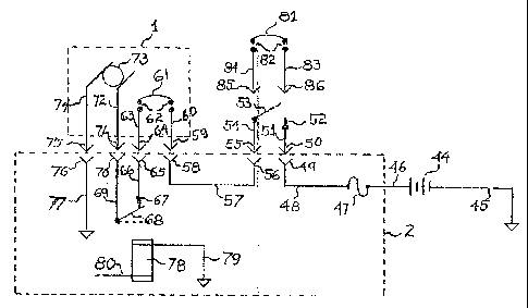
Fig. 2 illustrates a circuit diagram of a pump/thermostat and control system
therefor, located in the engine compartment and installed as a separated
system. Pump control
module 2 is generally connected to pump/thermostat module 1. Vehicle battery
44 is connected
to ground via conductor 45. Vehicle battery 44 provides power to pump control
module 2, to
fuse 47, to connector receptacles at connections at 49 and 56, to connector
receptacle at 58 via
conductor 57, and to a thermostat plug 59 of pump/thermostat module 1.
When the vehicle is driven, the engine pump forces hot engine coolant
through the dormant after-run heating system pump 73. The after-run heating
system pump may
be generally located in series with the supply hose of the vehicle passenger
compartment heater.
Thermostat 61 is generally an integral part of the pump/thermostat module 1.
Thermostat 61
senses the heated coolant and is adapted to open or close contacts 62. For
example, thermostat
7
CA 02532906 2006-01-18
WO 2005/014316 PCT/US2004/018904
may sense the heated coolant and close contacts 62 upon sensing a temperature
of 1600 F and
opens contacts 62 when coolant temperature is reduced to approximately 95 F.
Accordingly,
battery power is transferred from the plug 59 to thermostat 61, to plug 64, to
connector recepta-
cle 65, and to the contacts 67, 68 of ignition-on sensing relay 78. When the
vehicle engine is
running, battery power is supplied to ignition-on sensing relay 78, which
thereupon opens fixed
contact 67 from engagement with moveable contact 68. Hot water continues to be
supplied to
the vehicle heater by way of the engine pump.
When the ignition is turned off, battery power is removed from conductor 80,
such that ignition-on sensing relay 78 becomes dormant. Ignition-on sensing
relay 78 then
closes moveable contact 68 which engages fixed contact 67, thereby
transferring battery power
from the thermostat 61, to ignition-on sensing relay contacts 67, 68, to a
connector receptacle 70,
to a plug 71, to after-run heating system pump 73, to ground via conductor 74,
plug 75, connec-
tor receptacle 76 and conductor 77. In this arrangement, the after-run heating
system pump 73
commences pumping hot engine coolant to the vehicle passenger compartment
heater, thereby
effectively substituting the pumping action of the engine pump. This assembly
may be used in
conjunction with fan control module 3, which continues heater fan operation as
discussed above.
Those skilled in the art will appreciate that such interacting assembly allows
for the passenger
compartment of the vehicle to be heated, even with the engine and ignition
turned off.
As the after-run heating system continues to operate, thermostat 61 may be
adapted to open contacts 62 when the engine coolant drops to a designated
temperature, thereby
terminating operation of the after-run heating system pump 73. For example,
the thermostat 61
may be adapted to terminate the after-run heating system pump 73 when engine
coolant drops to
approximately 95 F. In the separated system embodiment of Fig. 1 and Fig. 2,
the after-run
8
CA 02532906 2006-01-18
WO 2005/014316 PCT/US2004/018904
heating system pump 73 ceases to pump cool engine coolant to the passenger
compartment
heater, which thereupon begins to cool plenum air sensing thermostat 26
located in the heater air
plenum. At a designated temperature, plenum air sensing thermostat 26 is
adapted to terminate
heater fan operation by opening contacts 27, 28 such that fan control relay 14
becomes dormant
and allows existing vehicle systems to control heater fan motor 5. With the
ignition turned off,
the power supply line 7 of the heater fan motor 5 is un-powered such that
heater fan motor 5
ceases operation.
In view of the foregoing, there is no electrical, mechanical or
electromagnetic
connection between pump/thermostat module 1 and heater fan module 3.
Therefore, the systems
operate independently, but synergistically, to initiate and terminate the
heating operation of the
existing vehicle heater with the engine turned-off. Those skilled in the art
will recognize and
appreciate that this elimination of idling allows for the decrease of fuel
consumption, air
pollution and costs in commercial operations.
It will be realized that the heater fan module 3 may be adapted to be turned
off, i.e. for seasonal operation, by operating on/off switch 22 of fan control
module 3, which is
located in the passenger compartment. Also, pump/ thermostat module 1 and
control means 2
thereof may be adapted to be turned off through the operation of a seasonal
on/off switch 53.
The pump/thermostat module I may also be adapted to accommodate automatic
termination.
For example, an ambient temperature sensor 81 may be substituted for the
manual on/off switch
53. In this case the on/off switch 53 plugs 50, 55 are disengaged from
connector receptacles 49,
56 and replaced by the ambient sensor 81 with its plugs 85, 86. Accordingly,
ambient sensor 81
may open or close contacts 82, thereby terminating or commencing operation of
pump/thermostat module 1.
9
CA 02532906 2006-01-18
WO 2005/014316 PCT/US2004/018904
Fig. 3 illustrates the heater fan control module 3 of Fig. 1 being directly
connected to pump/thermostat module 1 of Fig. 1 as an integrated system. In
the directly
connected system the plenum air sensing thermostat 26 and pump control module
2 are
disconnected and removed from the system.
In this configuration and during normal vehicle operation (engine running),
fan control module 3 operates as follows: with system on/off switch 22 open
and ignition on, the
after-run heating system is disconnected from battery 17 and remains non-
operational when the
engine is turned off. Fan control relay 14 is also unpowered with transfer
contact 16 being
closed upon contact 15. Instead, the normal power source through line 7
provides power to
heating fan motor 5, which is connected to fuse/circuit breaker 8, to fan
control relay 14, and to
fan speed control switch 12, thus providing air movement means for the
passenger cabin.
With the ignition and engine turned off, battery 17 supplies power to fan
control module 3, which is connected to fuse/circuit breaker 20 and on/off
switch 22. Without
battery power, the pump/thermostat module 1 is unpowered and after-run heating
system pump
73 is dormant. If required while the vehicle is being driven, vehicle interior
heating may be
provided by the engine pump circulating engine coolant through the dormant
after-run heating
system pump 73 located in series with the hose supplying hot engine coolant to
the vehicle
heater. The flow of hot coolant also heats thermostat 61, thereby closing
contacts 62. When
engine (ignition) is turned off, the after-run heating system does not operate
because on/off
switch 22 remains open. The on/off switch 22 may be turned on or off at any
time during
vehicle operation. With on/off switch 22 turned on when engine is turned off,
the after-run
heating system is adapted to automatically pump hot engine coolant.
CA 02532906 2006-01-18
WO 2005/014316 PCT/US2004/018904
When the engine is turned off and on/off switch 22 and thermostat 61 are
closed, the system operates as follows: power is transferred from battery 17
to fuse/circuit
breaker 20, to on/off switch 22, to the connector receptacle 30, to plug 59,
to closed contacts 62
of thermostat 61, to plug 64, to connector receptacle 35, and to the contacts
36, 37 of the
ignition-on sensing relay 38. With the ignition turned off, ignition-on
sensing relay 38 does not
receive power from conductor 40. Therefore, upon transfer contact 37 being
closed upon
engagement with fixed contact 36, power is transferred at conductors 90 and
42.
In this arrangement, power is transferred from battery 17 from conductor 90
to after-run heating system pump 73, to continue circulation of hot water to
vehicle heater with
the engine turned off. At the same time, power is transferred from battery 17
to fan control relay
14, through closed on/off switch 22, and fuse/circuit breaker 20. Conductor
11, being connected
to transfer contact 16 of fan control relay 14, it powers heating fan motor 5
by way of fan speed
control switch 12, thereby causing heating fan motor 5 to run in conjunction
with after-run
heating system pump 73. This assembly allows for passenger compartment to be
heated even
with the engine turned off.
As the after-run heating system continues to operate, the thermostat 61 may
be adapted to open contacts 62 when the engine coolant reaches a designated
temperature,
thereby terminating operation of the after-run heating system pump 73. For
example, the time
thermostat 61 may be adapted to terminate the after-run heating system pump 73
when it drops
to approximately 95 F. In one embodiment, time thermostat 61 is adapted'to
interrupt battery
power to after-run system pump 73 and fan control relay 14, thereby placing
both in a state of
dormancy and transferring contact 16 to re-engage with contact 15. This
engagement returns the
heater fan motor 5 to be controlled and powered by the original control power
sources.
11
CA 02532906 2006-01-18
WO 2005/014316 PCT/US2004/018904
Heater fan module 3 may also be adapted to be turned off, i.e. for seasonal
operation, by operating on/off switch 22 of fan control module 3, which is
located in the
passenger compartment.
An alternate method for connection to heating fan motor 5 is shown in Fig. 4.
A conductor 91 is connected to transfer contacts 16 of fan control module 3
and fan control relay
14 by replacing conductor 11 in either Figs. 1 or 3. The other end of
conductor 91 is connected
to existing vehicle heater relay 92 at the relay's positive terminal 93. This
arrangement is
adapted such that power is transferred to relay 92 when after-run heating
system is turned on and
vehicle ignition switch 96 is turned off. This arrangement is further adapted
such that when
vehicle ignition switch 96 is turned on, power from the battery 17 is
transferred to existing
heating relay 92 and contacts 98, 99 are closed. Upon closure of contacts 98,
99, power is
supplied from existing fuse/circuit breaker 8, to vehicle heater relay 92,
contacts 98, 99, to fan
speed control 12, and to heating fan motor 5.
When either the vehicle ignition switch 96 or after-run heating system are
turned off, power to vehicle heater relay 92 is interrupted, thereby opening
contacts 98, 99 and
interrupting power to the heating fan motor 5. Thus, with the after-run
heating system on and
hot engine coolant present in the engine cooling system, cycling of vehicle
ignition switch 96
alternately on and off puts heating fan motor 5 under the control of either
the after-run heating
system or original vehicle control.
While this invention has been described with reference to certain illustrative
aspects, it will be understood that this description shall not be construed in
a limiting sense.
Rather, various changes and modifications can be made to the illustrative
embodiments without
departing from the true spirit and scope of the invention, as defined by the
following claims. For
12
CA 02532906 2006-01-18
WO 2005/014316 PCT/US2004/018904
example, the temperature settings of the referenced thermostats could be other
than those
indicated. Also, the various components shown as mechanical sensors, circuit
breakers, and
electromagnetic relays could have electronic equivalents substituted therefor.
A battery voltage
monitor or timing device could also be placed in circuit to terminate system
operation upon
encountering low battery voltage or after a designated time period. An
auxiliary battery or
multiple vehicle batteries connected in parallel or with battery isolators for
supplying power only
to the after-run heating system from only one of the group of batteries, while
being capable of
being charged by the vehicle engine alternator, are all also contemplated. The
locations of the
plugs and connectors could be reversed, i.e., the module shown having a
receptacle could have a
plug and the mating module would have a receptacle instead of the plug as
shown. Also, it will
be understood that the plugs and receptacles could be at the ends of wires
having a length
suitable for the particular needs of a specific installation.
Furthermore, it will be appreciated that any such changes and modifications
will be recognized by those skilled in the art as an equivalent to one or more
elements of the
following claims, and shall be covered by such claims to the fullest extent
permitted by law.
13