Note : Les descriptions sont présentées dans la langue officielle dans laquelle elles ont été soumises.
CA 02533324 2006-O1-19
WO 2005/012884 PCT/GB2004/003176
HOLOGRAPHIC SENSOR
Field of the Invention
This invention relates to a holographic sensor.
Background to the Invention
WO-A-95/26499 discloses a holographic sensor. The sensor comprises
a holographic support medium and, disposed throughout its volume, a hologram.
The support medium interacts with an analyte, resulting in a variation of a
physical property of the medium. This variation induces a change in an optical
characteristic of the holographic element, such as its polarisability,
reflectance,
refractance or absorbance. If any change occurs whilst the hologram is being
replayed (e.g. using incident broad band, non-ionising electromagnetic
radiation), then a colour change, for example, may be observed using an
optical
detector. The optical detector may be a spectrometer or simply the human eye.
WO-A-99/63403 describes an alternative method of producing a
holographic sensor. A sequential treatment technique is used, wherein the
polymer film is made first and sensitive silver halide particles are added
subsequently. These particles are introduced by diffusing soluble salts into
the
polymer matrix where they react to form an insoluble light-sensitive
precipitate.
The holographic image is then recorded.
The holographic sensors described above are made by recording a
hologram using a plane mirror, which is holographed in a trough of suitable
liquid. Furthermore, the support media of the sensors are planar. This
arrangement may not always be effective if the sensor is to be used in an
environment where there is considerable light scatter, e.g. subcutaneously. In
addition, the optical detector must be placed at a particular position with
respect
to the sensor, in order to detect reflected light.
Summary of the Invention
The present invention is based on a realisation that the above problems
can be addressed by forming the hologram as a non-planar mirror. This can be
achieved in various ways, e.g. by recording the hologram using a non-planar
mirror and using non-planar support media.
CA 02533324 2006-O1-19
WO 2005/012884 PCT/GB2004/003176
2
Accordingly, a first aspect of the invention is a sensor comprising a
medium and, disposed therein, a hologram, wherein an optical characteristic of
the hologram changes as a result of a variation of a physical property of the
medium, and wherein the hologram is formed as a non-planar mirror.
A second aspect of the invention is a method for the production of a
sensor of the invention, which comprises forming, in a medium, a hologram as
a non-planar mirror.
Another aspect of the invention is a method for the detection of an
analyte, which comprises remotely interrogating, with light, the holographic
element of a sensor of the invention; and detecting any change in an optical
characteristic of the sensor.
The invention allows for the design of holographic sensors which can
reflect incident light in an accurate and predetermined fashion. The invention
may obviate the requirement for the optical detector to be "brought" to the
sensor. Indeed, the invention provides sensors which can be interrogated from
a wider range of angles and distances. Sensors of the invention may be used as
subcutaneous implants or in security, for example as authentication tags.
Brief Description of the Drawings
Figs. 1 and 2 are schematic views showing how a sensor of the invention
can be produced using, respectively, a concave mirror and a corner cube prism.
Fig. 3 is a side view of a probe suitable for interrogating a sensor of the
invention.
Fig. 4 is a schematic diagram showing the sensor of Fig. 1 being
interrogated.
Fig. 5 is the same as Fig. 4, except that the sensor is shown in a
subcutaneous environment.
Fig. 6 is a plan view of an annular sensor of the invention, formed using
a concave mirror.
Fig. 7 is a schematic diagram showing the sensor of Fig. 6 being
interrogated.
CA 02533324 2006-O1-19
WO 2005/012884 PCT/GB2004/003176
3
Figs. 8 and 9 are plan views of different embodiments of the invention,
each sensor being suitable for the simultaneous detection of a plurality of
analytes.
Fig. 10 is a ray diagram of a hologram formed as a concave mirror.
Fig. 11 is a schematic diagram showing a method of forming a sensor of
the invention.
Fig. 12 is a graph showing the angular tolerance of a sensor of the
invention.
Description of Preferred Embodiments
There are numerous ways in which the hologram can be formed as a non-
planar mirror. It will be appreciated that the various techniques described in
herein can be used alone or in combination, to achieve this effect.
A preferred embodiment of the invention involves recording the hologram
using a non-planar mirror. The type of mirror selected will depend on the
desired
effect that the resulting hologram will have on incident light. Many different
types
of non-planar mirror are known, for example, concave and convex mirrors (e.g.
semi-cylindrical mirrors), reflective beads and the like. Alternatively, the
mirror
may be a prism, for example a corner cube prism, a right angled prism, a Porro
prism, an Amici prism, a Dove prism, a Penta prism, a rhomboid prism or a
Lernan-Springer prism.
In a preferred embodiment, the mirror is a concave mirror. This allows for
the production of a sensor which has a focusing effect on incident light. Such
a
sensor has a wide range of possible uses, for example as a small subcutaneous
implant which can be conveniently interrogated using a fibre optic bundle.
Furthermore, to overcome the major obstacle of the problem of light scatter,
the
replay wavelength range can be adjusted to extend well into the near infra-
red.
Another advantage associated with the use of a concave mirror is that unwanted
specular white light is, in general, not focused by the hologram. Also, if
observed
from the opposite side, a concave hologram may have a convex mirror effect on
incident light, and vice versa.
Another preferred embodiment involves the use of a convex mirror, to
produce a hologram having an increased focal length and a collimating effect
on
CA 02533324 2006-O1-19
WO 2005/012884 PCT/GB2004/003176
4
incident light. An increased focal length is particularly desirable for
applications
where remote detection is required, for example the detection of an analyte in
a fuel tank.
The non-planar mirror may be one capable of effecting retroreflection,
such as a corner cube prism. Corner cube prisms typically reflect, up to a
certain
("tolerance") angle, any light entering the prism back towards the light
source,
regardless of the orientation of the prism. A hologram recorded using a corner
cube prism may therefore have a retroreflecting effect on incident light. Such
a
sensor is advantageous because the optical detector does not need to be placed
at a particular position with respect to the sensor. Another benefit
associated
with the use of a corner cube prism is that any response of the sensor can be
viewed from a wider range of angles (i.e. a greater angular tolerance) than
for
a conventional sensor.
A retroreflecting holographic sensor may be used to detect changes in
atmospheric conditions (e.g. humidity, temperature, levels of carbon dioxide
or
other chemically active gases) on a planet with an atmosphere. Detection may
be achieved by interrogating the sensor with a collimated light beam or other
remote light source. Such sensors may also be used to detect changes in
underwater environments. For example, changes in the levels of pH or ions
could be detected.
Alternatively, the non-planar mirror may consist of one or more reflective
beads. Reflective beads can be used to increase the intensity of the reflected
light and may also allow retroreflection.
It is preferred that the mirror is a dielectric material, since dielectric
materials have a high reflective efficiency . Alternatively, a parabolic
mirror may
be used, to minimise the effects of chromatic and spherical aberration.
The hologram may be recorded in a non-planar support medium. In this
case, the mirror need not necessarily be non-planar since the geometry of the
support medium defines that of the hologram.
The hologram may be recorded using a lens and an aperture/obstacle,
placed before the holographic recording material, during the recording
process.
When the hologram is recorded, radiation passes first through the lens and
CA 02533324 2006-O1-19
WO 2005/012884 PCT/GB2004/003176
aperture/obstacle, and then the recording material, before reaching the
mirror.
The resulting hologram may, as a consequence, have a specific diffraction
pattern. Such effects are desirable since they may result in a well-defined,
specific pattern of replay light. Lenses may also be used to change the object
5 size, collimate light or give a circular beam.
A holographic sensor of the type used in this invention generally
comprises a holographic support medium and, disposed throughout the volume
of the medium, a hologram. The support medium interacts with an analyte
resulting in a variation of a physical property of the medium. This variation
induces a change in an optical characteristic of the holographic element, such
as its polarisability, reflectance, refractance or absorbance. If any change
occurs whilst the hologram is being replayed by incident broad band,
non-ionising electromagnetic radiation, then a colour or intensity change, for
example, may be observed.
There are a number of basicways to change a physical property, and thus
vary an optical characteristic. The physical property that varies is
preferably the
size of the holographic element. This variation may be achieved by
incorporating specific groups into the support matrix, where these groups
undergo a conformational change upon interaction with the analyte, and cause
an expansion or contraction of the support medium. Such a group is preferably
the specific binding conjugate of an analyte species. Another way of changing
the physical property to change the active water content of the support
medium.
A holographic sensor may be used for detection of a variety of analytes,
simply by modifying the composition of the support medium. The medium
preferably comprises a polymer matrix, the composition of which must be
optimised to obtain a high quality film, i.e. a film having a uniform matrix
in which
holographic fringes can be formed. The matrix may be formed from the
copolymerisation of, say, (meth)acrylamide and/or (meth)acrylate-derived
monomers, and may be cross-linked. In particular, the monomer HEMA
(hydroxyethyl methacrylate) is readily polymerisable and cross-linkable.
PoIyHEMA is a versatile support material since it is swellable, hydrophilic
and
widely biocompatible.
CA 02533324 2006-O1-19
WO 2005/012884 PCT/GB2004/003176
6
Other examples of holographic support media are gelatin, K-carageenan,
agar, agarose, polyvinyl alcohol (PVA), sol-gels (as broadly classified),
hydro-
gels (as broadly classified), and acrylates. Further materials are
polysaccharides, proteins and proteinaceous materials, oligonucleotides, RNA,
DNA, cellulose, cellulose acetate, polyamides, polyimides and polyacrylamides.
Gelatin is a standard matrix material for supporting photosensitive species,
such
as silver halide grains. Gelatin can also be photo-cross-linked by chromium
III
ions, between carboxyl groups on gel strands.
The sensor may be prepared according to the methods disclosed in WO-
A-95/26499 and WO-A-99/63408. A suitable arrangement for this purpose is
shown in Figure 1 of the accompanying drawings. An alternative method is by
silverless double polymerisation, as described in PCT/GB 04/00976. The
contents of these specifications are incorporated herein by reference.
The invention will now be described by way of example only, with
reference to the accompanying drawings.
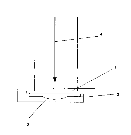
Fig. 1 shows how a hologram may be formed as a curved concave mirror.
A holographic plate 1 and a concave mirror 2 are present in an exposure bath
3. The holographic image is recorded using a spread laser beam 4. The term
"concave" is used herein in a broad sense, to describe any arrangement that
has
a focusing effect. The mirror may be, for example, spheric, aspheric (e.g.
parabolic) or it may comprise flat central and edge portions at an angle to
each
other. If such a mirror is made by the silverless double polymerisation method
described above, there is normally no liquid in the exposure bath in Fig.1.
Fig. 2 shows a process similar to that of Fig. 1, except that a corner cube
prism 5 is used, in place of the concave mirror.
As indicated above, a sensor of the invention is particularly suitable for
use in conjunction with a unit, e.g. of optical fibres, whereby light can be
transmitted to and from the hologram. A suitable bundle of fibres, ending in a
probe tip, is shown in Fig. 3. In a particular embodiment, the probe is about
5
mm in diameter, with an internal ring of six fibres, defining a circle 1 mm
across,
surrounding a central fibre.
CA 02533324 2006-O1-19
WO 2005/012884 PCT/GB2004/003176
7
In the particular embodiment shown in Fig. 3, the central fibre 6 leads to
a spectrometer read-out (not shown) and the ring fibres 7 are connected to a
white light illumination source (not shown). An alternative arrangement
comprises optical fibres at the spectrometer end in a line, one above the
other,
to coincide with, or substitute for, the normal spectrometer slit.
Corner cube devices are such that, if the incident light is diverging, then
the retroreflected light will continue to diverge, possibly resulting in a
poor signal.
Thus, it may be desirable to ensure that incident light is collimated or
converged.
In the case of the fibre optic arrangement of Fig. 3, this may be achieved by
placing a small convex lens (not shown) in front of the bundle.
The utility of the invention will now be described, with particular reference
to Figs. 4 and 5.
In Fig. 4, a sensor 8 formed using a concave mirror (see, for example Fig.
1 ) is shown interrogated in a non-scattering clear environment, using a fibre
optic bundle 9 as a probe. The hologram here returns the incident light 10 as
if
it were returning from the concave mirror used to make it. However, because it
was made with a particular laser wavelength, it becomes in effect a
monochromatic concave mirror. Furthermore, if made in a smart polymer, the
colour of the reflected light 11 will change with its environment. An
alternative
is to make it with more than one, well-separated laser wavelength, enabling it
to
sense different factors in its environment. For example, it could appear to be
simultaneously acting as a green, red or blue concave mirror, with the
separation
between the wavelengths much greater than the wavelength shifts likely to
occur
as it acts as a sensor, giving say a range of greens or reds but never large
enough to cause ambiguous results from wavelength overlaps. The ability of the
sensor to give a well-separated response to more than one analyte may be
achieved using a sensor having a layered structure, each layer comprising a
different material. Alternatively, the sensor may consist of different
materials
lying concentrically adjacent to each other throughout their depth.
The holographic concave mirror image focuses the coloured light onto the
central fibre. A valuable feature of working on axis (unlike conventional
techniques, where the diffracted light is arranged to reflect off at a
slightly
CA 02533324 2006-O1-19
WO 2005/012884 PCT/GB2004/003176
8
different angle to the specularly reflected light) is that, as the diffracted
wavelength changes, it remains focused on the central position.
Fig. 5 shows the same arrangement of Fig. 4, but in a diffusing
environment 12. This is typical of a subcutaneous implant.
In use, the intention is not necessarily to track changes in intensity of the
returning light. If as much as 99% of the light is lost due to scatter, then
being
able to track a small wavelength shift in the remaining 1 % from a very highly
diffracting implanted smart hologram may be satisfactory. In order to reduce
the
problem of scattered light, it may sometimes be helpful to make the hologram
with an off-axis concave mirror.
For use as an implant, the sensor may have to be covered with material
to reduce rejection problems. This should not affect the detection of analytes
found in the body, such as glucose or ions.
In a particular embodiment of the invention, a concave mirror sensor can
have its centre removed or covered so that it is in the form of a ring. This
is
illustrated in Figs. 6 and 7, the latter showing the sensor 13 being
interrogated
on a substrate 14. In this embodiment, provided that the light 15 provided by
probe 16 is centred on the middle of the ring (i.e. as if the full concave
mirror
were present) and spreads sufficiently to cover its area, then the hologram
will
continue to focus quasi monochromatic light 17 to the centre, just as it would
do
for a full concave mirror image. Other embodiments of the invention are shown
schematically in Fig. 8, where the concentric rings 18, 19, 20 illustrate an
arrangement for the detection of a variety of analytes.
Fig. 9 shows a holographic sensor comprising two sections, 21 and 22,
each comprising a hologram formed using a corner cube prism. Sections 21 and
22 can be used to detect a variety of different analytes. Both sections
reflect
incident light back to the light source (e.g. the fibre optic bundle
illustrated
herein), and thus the sensor may be used to detect two analytes
simultaneously.
Fig. 10 is a ray diagram of a hologram recorded using a convex mirror.
Use of a convex mirror of gradual curvature can allow for the production of a
sensor having an increased focal length F and a collimating effect on incident
light.
CA 02533324 2006-O1-19
WO 2005/012884 PCT/GB2004/003176
9
Fig. 11 shows how a sensor of the invention can be obtained by changing
the geometry of the support medium after the hologram has been recorded. In
Fig. 11, the planar sensor 23 is moulded into curved surface 24 to provide a
sensor 25 (the sensor shown in contact with the curved surface) having a
curved
support medium and, as a result, a focal point of reflection. This method can
be
used for sensors having a hologram recorded using a planar or non-planar
mirror. In the case of the latter, the focal point will be slightly off-
centre.
The following Example illustrates the invention.
Example
A support medium was formed by polymerising a mixture of 60 mole
acrylamide, 30 mole % methacrylamide, 4.9 mole % methylene bisacrylamide,
and 5.1 mole % 2-acrylamido-2-methyl-1-propanesulphonic acid. DMPA in
DMSO (433 ml) was used per 0.1961 g of dry constituents. 100 pl of mixture was
used per slide and polymerised for 30 minutes at 20.7°C.
AgN03 (0.25M, 400m1) was then soaked into the polymer for 2 minutes,
the excess wiped off and the slide dried for five minutes under a stream of
warm
air. The slide was then agitated for one minute using 4% (v/v) QBS dye in 1:1
methanol : water containing 4% KBr (v/v), and then rinsed in distilled water
to
remove excess bromide ions and any silver bromide remaining on the surtace.
The slide was placed polymer side down in a dish containing two adjacent
concave mirrors and a 60% ethanol (v/v) and water solution, and allowed to
settle for five minutes. The holographic image of the two mirrors was then
recorded using a laser.
The image was developed by using a 4:1 ratio of Saxby A: Saxby B
developer, rinsing in deionised water, placing in a stop solution (5% acetic
acid
{v/v}) and rinsing in deionised water a final time. The slide was then placed
in
sodium thiosulphate and agitated for 5 minutes, to remove excess silver and
QBS dye. The slide was then placed in methanol for around twenty minutes, to
remove any remaining dye.
The hologram was observed using a probe, which consisted of a fibre
optic bundle in conjunction with a 12.5 mm focal lens. The separation between
the bundle and the lens was the same as that between the lens and the sensor,
CA 02533324 2006-O1-19
WO 2005/012884 PCT/GB2004/003176
i.e. 25mm. Observation was made using a rig which allowed the angle of viewing
to be adjusted, at a constant probe distance. The peak diffraction wavelength
was noted at each angle until the peak disappeared into background noise.
The results are shown in Fig. 12. The use of a concave mirror in the
5 recording process meant that the response of the sensor was observed for a
greater range of angles than for a conventional sensor.