Note : Les descriptions sont présentées dans la langue officielle dans laquelle elles ont été soumises.
CA 02535673 2007-05-29
1
Device and Method for Fillina Foil Bans with Food
The invention relates to a device and a method for filling foil bags with
food. Here, food can be food
for both human consumption and for animals, such as pets or similar.
Devices for filling foil bags with drinks, i.e. liquid foods, are known. In
order to fill a desired quantity
the flow rate is determined during filling and filling is stopped when the
specified quantity is
reached.
The object of the present invention is to be able to fill foods other than
drinks into foil bags.
When filling solid foods, it is difficult to apply the principle for filling
liquids, since a continuous
transport of the solid foods up to a desired quantity is difficult or very
time-consuming.
The term food is intended to cover all consumable substances, i.e. including
those which are not
nutritious but which nonetheless may occur in comestibles.
The solid foods are preferably present as granulates, grains, in globular
shape, as pellets, sticks or
similar.
The device according to the invention has a dosing device with which a
predetermined quantity of
solid food can be measured. The quantity measured out in such a way can then
be transferred
quickly into the bag with a filling device for filling the foil bags with
solid foods. In the method, the
solid foods are first measured out and then filled into the foil bags. Because
of the fad that a
quantity is first measured out which is then filled, it is possible to fill
solid foods in dosed form and
to do so quickly.
In addition to filling with solid foods, filling with liquid foods may also be
provided. A mixture can
then form in the bag.
It is advantageous to have a dosing device with which various quantities can
be dosed, i.e. to be
able to fill different quantities. This means that, depending on the desired
composition of the bag
content, which may be made up of different components, a different quantity of
solid foods can be
filled.
Advantageously, the device has a dosing chamber the size of which can be
adjusted. In this way,
different quantities can be set. In this respect, the dosing chamber is
advantageously adjustable in
a telescope form. This allows the simplest possible construction of a size-
adjustable dosing
chamber.
CA 02535673 2006-02-08
2
The dosing chamber is advantageously formed in, at, on top of, below or near a
slide, so that the
dosing chamber can be moved with the slide, whereby the slide is moved by a
drive. The slide can be
separated from the drive, in response to a control command, so that if there
is no foil bag, the slide
and thus the dosing chamber are not moved in order to prevent any discharge of
solid food, since this
cannot be picked up by a foil bag.
A storage hopper for the solid food is advantageous. This can have a
distribution unit which
distributes the solid food evenly in the storage hopper. This ensures that
several foil bags are filled
evenly at the same time.
It is advantageous to provide a product line which ends at the filling
position of the foil bags. This
ensures the safe supply of the solid foods to the foil bags. Advantageously,
this product line is in the
form of a hopper so that the feeding of foods into the product line is as
simple as possible.
The product line is preferably movable, so that the end of the product line
can be moved into and out
of the foil bags. To fill the foil bags, it is advantageous if the product
line ends in the foil bag, whereas
it is advantageous for the transport of the foil bags before or after filling
if the product line ends
outside the foil bag.
Furthermore, it is advantageous if, at the upper end of or above the product
line, a fluid outlet is
provided with which a fluid can be passed into the product line. In this way,
it is possible to create a
gas or liquid buffer which prevents solid foods sticking to the product line.
The same fluid outlet or
another fluid outlet can also be provided, by which, for example, steam is
passed into the product line
in order to moisten it. This also prevents the solid foods from sticking.
For the transport of the foil bags, simple receptacles are advantageously
provided into which the foil
bags can be inserted. This guarantees the cheapest possible, mechanically
simple acceptance of the
foil bags for transport. The receptacles are designed in such a way that
suitable foil bags are slightly
open in the receptacle.
For wider opening for filling, pressure arms can be provided which press on
the foil bags at the side,
whereby these preferably have a shape which is adapted to an opened foil bag
in order to be able to
support the foil bag for the filling process. Pulling arms can also be
provided which pull up the foil bag
at its filling opening for the filling process.
With the method according to the invention, advantageously a dosing chamber is
moved back and
forth between a loading and an unloading position, whereby dosing is achieved.
Furthermore, with the method, advantageously the size of the dosing chamber is
changed so that
different quantities can be filled.
CA 02535673 2007-05-29
3
A method is advantageous in which a check is carried out to see whether there
is a foil bag to receive
the solid food at the filling position or not. If it is found that no foil bag
is present, the dosing chamber
is not taken to the unloading position, so that no food is wasted and the
machine is not soiled.
The product line with which the food is passed into the foil bag is preferably
movable. In this way, the
product line can be moved several times jerkily to the foil bag and away from
it in order to make sure
that the solid foods pass through the product line.
In one aspect, the present invention resides in a device for the filling of
foil bags with foods with a
transport device for transporting foil bags a dosing device comprising a
dosing chamber for
measuring out a predetermined quantity of solid foods a filling device for
filling the foil bags with the
measured quantity of solid foods and a closing device for closing the foil
bags wherein the dosing
chamber is formed in, at, on top of, below or near a slide which can be moved
by a drive, and the
slide can be separated from the drive in response to a control command.
In another aspect, the present invention resides in a device for the filling
of foil bags with foods with a
transport device for transporting foil bags; a dosing device for measuring out
a predetermined
quantity of solid foods; a filling device for filling the foil bags with the
measured quantity of solid foods;
and a closing device for closing the foil bags; wherein the dosing device has
a dosing chamber, the
size of which can be adjusted; and the dosing chamber is formed in, at, on top
of, below or near a
slide which can be moved by a drive.
In yet another aspect, the present invention resides in a method for the
filling of foil bags with foods
with the following steps transport of the foil bags; measuring out of a
predetermined quantity of soiid
foods; filling the foil bags with a measured quantity of solid foods; and
closing the foil bags; wherein a
closing chamber is loaded in a loading position and moved to an unloading
position, where its content
is unloaded into a foil bag; and a check is carried out to determine whether a
foil bag is available at a
filling position for foil bags and that, if this is not the case, the dosing
chamber is not taken into the
unloading position.
In a further aspect, the present invention resides in a method for the filling
of foil bags with foods with
the following steps transport of the foil bags; measuring out of a
predetermined quantity of solid
foods; filling the foil bags with a measured quantity of solid foods; and
closing the foil bags; wherein a
closing chamber is loaded in a loading position and moved to an unloading
position, where its content
is unloaded into a foil bag; and a foil bag is filled with an initial
quantity, then the size of the dosing
chamber is changed and a second foil bag is filled with a second, different
quantity.
Advantageous embodiments of the invention are illustrated in the attached
figures, in which:
CA 02535673 2007-05-29
3a
Figure 1 shows a schematic sectional drawing of a device;
Figure 2 shows a schematic sectional drawing of a device for filling;
Figure 3 shows a schematic sectional drawing of a dosing device;
Figure 4 shows a schematic illustration of a dosing chamber in various sizes;
Figure 5 shows a foil bag in various opening positions;
Figure 6 shows a product line and a foil bag;
Figure 7 shows a device to fill foil bags.
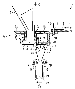
Figure 1 shows a device 1 for filling foil bags 24. Solid food can be held in
a storage hopper 2 in
order to be able to carry out a filling process for a long time without
topping up. The food can be
evenly distributed with a linear stirring unit 3 in the storage hopper 2. The
linear stirring unit moves
stirring rods or stirring brackets back and forth in the solid food. This
allows gentle handling with
even distribution in the storage hopper 2.
A dosing chamber 4 is shown underneath the storage hopper 2. This is bordered
at the side by two
cylindrical elements 5a and 7a. At the bottom, the dosing chamber 4 is closed
off by a plate 9. The
dosing chamber 4 is in the loading position here, since it is underneath the
storage hopper 2. The
cylindrical elements 5a and 7a are each connected with slide parts 5b and 7b.
These two slide parts
5b and 7b are connected with each other by a peg 15, whereby they can move
against each other in
the vertical plane in Figure 1. For this, the peg 15 engages with an opening
16 in the slide part 7b.
The peg 15 gives a good coupling of the slide parts 5b and 7b, whereby,
however, mobility in the
vertical plane is retained, which is important for the adjustment of the size
of the dosing chamber (see
below).
CA 02535673 2006-02-08
4
One of the two slide parts 5b, 7b (in this case, 5b) has an opening 10 with
which a movable pawl 11
can engage. The pawl 11 can be moved up and down along the direction 12. The
element 13
represents a drive which can be moved back and forth in direction 14. If the
pawl 11, as shown in
Figure 1, projects into the opening 10, then the slide part 5b is moved
together with the slide parts 5a
and 5c when the drive 13 is moved. Furthermore, the slide part 7b and thus
also the slide part 7a are
also moved by the peg 15. Using the drive 13, the entire dosing chamber 4 can
thus be moved if the
pawl 11 projects into the opening 10. If the pawl 11 is pulled out of the
opening 10, the entire dosing
chamber remains in its position. This is particularly advantageous for a
machine in which several
dosing chambers 4 are positioned next to each other which can all, however, be
moved with one and
the same drive 13. If a dosing chamber 4 is not to be moved, because for
example no foil bag is
present to be filled, then the pawl 11 can be pulled out of the opening 10 for
this dosing chamber 4 so
that when the drive 13 is moved for the other dosing chambers 4 which are to
be moved, the one
dosing chamber remains in its position. The pawl 11 is moved in the direction
12 preferably
automatically using for example a pneumatic, mechanical or hydraulics system
or an electricai motor.
The automatic operation is preferably connected with a sensor which determines
whether a foil bag is
in the filling position or not.
The plate 9 has an opening 26 above the hopper 17. If the dosing chamber 4 is
moved to the right
above this opening 26, the contents of the dosing chamber 4 can fall downwards
into the hopper 17.
Above the opening 26 in the plate 9 is the unloading position of dosing
chamber 4.
The lower opening of the storage hopper 2 and the opening 26 can also be
positioned further away
from each other in the horizontal direction in Figure 1. This can prevent
solid food being passed
through the opening 26 whilst the dosing chamber 4 is in a middle position
between the loading and
unloading position and new solid food sliding at the same time from the
storage hopper 2 into the
emptying dosing chamber 4.
Between the unloading position of the dosing chamber 4 and the filling hopper
17 a ring-shaped line
18 with openings is arranged. These openings can, for example, blow air into
the filling hopper 17, in
order to prevent the content of the dosing chamber 4, which falls into the
filling hopper 17, from
sticking to the filling hopper 17 or blocking it. The gas flowing out of the
ring line 18 forms a
compressed air buffer here.
A foil bag 24 can be arranged in a receptacle 23 at the lower end of the
filling hopper 17. Above the
foil bag 24, there are two rods 19, 20, which are supported so that they can
be swivelled. At the rods
19, 20, arms 21, 22 are positioned which can reach from above into the foil
bag 24 and open it wide
at its top side through a spreading movement of the arms 21, 22.
Transport of the foil bags 24 by the receptacles 23 is provided in the
direction 25.
CA 02535673 2006-02-08
Figure 2 shows a complete device for the filling of foil bags in schematic
form. Various receptacles 23
are provided with foil bags 24. Furthermore, a fllling pipe 40 is provided to
pass liquids 41 into the foil
bags 24. Furthermore, a filling hopper 17 for filling the foil bags 24 with
solid foods 42 is shown
schematically. The position of the filling pipe 40 and the filling hopper 17
can also be swapped over,
i.e. firstly solid and then liquid foods can be filled. In addition, heat-
sealing blocks 43 are shown, with
which the upper ends of an open foil bag can be heat-sealed with each other so
that these are leak-
tight. This forms a heat-sealing seam 44. The two heat-sealing blocks 43 can
each be swung away
upwards in order to take the next bag 24 into the position where the heat-
sealing blocks 43, which
have then been swung back down, can heat-seal a bag 24.
The receptacles 23 are then turned by 90 at the end of a conveyor so that the
foil bags 24 can be
removed with a gripper 45. The foil bags 24 which have been removed can be
deposited, for
example, on a conveyor belt 46 and thus transported away. The empty
receptacles 23 can be
transported back by the conveyor in order to be provided with a foil bag 24.
Figures 1 and 2 aim to explain the method according to the invention. Figure 2
shows how a foil bag
24 is inserted into receptacles 23, on the far right. The foil bag 24 is held
by the receptade 23 in such
a way that it is slightly open. Opening devices which will be discussed in the
following open the bag
24 in such a way that a filling pipe 40 can pass liquid into the foil bag 24.
The foil bag 24 filled with
liquid 41 in this way is transported in Figure 2 further to the left. As soon
as the foil bag 24 has arrived
under a filling hopper 17, this is opened again with the corresponding
devices, then the filling hopper
17 is lowered into the foil bag 24 and solid food 42 is filled into the foil
bag 24. For this, the dosing
chamber 4 is loaded in the loading position so that, through the volume of the
dosing chamber 4, a
defined quantity is measured out and then taken into the unloading position
above the filling hopper.
From there, the solid food is passed through the filling hopper 17 into the
bag 24. After this, the foil
bag 24 is heat-sealed with heat-sealing blocks 43 at its upper end, so that it
is sealed with a heat-
sealing seam 44. After this, the receptacles 23 are turned by 90 so that the
foil bags 24 are lying
horizontally and can be removed with a gripper 45. The gripper 45 places the
filled, sealed foil bags
24 onto a conveyor belt 46, which transports these away.
The device in Figure 2 works cyclically. Within one cycle, the bags are moved
on by one handling
position each time. Furthermore, it has a number of parallel filling lines
which are each equipped with
a filling hopper 17 and a filling pipe 41.
Figure 3 shows a simplified version of the filling device, to illustrate the
filling of the foil bags 24 with
solid foods 42. Instead of a dosing chamber 4, the size of which can be
adjusted, Figure 3 shows a
dosing chamber 4 with a fixed size. The explanations concerning Figure 3,
however, also apply
correspondingly for a dosing chamber 4 as shown in Figure 1.
CA 02535673 2006-02-08
6
Figure 3a shows the dosing chamber 4 which is formed in a single slide 27
underneath a storage
hopper 2. The lower end of the dosing chamber 4 is provided with a plate 9. In
the position in Figure
3a, solid food can pass from the storage hopper 2 into the dosing chamber 4.
Afterwards, the dosing
chamber 4 is moved to the right through the movement of the slide 27. In this,
part of the slide 27
closes the lower end of the storage hopper 2 so that nothing is discharged in
an uncontrolled way
from the storage hopper 2. Furthermore, to the right of the storage hopper 2,
a cover plate 28 is
provided which delimits the dosing chamber 4 upwards. The lower cover plate 9
has an opening 26
which is at the unloading position of the dosing chamber 4. If the dosing
chamber 4 is pushed over
this opening 26, the solid food can fall from the dosing chamber 4 into the
filling hopper 17. The
empty dosing chamber 4 can then be moved with the slide 27 back into the
position in Figure 3a,
where it can be loaded again.
Figure 4 shows schematically how the size of the dosing chamber 4 can be
changed. The cylinder
wall 7 and the lower plate 9 can be adjusted in height together.
Figure 4a shows a layout in which the cylinder 7 and the plate 9 are right at
the top so that the dosing
chamber 4 has a minimal volume.
Figure 4b shows a condition in which the dosing chamber 4' is medium-sized,
and Figure 4c shows
how the dosing chamber 4" has the maximum size.
In Figures 1 and 4, the dosing chamber 4 is formed by two cylinder walls 5 and
7. However, more
cylinder walls can also be provided which are positioned so that they can be
pushed into each other
like a telescope in order to obtain a larger adjustment range for the dosing
chamber.
Figures 1 and 4 show the wall thicknesses of the cylinder walls 5 and 7 as
being very thick. The walls
and 7 may also be made from thin metal sheets or similar.
The dosing chamber 4 can be adjusted automatically. Suitable means of
adjustment can be provided
for this, such as pneumatic, mechanical or hydraulic systems or electrical
motors.
If several dosing chambers 4 are provided for severai filling lines, the size
of the chambers can also
be adjustable with a common means of adjustment so that all the dosing
chambers 4 are changed in
the same way. For example, a common plate 9 can be provided, which is adjusted
in height so that
the cylinder walls 7 are also adjusted. For the adjustment of the plate 9,
four adjustment devices can
be provided at the corners of the plate 9 which are controlled, for example,
by a belt running around
the four corners.
Figure 5 shows foil bags 24 in the receptacles 23. The foil bags 24 have sides
31, 32, which are
lightly pressed together by the receptacle 23 so that the side foils 33 and 34
move apart from each
CA 02535673 2007-05-29
7
other and open up a filling opening 30. In order to open the filling opening
30 to a larger filling
opening 30', elements 35, 36 can be taken to the side of the foil bags 24 in
order to press the sides
31, 32 even closer together and thus obtain the larger filling opening 30'.
The elements 35, 36 have a
triangular recess with which they can support the side foils 33, 34 in the
opened state. At the tip of the
triangular recess in elements 35, 36 are slots 37 to take the side heat-sealed
seams at the sides 31,
32 of the foil bag 24. This provides a particularly good stabilisation of the
bags during filling.
The elements 35, 36 shown in Figure 5a and 5b can be provided both for filling
with liquid foods (see
filling pipe 40 in Figure 2) and for filling with solid foods (see filling
hopper 17 in Figure 2).
Figure 6 shows the lower end of the filling hopper 17, which has wedge-shaped
ends 38, 39. These
ends 38, 39 can easily be inserted into a slightly opened foil bag 30 so that,
when the filling hopper
17 is lowered, it opens the opening 30 of the foil bag 24 further so that the
lower end of the filling
hopper 17 can be inserted completely into the foil bag 24.
At the lower end of the filling hopper 17 (see Figure 6), side gas outlet
openings 16 can also be
provided which allow the gas flowing from the ring line 18 to be taken out of
the filling hopper 17
outside the foil bag 24. The openings should be small enough to ensure that
the solid food does not
pass through them.
The filling hopper 17 can also be provided with openings through which air or
liquid is passed into the
inside of the filling hopper 17. These openings can be provided over the full
length or only a part of
the filling hopper 17. It is advantageous to position these openings
particularly where the solid food
would hit the wall of the filling hopper, since the incoming air will thus
prevent the solid food from
sticking to the wall. The air forms an air buffer in this case. These openings
are particularly
advantageous at the lower end of the filling hopper 17, since here the danger
of the filling hopper 17
becoming blocked is particularly high, since the filling hopper 17 is
narrowest here. Water or a
cleaning liquid can also be passed into the filling hopper through the
openings for cleaning purposes.
Corresponding feed lines must be provided for the air or cleaning fluid on the
outside of the filling
hopper 17.
Figure 7 shows the lowering of the filling hopper 17 during filling in detail.
In Figure 7a, a receptacle
23 with a foil bag 24 has arrived underneath a filling hopper 17. A s 21, 22
from the swivelling rods
19, 20 are in an upper position so that the bag transport is not impeded. By
swivelling the rods 19, 20,
the a s 21, 22 can be moved into a lower position, whereby the upper side
foils of the foil bag 24
are pulled apart. This creates the space required for the filling hopper 17.
This situation is shown in
Figure 7b. After opening of the foil bag 24, the filling hopper 17 can be
lowered. Here, the lower
opening of the filling hopper 17 ends inside the foil bag 24. In the condition
shown in Figure 7b or 7c,
solid food can now be reliably filled into the foil bag 24. After the filling
hopper 17 has been lowered
into the condition shown in Figure 7c, it is advantageous to take the filling
hopper 17 once again into
CA 02535673 2006-02-08
8
the position of Figure 7b and then lower it again into the position in Figure
7c. The effect of this is that
any food that was stuck in the filling hopper 17 is loosened and passed into
the foil bag 24 when the
filling hopper 17 is lowered for the second time. After the foil bag 24 has
been filled, the filling hopper
17 is returned to the condition in Figure 7a, i.e. conveyed upwards until it
is above the foil bag 24 and
the rods 19, 20 are swivelled so that the arms 21 and 22 are in the upper
position once again (see
Figure 7a). The receptacle 23 can then be moved away to the side, which means
that the foil bag 24
is also moved away to the side.
The rods 19, 20 with the arms 21, 22 can also be used for opening for filling
with liquid products.
The device can have several filling lines positioned next to each other,
whereby, for example,
neighbouring receptacles 23 are connected with each other so that they can be
moved together. In
this way, for example, at least 10, at least 15 or even more filling lines can
be provided next to each
other, whereby every filling line comprises its own filling hopper 17 and its
own dosing device. The
filling lines can have a common storage hopper 2 and a common linear stirring
unit 3.