Note : Les descriptions sont présentées dans la langue officielle dans laquelle elles ont été soumises.
CA 02535794 2006-02-09
APPARATUS AND METHOD FOR MEASURING ZONAL INKING
FIELD OF THE INVENTION
The invention relates to an apparatus and method for
measuring zonal inking.
BACKGROUND OF THE INVENTION
During printing, a printing material is moved
successively through a plurality of printing units of a
press, as a rule a printing ink being applied to the
printing material in each printing unit. There is a
separate printing unit and therefore an inking unit for
each printing ink. The inking unit of each printing
unit has an ink metering device, the ink metering
device comprising a number of inking zone setting
elements, which are also designated ink slides or ink
blades, corresponding to the number of inking zones.
Depending on the position of the inking zone setting
elements, printing ink passes to an ink fountain roll
or ductor roll. The quantity of ink passing onto the
ductor roll as a function of the inking zone setting
elements for each inking zone is transferred by a
ductor roll or film roll onto an inking unit roll
arranged downstream of the latter and, via further
inking unit rolls, is moved in the direction of a forme
cylinder or plate cylinder of the respective printing
unit. What is known as a transfer cylinder or rubber-
covered cylinder, which transfers the printing ink from
the forme cylinder to the printing material, interacts
with the forme cylinder.
From the prior art, it is already known to measure the
zonal inking established on the printing material
during printing and, depending on this measurement, to
control the zonal inking of the inking units involved
in the printing. For this purpose, measurement regions,
CA 02535794 2006-02-09
- 2 -
what are known as print control elements, generally
printed outside a subject on the printing material, are
measured. However, it is also possible for measurement
regions within the subject to be measured.
In order to measure the zonal inking, use is made of
measuring devices which are based on a densitometric
and/or colorimetric and/or spectral measuring
principle. According to the prior art, in this case
each inking zone of a printed product to be measured is
either assigned an individual, stationary measuring
device or there is a common measuring device for a
plurality or all of the inking zones, which is moved in
a traversing manner along the printed product to be
measured. Stationary or static apparatuses for
measuring the zonal inking, which have a separate
measuring device for each inking zone, permit fast
measurement of a printed product but are expensive
because of the high expenditure on hardware.
Traversing apparatuses for measuring the zonal inking,
which have only one measuring device moved along the
inking zones, are less expensive but need a longer time
to measure a printed product.
SUMMARY OF THE INVENTION
From this starting point, the present invention is
based on the problem of providing a novel type of
apparatus for measuring the zonal inking and also a
corresponding method.
This problem is solved by an apparatus for measuring
the zonal inking. The apparatus according to the
invention comprises a large number of optical sensors,
which in each case pick up signals from at least one
zonal measurement region and pass them on to a
measuring device for evaluation, a plurality of optical
sensors passing on signals picked up from the same to a
common measuring device with the interposition of at
CA 02535794 2009-05-05
- 3 -
least one optical switch, the said measuring device
evaluating the signals provided by a variety of optical
sensors with a time offset or one after another.
The apparatus according to the invention for measuring
the zonal inking of a printed product combines the
advantages of the apparatuses known from the prior art.
Thus, because there are a large number of optical
sensors, the apparatus according to the invention
permits fast measurement of the printed product. The
fact that a plurality of optical sensors are connected
to one measuring device also reduces the expenditure on
hardware, so that the apparatus according to the
invention can also be implemented relatively cost-
effectively.
According to an advantageous development of the
invention, the optical switches are constructed as
multiplexers which, with the effect of time
multiplexing, pass on the signals supplied to the
respective multiplexer with a time offset to a device
connected downstream of the respective multiplexer.
In accordance with a first broad aspect, there is
provided an apparatus for measuring zonal inking on a
printed product having a plurality of inking zones,
comprising: a plurality of optical sensors picking up
signals from zonal measurement regions assigned to the
plurality of inking zones of the printed product; at
least one optical switch connected for receiving the
picked up signals from the plurality of optical
sensors; and at least one measurement device connected
to the at least one optical switch for receiving the
picked up signals and evaluating the picked up signals.
In accordance with a second broad aspect, there is
provided a method for measuring the zonal inking on a
printed product, comprising the steps of: picking up
signals from zonal measurement regions using a
CA 02535794 2009-05-05
- 3a -
plurality of optical sensors; passing the picked up
signals to a common measuring device with the
interposition of at least one optical switch; and
measuring, by at least one measuring device, the picked
up signals; and evaluating the picked up signals at the
measuring device to determine the zonal inking.
BRIEF DESCRIPTION OF THE DRAWINGS
Preferred developments of the invention emerge from the
following description. An exemplary embodiment of the
invention will be explained in more detail, without
being restricted thereto, by using the drawing, in
which:
Fig. 1 shows a schematic illustration of an apparatus
according to the invention for measuring the
zonal inking according to a first exemplary
embodiment of the invention;
Fig. 2 shows a schematic illustration of an apparatus
according to the invention for measuring the
CA 02535794 2006-02-09
- 4 -
zonal inking according to a second exemplary
embodiment of the invention;
Fig. 3 shows a schematic illustration of an apparatus
according to the invention for measuring the
zonal inking according to a third exemplary
embodiment of the invention; and
Fig. 4 shows a schematic illustration of an apparatus
according to the invention for measuring the
zonal inking according to a further exemplary
embodiment of the invention.
DETAILED DESCRIPTION
In the following text, the present invention will be
described in greater detail with reference to Figs 1 to
4.
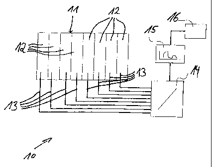
Fig. 1 shows an apparatus 10 for measuring the zonal
inking on a printed product 11 according to a first
exemplary embodiment of the invention. In the exemplary
embodiment of Fig. 1, the printed product 11 to be
measured has a total of eight inking zones 12. With the
aid of the apparatus 10 according to the invention, at
least one measured value relating to the zonal inking
in the inking zones 12 is to be determined for each of
the inking zones 12, for this purpose measurement
regions assigned to the inking zones 12 being measured,
specifically either measurement regions within a
subject or measurement regions outside a subject.
In the exemplary embodiment of Fig. 1, each inking zone
12 is assigned an optical sensor 13. With the aid of
the optical sensors 13, optical signals from at least
one measurement region to be measured can be picked up
for each inking zone 12. According to Fig. 1, all the
optical sensors 13 are connected to a common optical
switch 14. The signals picked up by the optical sensors
CA 02535794 2006-02-09
- 5 -
13 can be supplied to the optical switch 14 as input
signals, the optical switch 14 always supplying only
one of these input signals to a measuring device 15
connected downstream of the optical switch 14. In the
measuring device 15, the optical signals picked up by
the optical sensors 13 are evaluated densitometrically
and/or colorimetrically and/or spectrally and
corresponding measured values are supplied to a control
device 16, which can use the measured values to
regulate the zonal inking.
The optical switch 14 is constructed as an optical
multiplexer which, with the effect of time
multiplexing, passes on the signals supplied to the
multiplexer 14 by the optical sensors 13 with a time
offset to the device -15 connected downstream of the
multiplexer 14. In this way, optical signals can be
picked up simultaneously in all the inking zones and
supplied with a time offset to a single measuring
device. By this means, fast measurement of the zonal
inking over the entire printed product 11, specifically
over all the inking zones 12 of the same, can be
implemented with little expenditure on hardware.
A second exemplary embodiment of an apparatus 17
according to the invention for measuring the zonal
inking on the printed product 11 is shown by Fig. 2, in
the exemplary embodiment of Fig. 2 the printed product
11 again having a total of eight inking zones 12. In
the exemplary embodiment of Fig. 2, each inking zone 12
is again assigned a separate optical sensor 18. The
optical sensors 18 form two groups 19 and 20, the
optical sensors 18 of each group 19 and 20 being
connected to an optical switch 21 and 22, respectively,
in each case. The optical signals provided by the
optical sensors 18 are supplied to the optical switches
21 and 22 connected to the same as input signals,
output signals from the two optical switches 21 and 22
CA 02535794 2006-02-09
- 6 -
being supplied to an optical switch 23 connected
downstream of the same. Starting from this optical
switch 23, which is connected to the optical switches
21 and 22 with the effect of a cascade circuit, the
optical signals picked up by the optical sensors 18 are
passed on with a time offset to a measuring device 24,
which performs the densitometric and/or colorimetric
and/or spectral evaluation of the signals. The control
device 16 can again regulate the zonal inking on the
basis of the measured signals provided by the measuring
device 24.
In the exemplary embodiment of Fig. 2, the apparatus 17
according to the invention, just like the apparatus 10
according to the invention in the exemplary embodiment
of Fig. 1, has only a single measuring device 15 or 24,
which is used for the evaluation of all the optical
signals picked up by the optical sensors 13 and 18. In
the exemplary embodiment of Fig. 1, all the optical
sensors 13 are connected to a single optical switch 14.
In the exemplary embodiment of Fig. 2, on the other
hand, the optical sensors 18 are combined into groups,
the optical sensors 18 of each group 19 or 20 being
connected to an optical switch 21 or 22 in each case
and, starting from the optical switches 21 and 22
assigned to the groups 19 and 20, the optical signals
being supplied to the single measuring device 24 with
the interposition of a further optical switch 23.
A third exemplary embodiment of an apparatus 25
according to the invention for measuring the zonal
inking on the printed product 11 which, in the
exemplary embodiment shown, again has eight inking
zones 12, is shown by Fig. 3. In the exemplary
embodiment of Fig. 3, each of the inking zones 12 is
again assigned an optical sensor 26. The optical
sensors 26 are again structured in groups 27 and 28,
the measuring sensors 26 of each group 27 and 28 being
CA 02535794 2006-02-09
- 7 -
connected to an optical switch 29 or 30 in each case.
To this extent, the exemplary embodiment of Fig. 3
coincides with the exemplary embodiment of Fig. 2.
However, in the exemplary embodiment of Fig. 3, a
measuring device 31 and 32, respectively, is connected
downstream of each of the optical switches 29 or 30
assigned to a group 27 or 28, in which measuring device
the optical signals picked up by the optical sensors 26
of the respective groups 27 and 28 are evaluated
densitometrically and/or colorimetrically and/or
spectrally. Measured values from the measuring devices
31 and 32 can again be supplied to the control device
16.
A further exemplary embodiment of an apparatus 33
according to the invention for measuring the zonal
inking on a printed product 11 which, in the exemplary
embodiment shown, comprises a total of eight inking
zones 12, is shown by Fig. 4. In the exemplary
embodiment of Fig. 4, there are again a plurality of
optical sensors 34, in each case an optical sensor 34
being assigned to two inking zones 12. By means of a
traversing relative movement of the optical sensors 34
relative to the printed product 11 to be measured in
the direction of the arrows 35, appropriate optical
signals can be picked up by in each case one optical
sensor 34 on two adjacent inking zones 35. All the
optical sensors 34 are connected to a single optical
switch 36 which, with the effect of time multiplexing,
supplies the signals picked up by the optical sensors
34 to a single measuring device 37. The measuring
device 37 again evaluates the optical signals picked up
by the optical sensors 34 densitometrically and/or
colorimetrically and/or spectrally and provides
corresponding measured values to the control device 16.
Because of the spectral characteristics of the
measuring device 15, it may be necessary to distribute
CA 02535794 2006-02-09
- 8 -
the signal registered by the sensor 13 in a wavelength-
dependent or wavelength-independent manner to a
plurality of such measuring devices 15 and from there
to supply it to the control device 16.
For such a purpose, however, such a measuring device 15
can also comprise a plurality of subunits which cover
different spectral ranges and are given this signal by
means of an integrated optical switch, which
distributes the input signal in a wavelength-dependent
or wavelength-independent manner.
It is common to all the exemplary embodiments that
signals picked up via a plurality of optical sensors
are passed on to at least one measuring device for
evaluation, a plurality of optical sensors passing on
the signals picked up by the same to at least one
common measuring device with the interposition of at
least one optical switch. Further variants of the
invention beyond the practical exemplary embodiments
shown in Figs 1 to 4 are conceivable. For example,
optical sensors traversing over two, three or even four
inking zones can also be used in the apparatuses
according to Figs 2 and 3. It is obvious that the
number of inking zones in a printed product to be
measured is arbitrary.
The apparatus according to the invention can be
integrated into a press in order to measure the zonal
inking of printed products automatically in or during
the printing process and, on this basis, to regulate
the zonal inking automatically. However, the
measurement can also be carried out outside the press.
Finally, it should be pointed out that the optical
sensors are preferably constructed as optical
waveguides. For example, the optical sensors can be
constructed as optical fibres or else liquid optical
waveguides. Furthermore, the optical waveguides can
CA 02535794 2006-02-09
- 9 -
themselves provide the light needed for the
measurement.