Note : Les descriptions sont présentées dans la langue officielle dans laquelle elles ont été soumises.
CA 02535831 2006-02-14
WO 2005/030469 PCT/CA2004/001645
-1-
Title: METHOD FOR MOLDING RUNNING BOARD WITH STEP PLAT
Field of the invention
[0001] This invention relates to a method of producing a running board
for a motor vehicle. In particular, the invention relates to a method of
creating
a running board which includes a step plate and optionally one or more trim
inserts.
Backctround of the invention
[0002] Many motor vehicles which are mounted on large wheels and
tires or have raised suspension systems, have a vehicle floor which is well
above the road surface on which the vehicle travels. Many such vehicles are
provided with a step to facilitate entry into the vehicle. These are often
referred to as a running board. Typically, running boards are used on trucks
or
sport utility vehicles or the like. The running board provides a structural
step
which projects outwardly from the rocker panel area of the vehicle and gives
enough supporting surface area to support the foot of a person desiring entry
or exit from a vehicle. The running board may be a separate structure from
the rocker panel and requires structural support to support the load of the
person standing on the running board when entering or leaving the vehicle.
The running board, when installed, will have an upper supporting surface on
which the person using the running board, steps. The surface extends along
the length of the running board but may be relatively narrow. Accordingly, it
is
desirable that the surface on which the user steps, includes a step pad. The
step pad may include raised portions to provide a traction aid to help resist
slipping of the user's foot off the surface as the user applies weight to
their
foot. The step pad may also include patterns of raised and lowered areas, ribs
and the like which provide a pleasing visual appearance to the installed
running board.
[0003] A running board has an outer surface which is highly visible,
extending between the front and rear wheels of the vehicle. It is often
desirable to include one or more trim strips which may .extend alongportions
CA 02535831 2006-02-14
WO 2005/030469 PCT/CA2004/001645
of the running board to enhance the appearance of the running board and the
vehicle on which the running board may be installed.
[0004] The blow molding procedure is a very cost efficient way of
producing items which have a hollow structure and may be used to produce
items requiring structural strength such as running boards. Accordingly, it is
desirable to use the blow molding process to create such running boards.
[0005] In order to meet all of the desired criteria of appearance,
structural strength and anti-slip characteristics, running board assemblies
may
include a pluralities of parts. These may include the running board itself; a
step pad and one or more trim pieces.
[0006] It would be desirable to create a subassembly including all of
these components for manufacture by an automotive equipment supplier for
shipment to automotive assembly plants where th.e running board
subassembly may then be assembled to the vehicle.
(0007] Accordingly, there exists a need to produce the .components for
such a subassembly and to create the subassembly in a commercially
economic fashion.
Summary of the invention
[0008] In accordance with this invention, a process fflr making a
running board assembly of a running board and an insert comprises providing
complimentary mold components having respective molding .cavities. At least
one of the mold components has at least one insert subcavity within the cavity
of that mold component. The process includes providing an insert. The
process further includes inserting the insert into the subcavity and applying
vacuum pressure into the subcavity to hold the insert in place. A. pafison is
then extruded between the mold components. The mold components are
closed and the parison is expanded within the closed .cavity of the mold
components to simultaneously mold the running board and .to integrate the
insert and the running board to produce the running board assembly.
CA 02535831 2006-02-14
WO 2005/030469 PCT/CA2004/001645
-3-
[0009] In accordance with one aspect of the invention, the insert is a
step plate.
[0010] In accordance with another aspect of the invention, the insert is
a trim piece.
[0011] In accordance with a particularly preferred embodiment of the
invention, the step plate is formed of a moldable, anti-slip material which is
compatible for thermal bonding with the parison. In a further preferred aspect
of the invention, the process includes the step of expanding the parison so
that the parison contacts the moldable step plate to raise its temperature to
a
temperature suitable for molding. The process further includes expanding the
parison to force the moldable step p-iate against a molding pattern within the
subcavity to mold a surface of the step plate and at the same time incorporate
the step plate into the running board formed from the parison.
[0012] In accordance with a further aspect of the invention, the step
plate may be formed from a metallic material and the step plate includes at
least one key shaped rib. In accordance with a preferred embodiment of this
aspect of the invention the process includes the step of blow molding the
parison against the metallic step plate so that the key shaped rib is
encapsulated within the molded parison.
[0013] In accordance with another aspect of the invention, the insert is
a trim strip which is not thermally bondable with the parison. In a. pr-
eferr~ed
embodiment of this aspect of th.e invention, the subcavity includes an
undercut around at least a portion of the perimeter of the subcavity so that .
upon expansion of the parison, a portion of the parison may flow into the
undercut.
[0014] Various other aspects and objects of the invention may be
understood from reference to the following description of preferred
embodiments of the invention and the following drawings.
Brief description of the drawinus
CA 02535831 2006-02-14
WO 2005/030469 PCT/CA2004/001645
_ ,4 _
[0015] Figure 1 is .a~ top perspective view of a running board assembly
in accordance with a first embodiment of the invention;
[0016] Figure 2 is a cross section through the -running board assembly
of Figure 1 taken along the lines 2-2 shown in Figure 1;
(0017] Figure 3 is an expanded view of a portion of the cross-section
illustrated in Figure 2;
[0018] ' Figures 4 through 11 illustrate various steps of the process in
accordance with the preferred embodiment of the invention;
(0019] Figure 12 illustrates an alternative component which may b~e
used in accordance with the invention;
[0020] Figure 13 is a cross-sectional view of a running board assembly
which makes use of the component of Figure 12 which may be manufactured
in accordance with the invention;
[0021] Figure 14 is a cross-sectional view similar to Figure 4 showing
an alternate embodiment, and
[0022] Figure 15 is a cross section of a molding subcavity in
accordance with another aspect of the invention for use in making the
component illustrated in Figures 1, 2 and 3.
Detailed description of the invention
(0023] Figure 1 illustrates a running board assembly generally at 20.
The running board assembly comprises a running board 22, a step pad 24
and a trim strip 26.
[0024] The running board 22 has an upper support surface 30. The
step pad 24 is adhered to the supporting surface 30 in accordance with the
process of this invention which is explained more fully below. The running
board 20 may be formed in a blow molding procedure. From review of Figure
2, it will be noted that the running board includes a plurality of recesses 32
which may be formed by moving components within a blow mold in a known
fashion. The recesses 32 bring the internal surface of the parison in contact
CA 02535831 2006-02-14
WO 2005/030469 PCT/CA2004/001645
-5-
with an opposite portion to form a'plurality of ribs. These ribs provided the
structural strength to the blow molded running board so that it meets the
necessary structural requirements. Any pattern of ribs may be formed so as to
provide sufficient strength to the running board 22.
[0025] The process will now be explained in greater detail with
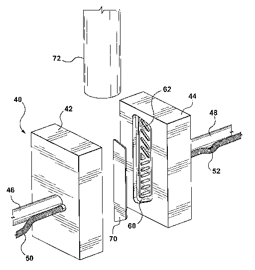
reference to Figures 4 through 11. Figure 4 illustrates diagrammatically the
blow molding mold 40. The blow molding mold comprises a first mold half or
component 42 and a complimentary mold half or component 44.
Diagrammatically, the mold halves 42 and 44 are shown as being movable
toward and away from each other by rams 46 and 48 respectively. The mold
halves 42 and 44 each have supply conduits 50 and 52 respectively. The
supply conduits 50 and 52 supply cooling fluids as need be. In addition, the
supply conduit 52 also includes a source of vacuum pressure as will be
explained more fully below.
[0026] The mold halves 42 and 44 each include a mold cavity. tn the
view illustrated in Figure 4, only the cavity 60 within mold half 44 is
visible.
The mold cavity 60 determines the shape of a portion of the running board
and includes the necessary configuration to mold a substantial portion if not
all of the support surface 30. The mold cavity 60 within the mold half 42 also
includes a subcavity 62. The subcavity 62 includes a configuration for molding
a desired pattern on what will become the upper surface of a step pad.
[0027] In accordance with this aspect of the invention, a process
includes providing a moldable step pad 70 and the extrusion of a parison 72.
The parison 72 may be extruded from a well known extrusion head.
[0028] Figure 5 illustrates the movement of the step pad 70 to a
position between the mold halves 42 and 44. Figure 6 illustrates the
movement of the moldable step pad 70 into the cavity 60 of the mold half 44.
Figure 7 illustrates the final position of the step plate 70 entirely within
tile
subcavity 62. The movement of the step pad 70 as shown diagrammatically i~n
Figures 4, 5, 6 an 7 can most easily be accomplished using a programmable
robotic arm. A supply of step pads 70 may be located where they -be grasped
CA 02535831 2006-02-14
WO 2005/030469 PCT/CA2004/001645
_6_
and extracted by one or more robot arms. The robot arm moves the moldable
step pad 70 until it is placed within the subcavity 62. 'Once the robot arm
has
placed the movable step pad 70 within the subcavity 82, then vacuum .
pressure, available from supply conduit 52 is applied to the subcavity 62, so
that the moldable step plate 70 is retained and accurately positioned within
the subcavity 62. The robot arm then retracts so that it is no longer located
between the mold halves 42 and 44. When that has been completed, th.e
parison 72 is extruded to extend between the mold halves as shown in
Figures 7 and 8, Figure 8 illustrates the completion of the extrusion of the
parison and the mold halves are now ready to be closed about the parison.
[0029] Figure 9 illustrates the closure of the mold halves 42 and 44 to
form a closed blow mold ready for application of a blow molding gas under .
appropriate pressure.
[0030] In this embodiment of the invention, the moldable step plate ,70
is made from a material which may be thermal formed within the mold 42 and
which is compatible with the material of the parison 72 so that the materials
may fuse together to form an integral structure under suitable pressure and
temperature.
[0031] The vacuum pressure applied to the submold 62 is intended
primarily to hold the moldable step plate 70 in place. If the moldable step
plate
has not been raised to a temperature close to its molding temperature, no
substantial molding of the step plate 70 will occur under the vacuum force
alone. However, when the blow molding gas is supplied to the interior-of the
parison 72, the parison is at a moldable temperature and the parison will then
expand within the mold 40. As the parison expands, a portion of the parison
will then come into contact with the moldable step plate 70. This will result
in
the transfer of heat from the wall of the parison to the moldable step plate
70.
In addition, as the parison 72 continues to expand, it will deliver
substantial
pressure to the moldable step plate 70 and forcing it against the pattern
included within the subcavity 62.
CA 02535831 2006-02-14
WO 2005/030469 PCT/CA2004/001645
-7-
[0032] Preferably the blow molding pressure is substantial. Most
preferably the blow molding pressure may be at or above 90 psi. .
[0033] The moldable step plate 70 as illustrated in Figure 4, is a
relatively thin strip of moldable plastic. The strip of plastic may be of the
order
of one to one and a half millimeters thick. The subcavity 62 is preferably
less
deep than the thickness of the strip. Preferably for a strip having a
thickness
of one to one and a half millimeters, the cavity may be of about one half
millimeter depth. This means that upon completion of the molding, the step
will project upwardly from the formed surface 30 by approximately one half
millimeter or more, while the remainder of the step plate will be below and
integrated into the wall of the parison. This is illustrated in Figure 2.
[0034] After the blow molding pressure is released, in typical blow
molding fashion, the mold 40 is cooled and opened. The opened mold is
shown diagrammatically in Figure 10 with the running board assembly 2~
being shown having been ejected from the mold halves ready for trimming.
[0035] After ejection of the molded running board assembly 20, the
running board assembly~is trimmed as desired and removed from the mold.
This is shown in Figure 11.
[0036] The running board assembly 20 shown in Figure 1 includes a
step pad 24. The step pad 24 is incorporated into the running board assembly
10 by means of thermal fusion between the step pad 24 and the running
board 22 which occurs during the blow molding process. In accordance with
an alternate aspect of the invention, the step pad need not be comprised of a
moldable material nor a material that will thermally fuse with the material of
the running board.
[0037] Figure 12 illustrates a step pad 124. The step pad 124 is a metal
strip. The metal strip includes a raised pattern 125 on one surface and at
least
one and preferably a plurality of longitudinally extending tCey shaped ribs
128
on the other surface.
CA 02535831 2006-02-14
WO 2005/030469 PCT/CA2004/001645
_$_
[0038] ~ Figure 13 illustrates in cross-section, a running board assembly
120. The running board assembly 120 includes the step pad 124 which has
been incorporated during blow molding into a running board 122.
[0039] The process for manufacturing the running board assembly 120
illustrated in Figure 12 and 13 is similar to the process illustrated in
Figures 4
through 11. In accordance with this aspect of the invention, the metal step
pad
124 is placed within a subcavity 162 within one mold half 144 of a mold 140.
[0040] The step pad 124 may be obtained from a storage location and
placed into the subcavity 162 by a computer controlled robot arm. Once the
step pad 124 is placed within the subcavity 162, then vacuum pressure is
applied to the subcavity 162 holding the step pad in place.
[0041] Once the step pad is held in place by the vacuum pressure, then
a parison 72 is extruded between the mold halves 42 and 144, the mold is
closed and a blowing pressure is applied to the interior of the parison. As
the
parison expands under the blowing pressure, a portion of the wall of th.e
parison will encounter the surface of the step pad 124 which includes the
plurality of key shaped ribs 128. The raised portions 125' of the step pad 124
will bear against the surface of the subcavity 162.
[0042] With reference to Figure 13, it will be observed, that as the wall
of the parison is forced under blowing pressure against the ribs 128, a
portion
of the wall will flow around the ribs. Each rib is substantially key-shaped.
By
this, it is meant that the portion of the rib which becomes embedded in the
wall of the parison has an undercut or smaller width. In a preferred
embodiment of the invention as shown in Figure 13, the ribs are T-shaped.
When the wall of the parison solidifies as the mold is cooled, then the cooled
plastic of the parison wall extends into the undercut or thinner region of the
rib
thereby permanently incorporating the step pad .124 into the running board
120 as the running board is formed. Thus, when the mold opens, the part
which is ejected is the running board assembly 120 with an integrated step
pad 124.
CA 02535831 2006-02-14
WO 2005/030469 PCT/CA2004/001645
_g_
(0043] Reference is now made to Figures 1, 2, 3 and.15. As shown, the
running board assembly 20 includes a trim strip 26. The trim strip may be a
moldable plastic which can thermally fuse with the parison 70 as the running
board 22 is formed. Alternatively, the trim strip 26 may be manufactured from.
a material which does not thermally fuse with the running board 20. In this
regard, the trim strip 26 may be a metallic strip similar to the step pad 124.
(0044] The trim strip 26 is in the form of an insert which may be
positioned within a mold half 43 in a manner analogous to the step pad 70 or
the step plate 124. In order to accomplish this, there may be a separate
subcavity 263. The subcavity 263 may either be in the same mold half as the
subcavity 62 or in the other mold half. While the trim strip 26 may use a
similar retention means as the ribs 128 of step pad 124, an alternate
retention
system is shown in the enlarged view of Figure 3 and 15.
(0045] The subcavity 263 into which the trim strip 26 may be placed
and retained by vacuum pressure advantageously includes an undercut 264
extending around the perimeter of the subcavity 263. The running board
assembly. including both the step pad 24 or a step pad 124 and one or more
trim strips 26, may be formed using the process discussed in connection with
Figures 4 through 11. As the wall of the parison is expanded toward the trim
strip 26, material from the parison will be forced against the surface of the
trim
strip 26. Under the blowing pressure, a small portion 80 of the parison
material will be forced into the undercut. That portion of the parison then is
adjacent the other surface of the trim strip 26. Sufficient length of undercut
along the perimeter of the subcavity containing trim strip 26 is provided so
that
upon completion of the molding process, the trim strip 26 is permanently
retained in the running board assembly ,20. Most preferably, the undercut
extends substantially around the perimeter of the subcavity so that in effect,
the portion 80 of the parison material flows around substantially all of the
perimeter edge of the trim strip 26. This in effect provides a permanent
picture
frame type retention of the trim strip 26.
CA 02535831 2006-02-14
WO 2005/030469 PCT/CA2004/001645
- 1fl -
[0046] The trim strip ~6 is retained by the cooled material of the
parison. 'Thus, the trim strip 26 may be manufactured from any desirable
material which would include metals or plastics which are not compatible with
the material of the running board 22 or materials which are compatible with
the material of the running board 22.
[0047] As has been explained above, there are various aspects of
preferred embodiments of the invention. The above description is to be taken
as illustrative only with the full scope of the invention to be determined
from
reference to the following claims.