Note : Les descriptions sont présentées dans la langue officielle dans laquelle elles ont été soumises.
CA 02535844 2008-05-23
SIMPLIFIED SCRAMBLING SCHEME
FOR SATELLITE BROADCASTING SYSTEMS
BACKGROUND OF THE INVENTION
1. Field of the Invention
The present invention relates generally to methods and systems for scrambling
transmitted information, and more specifically, to a simplified scrambling
scheme that
unifies all signals with a common reference phase.
2. Description of the Related Art
Digital Direct Broadcast Systems (DBS), such as DIRECTV , which is
provided by the assignee of the present invention, have become very
successful.
However, as such systems evolve, there is an increasing demand for additional
bandwidth to carry an ever-increasing set of audio, video and data services.
In satellite television, there is a constant need for additional throughput to
adequately accommodate the ever-increasing demands with respect to the video
and
data services which they provide. With respect to developing their next
generation
systems, more efficient forward error correction (FEC) codes such as low-
density
parity check (LDPC) codes, turbo codes, etc., are under investigation in order
to
achieve the aforementioned goal. To use these highly efficient FEC codes, a
frame
header is pre-inserted to modulated data to ensure that the boundaries of code
frames
can be easily identified by the decoder. Also, since these codes are often
operated
over channels with very low carrier-to-noise ratio (CNR) and in the presence
of low
noise block (LNB) and other phase noise, .pilot symbols are inserted
periodically to
improve the performance of carrier synchronization.
Header and pilot symbols are essential in the next generation of satellite
television broadcasting systems to ensure the quality of timing acquisition
and frame
synchronization as well as carrier (including frequency and phase) acquisition
and
CA 02535844 2011-07-18
tracking. There is a need to improve demodulation performance of systems with
header/pilot symbols. The present invention satisfies this need.
SUMMARY OF THE INVENTION
To address the requirements described above, the present invention discloses a
method and apparatus for scrambling symbols in a data transmission system,
comprising scrambling all elements of a frame (frame header, frame body and
one or
more pilot symbols) prior to transmission of the frame by the system, so that
all of the
elements have a common reference phase. The present invention results in
simplification and increased flexibility of the receiver front-end design
without
affecting the overall system performance. In many current communications
systems
with frame header/pilot symbols, the phases of header/pilot symbols are not
designed
to be aligned with any constellation points. This scheme is novel from the
viewpoint
of signal design: it takes into account possible impacts due to irregular
phase changes
between header/pilot symbols and modulated data.
According to an aspect of the invention, there is provided a method of
generating a scrambled signal in a data transmission system, the scrambled
signal
having frames comprising real symbols h k and imaginary symbols QS ,k from a
signal having real symbols Ik and imaginary symbols Qk , comprising the steps
of:
generating a real part of a k`h element of a complex scrambling sequence
(dl_k );
generating an imaginary part of the k'h element of the complex scrambling
sequence (dr, k );
generating a scrambling phase multiplier nk according to:
nk = 2d, k + dQ k ; and
generating the scrambled signal:
i(2'rnk
IS,k + JQS,k = (Ik + JQk)e I\ 4
2
CA 02535844 2011-07-18
According to a further aspect of the invention, there is provided an apparatus
for generating a scrambled signal having real symbols I,,, and imaginary
symbols
Qs,k from a signal having real symbols Ik and imaginary symbols Qk ,
comprising:
means for generating a real part of a k`" element of a complex scrambling
sequence (d,,, );
generating an imaginary part of the k"' element of the complex scrambling
sequence (dQ.k );
means for generating a scrambling phase multiplier nk according to:
nk = 2d, k + dQ,k ; and
means for generating the scrambled signal:
2nnk
k k + JQ.S,k = (I k + jQk)e
According to a further aspect of the invention, there is provided an apparatus
for scrambling symbols in a data transmission system, comprising:
means for scrambling all elements of a frame prior to transmission of the
frame by the system so that all of the elements have a common reference phase,
comprising:
means for performing a complex scrambling operation according to:
((
IS,k + jQS,k = (Ik + JQkexp{I 2~znk
4
wherein:
Ik,Qk represents original symbols,
I,'.,k,QS,k represents scrambled symbols,
nk represents a scrambling phase multiplier, such that nk = 2d, .k + dQ,k ,
and
2a
CA 02535844 2011-07-18
d,,k and de k are real (I) and imaginary (Q) components of a k"element of
the complex scrambling sequence.
According to a further aspect of the invention, there is provided a method of
scrambling symbols in a data transmission system, comprising:
scrambling all elements of a frame prior to transmission of the frame by the
system so that all of the elements have a common reference phase, comprising:
performing a complex scrambling operation according to:
I'S .k + 1Qs,k = (1k + jQk) "exp 2;rnk
j 4
wherein:
Ik,Qk represents original symbols,
Is,k,Qs,k represents scrambled symbols,
nk represents a scrambling phase multiplier, such that nk = 2d, k + dQ,.k ,
and
di k and dQ k are real (1) and imaginary (0) components of a k`h element of
the complex scrambling sequence.
According to another aspect of the invention, there is provided a method of
scrambling a frame in a data transmission system, said frame having a header
and a
body, the header being data modulated according to a first modulation having a
header signal constellation with header signal points and the body comprising
a pilot
symbol having a phase, and body data modulated according to any of a plurality
of
second modulations having a plurality of body signal constellations, with body
signal
points, the method comprising:
aligning the pilot symbol of the unscrambled body in phase at it/4 with a
header signal point of the header signal constellation, wherein the pilot
symbol of the
unscrambled body is aligned in phase at t/4 with at least one body signal
point of
each of the plurality of body signal constellations, wherein the first
modulation is it/2-
BPSK and the plurality of second modulations are one selected from the group
2b
CA 02535844 2011-07-18
comprising BPSK, QPSK, 8PSK, 16APSK and 32APSK, and wherein the scrambling
means performs a complex scrambling operation according to:
I S,k + JQS,k = I k + JQk) . exp .J 2,7n,
4
wherein:
Ik,Qk represents original symbols,
I .k I Qs,k represents scrambled symbols,
nk represents a scrambling phase multiplier, such that nk = 2d, ,k + dQ k ,
and
d, k and dc,_k are real (1) and imaginary (Q) components of a kt1i element of
the complex scrambling sequence.
According to another aspect of the invention, there is provided a system for
scrambling a frame in a data transmission system, said frame having a header
and a
body, the header being data modulated according to a first modulation having a
header signal constellation with header signal points and the body comprising
a pilot
symbol having a phase, and body data modulated according to any of a plurality
of
second modulations having a plurality of body signal constellations, with body
signal
points, the system comprising:
the pilot symbol of the unscrambled body being aligned in phase at 7U/4 with a
header signal point of the header signal constellation, wherein the pilot
symbol of the
unscrambled body is aligned in phase at 7r/4 with at least one body signal
point of
each of the plurality of body signal constellations, wherein the first
modulation is 7C/2-
BPSK and the plurality of second modulations are one selected from the group
comprising BPSK, QPSK, 8PSK, 16APSK and 32APSK, and wherein the scrambling
means performs a complex scrambling operation according to:
IS,k+JQS,k =(Ik+IQk).exp j 2nnk
4
wherein:
Ik,Qk represents original symbols,
IS,k'QS.k represents scrambled symbols,
2c
CA 02535844 2011-07-18
nk represents a scrambling phase multiplier, such that nk = 2d, ,k + do, k ,
and
d,,k, and d, k are real (I) and imaginary (Q) components of a k`1 element of
the complex scrambling sequence.
BRIEF DESCRIPTION OF THE DRAWINGS
Referring now to the drawings in which like reference numbers represent
corresponding parts throughout'.
FIG. 1 is a diagram illustrating an exemplary direct broadcast satellite
system
according to a preferred embodiment of the present invention;
2d
CA 02535844 2006-02-14
WO 2005/022758 PCT/US2004/027981
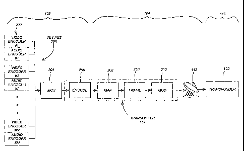
FIG. 2 is a block diagram that further illustrates an exemplary signal
transmission system according to the preferred embodiment of the present
invention;
FIG. 3 is a block diagram that further illustrates an exemplary signal
reception
system according to the preferred embodiment of the present invention;
FIG. 4 is a schematic that illustrates the format of the physical layer (PL)
frame;
FIG. 5 is a block diagram indicating a Complex Scrambling Sequence
Generation circuit according to a preferred embodiment of the present
invention;
FIG. 6 shows the constellations of scrambled signals with { 45 , 135 }
rotations according to a preferred embodiment of the present invention;
FIG. 7 shows the constellations of scrambled signals with {0 , 90 , 180 }
rotations according to a preferred embodiment of the present invention; and
FIG. 8 is a flowchart that illustrates the logic performed in the preferred
embodiment of the present invention.
DETAILED DESCRIPTION OF THE PREFERRED EMBODIMENT
In the following description of the preferred embodiment, reference is made to
the accompanying drawings which form a part hereof, and in which is shown by
way
of illustration a specific embodiment in which the invention may be practiced.
It is to
be understood that other embodiments may be utilized and structural changes
may be
made without departing from the scope of the present invention.
Overview
The present invention describes a simplified scrambling scheme that unifies
all
signals in a data transmission system, such as a direct broadcast satellite
system,
including frame header, frame body, and pilot symbols, with a common reference
phase. This results in the simplification and increased flexibility of the
receiver front-
end design without affecting the overall system performance.
3
CA 02535844 2006-02-14
WO 2005/022758 PCT/US2004/027981
In many current communications systems with frame headers and pilot
symbols, the phases of the frame headers and pilot symbols are not designed to
be
aligned with any constellation points for modulated data (i.e., the frame
body). The
scheme of the present invention is novel from the viewpoint of signal design:
it takes
into account possible impacts due to irregular phase changes between the frame
headers/pilot symbols and modulated data.
The present invention provides a simple scrambling scheme that results in the
following advantages over that proposed by the DVB-S2 (Digital Video
Broadcasting
- Satellite Version 2) standards group:
= Eliminates unnecessary phase jumps between frame header/pilot
symbols and modulated data: the spectral properties of modulated data
are preserved.
= Requires less signal processing: Only I/Q (in-phase and quadrature)
component swapping and sign changes are needed and re-scaling is not
required.
= Reduces the implementation complexity of the receiver: frame
headers/pilot symbols can be treated as modulated data; i.e., no special
treatment is required for frame headers/pilot symbols.
= Allows more choices with respect to acquisition/tracking algorithms:
no performance degradation is experienced with respect to the
acquisition/tracking algorithms based on averaging or Nth' power
nonlinear operation.
Direct Broadcast Satellite System
FIG. 1 is a diagram illustrating an exemplary direct broadcast satellite
system
100 according to a preferred embodiment of the present invention. The system
100
includes a control center 102 operated by a service provider in communication
with
an uplink center 104 via a link 106 and with receiving stations 108 via a link
110.
The control center 102 provides broadcast materials to the uplink center 104
and
4
CA 02535844 2006-02-14
WO 2005/022758 PCT/US2004/027981
coordinates with the receiving stations 108 to offer various services,
including key
management for encryption and decryption, etc.
The uplink center 104 receives the broadcast materials from the control center
102 and, using an antenna 112 and transmitter 114, transmits the broadcast
materials
via uplink 116 to one or more satellites 118, each of which may include one or
more
transponders 120. The satellites 118 receive and process the broadcast
materials and
re-transmit the broadcast materials to receiving stations 108 via a downlink
122, using
transponders 120. Receiving stations 108 receive the broadcast materials from
the
satellites 118 via an antenna 124, and decode and decrypt the broadcast
materials
using a receiver 126.
Signal Transmission
FIG. 2 is a block diagram that further illustrates an exemplary signal
transmission system according to the preferred embodiment of the present
invention.
The control center 102 includes a plurality of video and/or audio encoders 200
that
each encode a video and/or audio source into a video elementary stream (VES)
and/or
audio elementary stream (AES) 202. The resulting video and/or audio elementary
streams 202 are statistically multiplexed at 204. The multiplexed data stream
is
encoded using a forward error correcting (FEC) code at 206. After FEC
encoding, a
number of transmitter 114 functions are performed. The encoded data stream is
mapped into the desired constellation, i.e., BPSK (binary phase shift keying),
QPSK
(quadrature phase shift keying), 8PSK (8 phase shift keying), 16APSK (16
amplitude
phase shift keying), or 32APSK (32 amplitude phase shift keying), at 208, and
physical layer (PL) framing is performed at 210, wherein the PL framing
includes the
addition of a frame header, the optional insertion of pilot symbols, and the
scrambling
or randomization of the frame body. The data stream of PL frames is modulated
and
converted to uplink frequency at 212, and then uplinked via antenna 112 to one
or
more transponders 120 in one or more satellites 118.
5
CA 02535844 2006-02-14
WO 2005/022758 PCT/US2004/027981
Signal Reception
FIG. 3 is a block diagram that further illustrates an exemplary signal
reception
system according to the preferred embodiment of the present invention. At the
receiving stations 108, the data stream of PL frames is downlinked from the
transponders 120 in the satellites 118 via antenna 124 and receiver 126. In
the
receiver 126, the signal stream is frequency down-converted and the data
stream is
demodulated at 300. After demodulation, PL de-framing is performed on the data
stream at 302, which includes de-scrambling, and synchronization to and
removal of
the frame header and optional pilot symbols to recover the frame body. The
data
stream is de-mapped at 304 to recover the FEC encoded data stream. The FEC
encoded data stream is decoded at 306. The resulting data stream is
statistically
demultiplexed at 308 to recover the video and/or audio elementary streams 310.
The
video and/or audio elementary streams 310 are decoded by video and/or audio
decoders 312, respectively, to complete the signal reception.
Physical Layer Frame
FIG. 4 is a schematic that illustrates the format of the physical layer (PL)
frame 400. Every PL Frame 400 is comprised of.
= a PL Body 402, comprised of a payload of 64,800 bits (long FEC
frame) or 16,200 bits (short FEC frame), generated by encoding the
user bits according to the selected FEC scheme; and
= a PL Header 404, containing a synchronization sequence, type of
modulation and FEC rate, frame length, and presence/absence of pilot
symbols.
The PL Body 402 is comprised of S slots 406, wherein each slot is comprised
of 90 symbols. The number S of slots 406 varies depending on the modulation,
wherein S=720 for BPSK, S=360 for QPSK, S=240 for 8PSK, S=180 for 16APSK
and S=90 for 32APSK. Pilot symbols 408 may be inserted every 16 slots to
maintain
synchronization, wherein the Pilot symbols 408 comprise 36 symbols.
6
CA 02535844 2006-02-14
WO 2005/022758 PCT/US2004/027981
The PL Header 404 is comprised of 90 symbols with a fixed 7r/2 BPSK
modulation. The first 26 symbols in the PL Header 404 allow detection of Start
Of
Frame (SOF). The next 64 symbols comprise a Physical Layer Signalling Code
(PLSCODE), suitable for soft-decision correlation decoding and containing the
signaling information listed above.
In the original DVB-S2 signal phasing structure, each PL Header 404 is
modulated using t/2 BPSK (0 , 180 , and 90 ). Each PL Body 402 is randomized
for energy dispersal by performing a complex scrambling operation at 410 by
multiplying (I+jQ) samples of the PL Body 402 by a complex scrambling
(randomization) sequence 412, represented by (Ci+j CQ).
Original DVB-S2 Complex Scrambling Operation
In the original DVB-S2 signal phasing structure, the complex scrambling
operation performed on the PL Body 402 comprises the following:
IS,k+JQS,k= 1 [](Ik + JQk) -(CI,k+CQ,k)
wherein:
Ik,Qk represent original symbols,
Is,k'Qs,k represent scrambled symbols, and
CI k, CQ,k represent the complex scrambling sequence 412 with values +1.
The complex scrambling sequence 412 is derived from:
C1 'k = (-1) dl.k
dQ.k
CQ k = (-1)
wherein dI k and dQ k are real (I) and imaginary (Q) components of a k"`
element of
the complex squaring sequence 412 generated by a Complex Scrambling Sequence
Generation circuit 500 shown in FIG. 5 and described in more detail below.
7
CA 02535844 2006-02-14
WO 2005/022758 PCT/US2004/027981
Note that the complex scrambling operation 410 comprises simple additions
and subtractions excluding the 1 / factor, according to the following table:
CI,k CQ,k IS,k + JQS,k
1 1 (Ik -Qk)+J(Ik +Qk)
1 -1 (Ik -Qk)+J(-Ik +Qk)
-1 1 (-Ik -Qk)+Ark -Qk)
-1 -1 (-Ik +Qk)+J(-Ik -Qk)
After applying the above rule, the resulting signal phasing structure is as
follows:
= PL Header 404 modulated with ir/2 BPSK (0 , 180 , and 90 ),
= Modulated data (i.e., PL Body 402) scrambled with rotations of 45
or 135 :
^ BPSK is rotated to diagonal axes ( 45 and 135 ),
QPSK is rotated to the I and Q axes (0 , 90 , 180 ),
^ 16APSK and 32APSK are rotated with node concentration on I
and Q axes, and
^ the 8PSK constellation is unchanged.
The original signal constellations for several modulations are shown in FIG.
6,
which is described in more detail below. The upper and lower rows represent
the
constellations before and after scrambling by the above rule, respectively.
The dots
represent constellation nodes, and the arrows represent pilot symbol phases.
The PL
Header 404 nodes are not affected by the scrambling. It can be seen that the
phases of
PL Header 404 and Pilot symbols 408 are not always aligned with those of the
signal
constellations for the modulated data, i.e., the PL Body 402. Specifically,
the phase
of the Pilot symbols 408 is 0 before scrambling, but is misaligned with
respect to
QPSK, 8PSK and 16APSK constellations after scrambling. Hence, phase jumps
8
CA 02535844 2006-02-14
WO 2005/022758 PCT/US2004/027981
between a PL Header 404 / Pilot symbols 408 and the PL Body 402 can be readily
observed in the constellations.
The present invention, on the other hand, unifies all signals with a common
reference phase by means of an improved complex scrambling operation.
Improved Complex Scrambling Operation
The present invention is intended to make the phases of the PL Header 402
and Pilot symbols 408 align with some points of constellations of the PL Body
402 as
modulated. This can be accomplished by performing an improved complex
scrambling operation 410 on PL Body 402 and Pilot symbols 408:
'S,k +jQs,k - (Ik +JQk).eXp{j2TCnk
4
wherein:
Ik,Qk represents original symbols,
Is,k I Qs,k represents scrambled symbols,
Ilk represents a scrambling phase multiplier, such that nk = 2d[,k + dQ k ,
and
dI k and dQ k are real (I) and imaginary (Q) components of a k`0' element of
the complex scrambling sequence 412 generated by the circuit 500.
In this complex scrambling operation 410, only I/Q component swapping and
sign changing are performed, which is described in the following table:
dI k dQ k nk Rotation 'S,k + jQS,k
0 0 0 00 Ik +JQk
0 1 1 90 -Qk + jIk
1 0 2 180 -Ik - JQk
1 1 3 270 Qk - ilk
9
CA 02535844 2006-02-14
WO 2005/022758 PCT/US2004/027981
Note that rescaling is not required.
According to the present invention, the resulting signal phasing for example
modulations is summarized as follows:
= BPSK payload symbol phases = {45 , -135 }
- Scrambled symbol phases = { 45 , 135 }
= 8PSK payload symbol phases = {0 , 90 , 180 , 45 , 135 }
Scrambled symbol phases = {0 , 90 , 180 45 , 135 }
(same set)
= PL Header 402 symbol phases = {45 , -135 } (same as BPSK)
- 't/2-Modulated data phases = { 45 , 135 }
= Pilot symbol 408 phases = {45 }
Scrambled symbol phases = { 45 , 135 }
= All signals have a common phase of 45 with respect to BPSK, QPSK,
8PSK, 16APSK and 32APSK modulations, before as well as after the
complex scrambling operation 410 is performed.
The constellations of various modulations from the present invention are
shown in FIG. 7, which is described in more detail below. Note that there is
no
unnecessary phase jump between the PL Header 404 and Pilot symbols 408, and
the
modulated data, i.e., PL Body 402, in the present invention.
Complex Scrambling Sequence Generation Circuit
FIG. 5 is a block diagram indicating a Complex Scrambling Sequence
Generation circuit 500 used in the preferred embodiment of the present
invention.
Generally, the functions of the Complex Scrambling Sequence Generation circuit
500
would be performed in the framing block 210 of the transmitter 114 and the de-
framing block 302 of the receiver 126.
Within the circuit 500, two sequences of 1-bit delays (labeled as "D") are
provided: a first sequence of X delays 502 (labeled left to right as X(17) to
X(0)) and a
second sequence of Y delays 504 (labeled left to right as Y(17) to Y(O)).
CA 02535844 2006-02-14
WO 2005/022758 PCT/US2004/027981
A initial string of bits or conditions are loaded into the first and sequence
of
delays 502 and 504, wherein the initial string of bits or conditions comprise:
X(0)=1,X(1)=X(2)=...=X(17)=0
Y(0) = Y(l) = Y(2) _ ... = Y(17) =1
Thereafter, the PL Body 402 is loaded bitwise into the Complex Scrambling
Sequence Generation circuit 500 at delay X(0), wherein the bits in each of the
delays
are loaded into the next adjacent delay upon each clock, so that:
X(0)=X(1)=X(2)=...=X(17)
Y(0) = Y(1) = Y(2) = ... = Y(17)
In addition, a number of other operations are performed using various outputs
of the delays. For example, an exclusive OR (XOR) 506 generates an output
value of:
dr,k =X(0)+Y(0)
This output value is then used at 508 to generate an output value for the
circuit
500 according to the following:
CI 'k = (_1)dl.k
An XOR 510 generates an output value of:
X(4) + X(6) + X(14)
An XOR 512 generates an output value that is used as the input to X(17):
X(17) = X(0) + X(7)
An XOR 514 generates an output value that is used to set the value of Y(17):
Y(17) = Y(0) + Y(5) + Y(7) +Y(10)
An XOR 516 generates an output value of:
Y(5) + Y(6) + Y(8) + Y(9) + Y(10) + Y(11) + Y(12) + Y(13) + Y(14) + Y(15)
An XOR 518 generates an output value of:
dQ k = XOR516 + dl,k
11
CA 02535844 2006-02-14
WO 2005/022758 PCT/US2004/027981
This output value is then used at 520 to generate an output value for the
circuit
500:
CQ,k = (-1)dQ.k
Constellations of Scrambled Signals using DVB-S2 Scrambling
FIG. 6 shows the constellations of signals using the existent DVB-S2
scrambling scheme. The upper level constellations 600 indicate the signals
before
scrambling for each of the different modulations, while the lower level
constellations
602 indicate the signals after scrambling for the PL Header 404 as well as for
each of
the different modulations. The arrows 604 identify the rotations of the Pilot
symbols
408.
Constellations of Scrambled Signals using Improved Scrambling
FIG. 7 shows the constellations of signals using the improved scrambling
scheme of the present invention. The upper level constellations 700 indicate
the
signals before scrambling for each of the different modulations, while the
lower level
constellations 702 indicate the signals after scrambling for the PL Header 404
as well
as for each of the different modulations. The arrows 704 identify the
rotations of the
Pilot symbols 408.
Logic of the Preferred Embodiment
FIG. 8 is a flowchart that illustrates the logic performed in the preferred
embodiment of the present invention. Specifically, the logic comprises a
method of
generating a scrambled signal having real symbols Is k and imaginary signals
Qs,k
from a signal having real symbols Ik and imaginary symbols Qk.
Block 800 represents the step of generating a real part of a k"' element of a
complex scrambling sequence (d, k ).
12
CA 02535844 2006-02-14
WO 2005/022758 PCT/US2004/027981
Block 804 represents the step of generating a scrambling phase multiplier nk
according to:
nk=2dlk+dQk.
Block 806 represents the step of generating the scrambled signal:
i (2nn,; )
Is,k +JQs,k = (Ik + JQk)e r 4JJ
Performance
The present invention provides performance at a level that is no less than
that
seen in the original DVB-S2 scheme in terms of carrier and phase acquisition
as well
as carrier and phase tracking. In fact, the present invention provides
distinct
advantages over the original DVB-S2 scheme in that it eliminates unnecessary
phase
jumps of 7t/4 and n/8 between the PL Header 404 and PL Body 402, between the
Pilot
symbols 408 and PL Body 402, and between nodes from different modulations,
i.e.,
different PL Bodies 402. Such phase jumps may be undesirable in terms of
performance as they may impact Nth power processing performance, etc.
Furthermore, the present invention requires less processing as only I/Q
component
swapping and sign changes are needed and rescaling is not required. Finally,
the
present invention simplifies the DVB-S2 specification as it reduces design and
implementation complexity and associated testing and reduces cost for both the
transmitter and the receiver.
Conclusion
The foregoing description of the preferred embodiment of the invention has
been presented for the purposes of illustration and description. It is not
intended to be
exhaustive or to limit the invention to the precise form disclosed. Many
modifications
and variations are possible in light of the above teaching.
It is intended that the scope of the invention be limited not by this detailed
description, but rather by the claims appended hereto. The above
specification,
13
CA 02535844 2006-02-14
WO 2005/022758 PCT/US2004/027981
examples and data provide a complete description of the manufacture and use of
the
apparatus and method of the invention. Since many embodiments of the invention
can be made without departing from the scope of the invention, the invention
resides
in the claims hereinafter appended.
14