Note : Les descriptions sont présentées dans la langue officielle dans laquelle elles ont été soumises.
CA 02536707 2006-02-15
INTEGRATED CONTINUOUS MEAT PROCESSING SYSTEM
FIELD OF THE INVENTION
The invention relates to a method and apparatus for processing meat which may
include a
control system.
BACKGROUND OF THE INVENTION
In commercial systems for making certain processed meat products such as
bologna and hot
dogs, raw meat in the form of chunks or pieces and other ingredients such as
spices are ground,
chopped and/or otherwise blended with one or more salt solutions or brine to
provide a mixture that
can subsequently be formed into a stable meat emulsion or protein matrix.
Similar steps of grinding,
chopping and/or otherwise working are also employed in making coarse ground
products such as
sausages, whole muscle products such as processed ham and processed turkey,
and other processed
meat products. In each case, protein forms a matrix to hold or bond the
separate pieces together.
A stable protein matrix requires the protein bonds to suspend or bond with fat
and water.
Creation of protein bonds in this context requires a process commonly known as
protein extraction.
In this process, salt soluble or salt-extractable and heat coagulable proteins
such as myosin,
actomyosin, and actin bind water, swell and become tacky as a result of
working or blending of the
meat in the presence of a salt or a salt solution. The proteins are
subsequently set when heated to
create a bond. Other myofibrillar proteins, as well as sarcoplasmic or water
soluble or extractable
proteins, may also play a role in bonding. Salt solutions that may be used in
protein extraction
include, but are not limited to, sodium chloride, sodium pyrophosphate or
diphosphate, potassium
chloride, sodium lactate, and potassium lactate. In protein extraction as
described herein, the
mechanism believed to be primarily responsible for creation of the bonds
involves binding proteins,
salts, fats, and/or water and subsequent swelling of the proteins, rather than
solution of the proteins.
More precisely, it is believed that the salt solution frees bonding sites on
the proteins for bonding
with each other, as well as with water and fat. The particles of the cooked
product are bound to each
other by the proteins to provide integrity to the final meat product.
1
CA 02536707 2006-02-15
As used herein, a stable meat protein matrix refers to a mixture that retains
a large percentage
of its components during further processing, including cooking, and during its
shelf-life as a final
product. For instance, an emulsion is considered stable if less than 2% of the
product weight is lost
due to fat cook-out from the cooking stage. If the protein matrix is unstable,
either it or the final
product will lose excessive quantities of water or fat. An unstable protein
matrix leads to yield loss
and to a final product that is not able to maintain sufficient integrity over
its desired shelf-life.
Conventional batch processing is a lengthy process requiring a number of
discrete steps.
Initially, various meats are provided by a vendor with specified contents.
More specifically, the
meats are provided with a specified protein, fat, and/or water content,
typically a percentage by
weight. A batch sheet is provided to processing plant personnel indicating
what mixture of meats,
water, and additives are to be combined for one of a variety of meat products.
Though purchasing is done outside of the processing plant, the batch sheet is
based on
knowledge of the meats presently on-hand at the plant. However, the batch
sheet often needs to be
adjusted. For instance, a particular vendor may provide meat rated as 70%
protein, while the actual
meat has a slightly different content such as 68% protein. Because the batch
sheet is based on the
purchasing and the meat rating provided by the vendor, the plant personnel
often have to adjust the
meats selected for the meat product based on the formula desired for the final
product. The final
product mixture is carefully controlled. For instance, a particular product,
such as hot dogs, may
have no more than 30% fat by weight. If a particular meat is utilized where
the fat content is greater
than what the batch sheet calls for, the final product may have an excessive
amount of fat. To avoid
this, the plant personnel would increase the protein provided by other meats
to balance the fat
content.
Unfortunately, this is not necessarily a sufficiently precise approach. Each
meat, as well as
each chunk in a batch of meat, may vary significantly from a sample taken and
assumed to be
average. Once the water and other additives are mixed in with the batch, it
may be difficult to alter
the balance. At times, the resulting batch is determined to be inaccurately
mixed, and remedial
procedures must be taken such as mixing the batch in with additional
correction materials. In order
to reduce the likelihood of an imprecise batch, relatively large quantities of
meat are provided for a
2
CA 02536707 2011-01-28
single batch in hopes of minimizing or driving to a mean the composition
deviation resulting from a
meat portion with an aberrational content. A typical amount of a particular
meat for a batch is
approximately 2000 lbs.
Batch processes for blending meat and other ingredients and extracting protein
are well
known. A known method for achieving protein extraction and ingredient blending
for whole muscle
products such as processed turkey and processed ham involves puncturing the
whole muscle meat
with hypodermic type needles, injecting brine through the needles, and using a
batch processor or
mixer to work the meat for approximately 45 minutes under vacuum to remove
air, as discussed
below. For coarse ground and emulsified products, meat is ground and added to
a batch processor
with water, salt solution, spices, and/or other ingredients and worked with or
without vacuum for up
to an hour, or e.g., 15 to 45 minutes.
A large batch mixer may process approximately 6,000-12,000 pounds per hour.
The meat
product constituents including the meats and the additives are combined in the
low shear batch
mixer. This mixing stage typically requires 30-60 minutes of being mixed. It
is during this time that
the constituents are transformed into a mixture that will form a stable
protein matrix.
A stable protein matrix is formed when mixtures for each of whole muscle
products, coarse
ground products, and emulsified products allow the salt solution to reach the
salt-extractable protein.
This process, known as curing, achieves the protein extraction. For whole
muscle products,
injection with needles inserted into the meat chunks to deliver the brine
solution is a
relatively imprecise method for attempting to reduce a distance of the meat
through which the
salt solution must diffuse. The curing stage typically requires 24-48 hours
for satisfactory
diffusion, and the batches are stored in vats placed in coolers for the cure
time. Once the
protein extraction has occurred, the mixture may then be further processed.
Input constituents are calculated to result in a specific quantity of cooked
product. If
excessive water or fat is lost post-mix such as during the cook stage, the
carefully regulated water,
fat, and meat ratios will be off-target. If fat is lost prior to the cook
stage, it often remains in the
machinery or piping through which the mixture is processed. This can result in
down time for the
machinery, likelihood of damaged machinery, and greater labor in cleaning the
machinery.
3
CA 02536707 2006-02-15
Furthermore, cooked emulsified products rely, to some degree, on non-protein
or non-bound
materials to provide the proper texture. The proteins bind to form a matrix
with each other and, in
the absence of sufficient fat or water, these bonds may form a larger,
stronger matrix, which leads the
product to become somewhat rubbery. Conversely, if there is too much water,
the cooked product
may be too soft, and may lack integrity.
As used herein, the term additives may refer broadly to brine solution, water
without salt, a
spice slurry, nitrite, or other additives. Though the brine solution and the
meats themselves each
include water, the balance for the final product is typically adjusted with a
quantity of water. The
spice slurry provides, for instance, flavorings. One additive is typically
nitrite which is used as a
preservative and to provide a desired color. Other inert additives, such as
corn starch or non-
functional proteins, may also be included.
As the mixture constituents are churned in the mixer for up to an hour,
contact with air may
produce a froth on the surface of the meat pieces. A final product having
visible air may be
unacceptable. In some cases, the product must be re-processed and mixed in
with subsequent
batches. Air in the product may appear as surface bubbles, or as surface
holes. Entrapped air may
also lead to product swelling during cooking, or may lead to the product
having visible air bubbles
within its interior.
Air affects the product in other ways, as well. For instance, some proteins
are denatured by
the presence of air, which reduces the functionality of the meat for binding
fat and water. The air can
also react with the nitrite to retard the development of the proper color. The
resulting color may then
be undesirable or objectionable to consumers.
To avoid air being stirred into the mixture, vacuum pressure may be applied
during the
mixing process. This requires an extensive set up including the vacuum itself
and seals to maintain
the pressure. The vacuum system and seals require maintenance, and
occasionally leak which results
in downgraded product.
While such mixers have been used commercially for many years, they have
significant
drawbacks. For example, one of the problems is that air may undesirably be
drawn into the product.
Other drawbacks for the mixers include their space requirements and cost due
to their large size,
4
CA 02536707 2006-02-15
labor costs, the length of time required for processing each batch, vat
handling and transfer yield
loss, and the time and expense associated with cleaning of the apparatus.
SUMMARY
The invention relates to improved methods and apparatus for use in making
processed meat
products that provide significant advantages with respect to the size of the
apparatus, the time
required for processing, the control of the process, and/or other aspects of
the manufacturing process.
In one embodiment, a method and apparatus provides for accelerating the
formation of stable
meat mixtures for meat products. Input constituent streams such as meats,
water, salt solution,
spices, and other ingredients are input into a mixer. The constituents are
subjected to high shear
force in the presence of a brine solution. The high shear force distorts the
shape and may reduce the
size of the pieces of meat so that the intimate contact of proteins and salt
solution may occur. The
intimate contact results in effective and efficient protein extraction and
mixing of the constituents in
a relatively brief dwell or mixer-residence time, which may be on the order of
less than a minute. In
this manner, a stable and functional meat protein matrix including extracted
protein is quickly
produced for each of the emulsified products, coarse ground products, and
whole muscle products.
In another embodiment, a method and apparatus are provided for reducing the
time for
ingredient diffusion in the meats. The input constituents including the meats
are worked and
deformed under high shear force so that the protein strands become unraveled
and porous, thus
making them susceptible to infusions of the salt solution and the ingredients.
This results in a
reduced time for processing of the meat while achieving proper dispersion and
diffusion of the
ingredients, including the salt solution necessary for protein extraction.
In accordance with embodiments of the present invention, the preferred
apparatus includes
rotating elements located on at least one rotatable mixing device located
within a housing. Each
mixing device may comprise a plurality of rotating mixing elements such as
paddles, blades or
screws, or may consist of a single element such as a single screw, blade or
paddle. The mixing
devices may be removably supported on one or more shafts. To facilitate
thorough cleaning of the
apparatus without disassembly the elements are preferably integral with their
associated shafts. In
some embodiments, the mixing elements and shaft may be welded together or
formed as a one-piece,
CA 02536707 2006-02-15
unitary machined part.
One mixer in accordance with embodiments of the invention comprises a
plurality of rotating
mixing elements that force some or all of the mixture through one or more gaps
of about 0.08"
between the mixing elements and the interior of the mixer housing, and between
various pairs of
mixing elements, as the mixture advances through the apparatus.
The system preferably achieves sufficient protein extraction, blending, and in
some cases
maceration in less than 5 minutes of processing time, and is believed to be
capable of achieving
sufficient protein extraction, blending and maceration in less than one
minute. In one particular
embodiment, the processing time is about 45 seconds. The average time required
for a given mixture
portion to pass through the processor is about 10-60 seconds. Within that
time, the mixer is capable
of forming ingredients comprising chunks or pieces of raw meat, along with
salt solution, water,
spices, etc., into a mixture that, when cooked, will form a cohesive, self-
supporting processed meat
product without further protein extraction or maceration, also referred to as
a stable protein matrix
that retains a predictable and acceptable amount of fat and water. It should
be noted that for some
products, e.g., bologna and hot dogs, further processing steps may take place
that may incidentally
involve additional protein extraction.
In some embodiments, mixing may take place at pressure equal to or greater
than atmospheric
pressure without the meat mixture suffering from aeration. The constituents
are fed into the mixer,
and the dwell time therein is relatively low. As the mixture is in a
relatively anaerobic environment,
aeration of the mixture does not occur. This eliminates the issues attendant
to air being present in
the meat product, and eliminates the need for a vacuum system for the mixer.
In other embodiments,
the mixing operation may take place in a vacuum environment of, e.g., 25-29
in. Hg vacuum.
In a further embodiment, the process produces low-fat or no-fat emulsified
products with a
texture similar to that of full fat products. The use of high shear processing
for a short period of time
results in a product that does not form the protein structures that impart an
undesirable texture to
typical low or no-fat products. The process may be utilized without the need
to add inert ingredients
or water to impede formation of the protein structures. The meat emulsion
produced forms a stable
emulsion with optimized protein bonding to produce a desired texture.
6
CA 02536707 2006-02-15
The process may avoid formation of a visible protein exudate on whole muscle
and coarse
ground products. The use of high shear processing for a short period of time
assists in eliminating
the exudate from the surface of the meats or meat products. Additionally, the
elimination of a curing
period, as described herein, assists in eliminating the exudate. The protein
exudate does not form
when the meat mixtures are not permitted to stand for a significant period of
time.
The method and apparatus, in some embodiments, utilizes a single piece of
machinery for
low-speed, high-volume grinding, mixing, and emulsification. The single piece
of machinery may
combine initial size reduction, mixing and grinding of the constituents,
protein extraction, and final
emulsification. Continuous processing of the constituents is enabled by such a
system.
In one embodiment, the method comprises feeding a plurality of input food
ingredient
streams comprising one or more meat ingredient streams, measuring at least one
component of at
least one meat ingredient stream, and controlling relative flow rates of the
input food ingredient
streams based on the measurements using a feed forward analysis to maintain a
percentage of at least
one component in the combined stream within a predetermined range. Where two
meat ingredient
streams are employed, they may be differentiated by fat content, with one
having a significantly
higher fat content than the other. In addition to one or more meat ingredient
streams, other input
streams may comprise water, salt solution, spices, preservatives, and other
ingredients, separately or
in combination.
The control system preferably includes at least one in-line analyzer for
measuring a
compositional characteristic of at least one meat input stream and regulating
one or more input flow
rates in response to output data from the analyzer(s). The system may directly
measure a
compositional characteristic such as fat content, or may measure a related
characteristic such as
moisture content from which fat content may be estimated. The control system
may include a
plurality of analyzers in-line for analyzing compositional characteristics of
a plurality of non-
homogeneous input streams. The control system preferably operates one or more
pumps or valves
for each food input stream. Flow may be regulated by varying pump speed, by
intermittent pump
operation, by opening and closing one or more valves, by varying flow rate
with one or more
metering valves, or by other means. The control system thus may control both
the combined flow
7
CA 02536707 2006-02-15
rate and the relative flow rates of the input streams. The relative flow rates
may be adjusted by the
control system based on analysis of the compositional characteristics by the
analyzer.
Feed forward composition analysis may enable rapid adjustment of the flow
rates of the
input streams to enable control of fat content, protein content, moisture
content, and/or other
variables of the combined stream without the need to rely on a feedback loop
based on measurements
of components in the combined stream. By introducing the controlled components
in desired
proportions at the input end, the feed forward control system may also improve
processing time by
eliminating delays associated with adding and mixing additional ingredients to
correct deviations
from desired content levels. The feed forward control system thus may enable a
mixture or blend
having a desired composition to be produced from ingredients introduced at the
input end and
flowing through the processor in a single pass, without recycling any of the
output of the processor.
Another embodiment reduces the necessary number of components of meat
processing
equipment by providing a single, interconnected system. Materials can be
placed in input hoppers or
the like, and each hopper is fed via an input line to the mixer. The input
rates are controlled in a
steady-state manner so that the proper balance of the materials is fed to the
mixer. This control is
done by a system controller which receives the prescribed formulation, such as
the batch sheet data
or formulation rules, for a particular meat product. The system controller is
then able to consider the
composition of the materials in relation to the desired output composition
and, using the desired
formulation for a meat product from the batch sheet, control the pumps, mixer,
and other devices to
meet the formulation. The mixer reduces and combines the incoming materials,
macerates and
mixes them, and effects protein extraction for fat and water binding with the
meat proteins to form a
stable mixture. The mixture can then automatically be passed on for further
processing. The further
processing may be casing or form stuffing, and/or a cook or thermal treatment
stage.
In a further embodiment, the automated and interconnected system may be
utilized as part of
a start-to-finish program for the production of meat products. The control
system can collect and
download the analysis data and the usage data for further analysis. The data
can be examined to
determine an actual input formulation based on the actual composition of each
material or meat used
in the formulation, or the system controller can perform this function and
provide this information to
8
CA 02536707 2006-02-15
a database. This information can be utilized to compare final product yields
to input materials, and
to examine the fat/meat/water ratios of meats for trends including, but not
limited to, specific vendor
trends. Moreover, this information can be used to provide an accurate picture
of the rate of
consumption of various materials, and to allow for effective and precise
ordering of materials.
BRIEF DESCRIPTION OF THE DRAWINGS
Fig. 1 is a schematic representation of a continuous mixing processor in
accordance with an
embodiment of the invention;
Fig. 2 is a perspective view of a mixing apparatus used in an embodiment of
the invention,
shown with a portion of the housing removed;
Fig. 3 is a front elevation view of a component of the apparatus of Fig. 2;
Fig. 4 is a front elevation view of another component of the apparatus of Fig.
2;
Fig. 5 is a front elevation view of another component of the apparatus of Fig.
2;
Fig. 6 is a fragmentary side view of a segment of a rotational element in
accordance with an
embodiment of the invention;
Fig. 7 is a flow diagram representing a process in accordance with an
embodiment of the
invention;
Fig. 8 is a flow diagram representing a process in accordance with an
embodiment of the
invention;
Fig. 9 is a magnified image of a piece of meat showing muscle protein
striation;
Fig. 10 is a magnified image of a piece of meat after a high shear processing
step;
Fig. 11 is a magnified image of a piece of meat after a curing step in the
presence of salt
solution;
Fig. 12 is a magnified image showing a piece of meat after the high shear
processing step in
the presence of salt solution;
Fig. 13 is a table listing configurations of rotational elements for the
apparatus as described
9
CA 02536707 2006-02-15
herein and data relevant thereto;
Fig. 14 is a graphical representation of a measure of emulsion stability for
the configurations
of Fig. 13;
Figs. 15-20 are schematic representations of the configurations of Fig. 13;
and
Fig. 21 is a graphical coordinate representation showing orientations of
components within
the apparatus.
DETAILED DESCRIPTION OF PREFERRED EMBODIMENTS
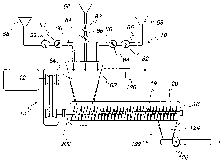
Referring initially to Fig. 1, apparatus for making processed meat products in
accordance
with an embodiment of the invention is shown diagramatically at 10. The
illustrated apparatus
comprises a motor 12 and a belt drive 14 transmitting power to one or more
mixing devices 16
located in a housing 20. Ingredients such as chunks or pieces of meat, one or
more salt solutions,
water, flavorings such as spices, and preservatives are input through input
lines, including pumps 84,
directly into the housing 20. The input line pumps 84 and mixing devices
advance the mixture
through the housing while the mixing device applies a high shear rate to the
mixture to achieve rapid
protein extraction from the meat components. The mixing devices are preferably
made of stainless
steel or another material that is wear resistant and suitable for contact with
food product components.
While a single elongated screw as shown in Fig. 1 may be employed as a mixing
device in
some embodiments, other embodiments employ other types of mixing devices. The
embodiment
illustrated in Fig. 2 employs a twin shaft arrangement with a relatively short
infeed screw 17 used in
combination with a longer array of mixing elements 18 on each shaft 19. As the
ingredients are
forced through the housing 20, the rotating mixing elements 18 macerate and/or
mix the ingredients,
and subject the ingredients to high shear force by driving them between the
mixing elements 18, and
between the mixing elements 18 and interior walls of the housing 20. The
minimum gaps or
clearances between the mixing elements 18 of one shaft 19 and the mixing
elements of a second
mixing device 16, as well as between the mixing elements 18 and the housing
20, are preferably
between 0.06 in. and 0.12 in. In some embodiments, the gaps are 0.08 in. As
the shafts rotate, the
distance between mixing elements 18 on respective shafts will vary so that,
for instance, whole
CA 02536707 2011-01-28
muscle portions may be forced through without being chopped or ground. Forcing
the mixture
through these gaps applies high shear force and results in rapid protein
extraction.
The meat, water, salt solution and other additives such as a spice slurry are
simultaneously
fed into the mixing device. Protein extraction herein involves an intimate
contact between the salt
solution and the salt-extractable proteins and breaking of the meat structure
to separate protein
strands, breaking the protein strands themselves, or unraveling of the
proteins. The mixing device
applying the high shear force mechanically provides this intimate contact, as
opposed to the diffusion
utilized in typical batch processes.
One mechanism for this is simply by reducing the mass transfer or diffusion
distance. By
reducing the meat chunks to relatively, small pieces, the salt solution needs
to diffuse only over a
short distance, if at all. In other words, the work applied to the meat in the
presence of the salt or
brine solution forces the salt solution into the structure of the meat pieces.
This accelerates the
process, thereby promoting the necessary chemical reactions wherein chloride
ions or other ions
occupy bonding sites of the protein strands.
Furthermore, to the degree that the protein stands remain intact, the process
deforms the
meat chunks, which promotes unraveling of the protein strands. Fig. 9 shows a
representative
unprocessed piece of meat under magnification. As can be seen, the meat shows
a regular pattern of
muscle protein striation, the high-density regions of protein being darker.
The inset of Fig. 9 depicts
a portion of the meat piece under greater magnification such that the high-
protein regions can be seen
distinctly separated by regions of low-protein density, or other material such
as fat.
By applying shear force to a meat piece to deforia or grind the meat, the
protein strands are
also deformed, flattened, stretched, and twisted. This opens up the protein
structure, making them
more porous, and promotes penetration of the ingredients, including the brine
solution. As the
dispersion is more thorough, uniform diffusion of the salt solution and other
ingredients and
additives, for instance, is significantly increased by use of the high shear
force. Referring
now to Fig. 10, a representative piece of meat that has been processed with an
apparatus as
described herein in the absence of other constituents or ingredients is shown.
While still
showing a regular pattern of striation, the meat piece has much smaller dark,
high-protein-
density regions, and much wider areas
11
CA 02536707 2006-02-15
of lighter color. In addition, the striation pattern and the dark and light
regions are less distinct,
displaying a somewhat broken structure. In comparison with Fig. 9, it is clear
that the application of
shear force has opened up and made more porous the meat piece. Accordingly,
the meat piece is
more acceptable of or susceptible to diffusion of other ingredients thereinto.
This process causing rapid diffusion through the application of high shear
force eliminates
the need for curing, as has been described as the time for the salt solution
to diffuse through the meat
chunks. Because of the need for curing, typical processing methods are
necessarily batch-oriented.
That is, processing of certain meat products requires diffusion of salt
solution into the meat for
protein extraction to occur. After mixing or injection with salt solution,
typical processes require a
cure or diffusion time for the large meat chunks, during which time the meat
is set aside to allow
satisfactory diffusion. The curing stage required a significant backlog or
meat inventory within the
plant, which is eliminated to allow for just-in-time product usage and
receipt, and reduced storage
needs in the processing plant.
A representative piece of meat that has undergone a static batch process
curing period is
shown in Fig. 11. The piece of meat was injected in conventional manner for
batch processing with
a solution of sodium chloride (NaC1) and allowed to cure for a sufficient
period typical for the meat
type. By comparing the meat piece of Fig. 11 to those of Figs. 9 and 10, the
cured piece of meat
shows a striation pattern and colors similar to that of Fig. 10 wherein the
dark regions are reduced in
size from the unprocessed piece of meat of Fig. 9, and the light regions
showing opened or unraveled
protein with ingredients diffused thereinto.
Through the application of high shear force in the presence of a salt
solution, a meat piece
displays a physical structure combining both the curing and the unraveling of
the protein strands.
Fig. 12 shows a meat piece is shown that has been processed with the apparatus
in the presence of a
sodium chloride solution. As can be seen, the patterns and colors are further
distorted, indicating the
unraveling and porosity of the protein strands, as well as the infusion and
diffusion of the ingredients
into and between the protein strands.
The apparatus 10 is capable of working meat ingredients and extracting protein
therefrom
much faster than prior art batch processes. Specifically, the processing time
is reduced from a
12
CA 02536707 2006-02-15
common 30-60 minutes to approximately 10-60 seconds and, preferably, 10-45
seconds. In general,
this time period is related to the throughput rate. As discussed herein, the
throughput rate is mostly
dependent on the speed of pumps forcing the constituents or ingredients into
the mixer.
Additionally, the mixing apparatus need not be used in conjunction with a
vacuum
environment. Though vacuum may be applied to the mixer, cooked final product
made with
constituents processed without an applied vacuum on the mixer does not display
the visible air
characteristics described above for meat that has been churned in a typical
mixing vat, nor does it
expand when cooked due to entrapped air. During use, the interior of the mixer
is generally filled
with solid and liquid constituents, and is substantially devoid of air. Little
or no air is forced into the
constituents. Little or no air that may be present in the mixer is mixed in
with the constituents
because the mixture is not whipped, and because the mixing time is short. By
eliminating the
vacuum system for the mixer, the process may be simplified, equipment is
eliminated with a
concomitant cost savings, maintenance costs may be reduced, and product loss
may be reduced. It
should be noted that other processing steps, such as casing stuffing, may
advantageously utilize a
vacuum system.
Through the effective use of high shear force applied over a small area or
volume of meat, a
stable protein matrix is produced. Protein extraction is rapid and easily
controlled, and the protein
binds the mixed water and fat molecules. The protein is then able to bind with
the water and fat to
form a protein/water/fat matrix. The other additives may be bound, in
suspension, or dissolved
therein. This effectively reduces fat and water loss to either an irrelevant
level or at least to an
acceptable level. Thus, the mixing device and other apparatus do not suffer
from fat being left in the
equipment. The composition of the final product is more easily controlled
without significant fat or
water being lost. The texture of the final product is desirable. Testing
methods, such as the Ronge
Method utilizing a centrifuge to measure quantities of fat escaping from the
mixture, will show that
the stability of a mixture made by this method is equal to or exceeds the
stability of conventional
batch processed mixtures.
This system also controls protein matrix formation in emulsified products
referred to as fat-
free products having 1% or less fat, an example being bologna. These products
are typically a
13
CA 02536707 2006-02-15
meat/additive blend with water. In typical formulation, the blend lacks the
fat which otherwise tends
to break up the protein matrix. Proteins are able to form strong gel-like
structures with long, cross-
linked protein strands forming a large matrix, as has been mentioned. This
results in a rubbery
texture that is undesirable to consumers who expect a texture similar to that
of full fat meat products.
Typically, this protein matrix problem in the fat-free products is dealt with
by addition or
selection of ingredients, though so-called fillers are generally not
permitted. One method for
breaking up the matrix formation is to add inert additives such as starch or
non-functional proteins
for instance. Though water binds with the protein to retard matrix formation,
excessive water results
in a soft product that does not hold together well, and that may allow
excessive amounts of water to
leech out. Furthermore, water may be driven off during the cook and post-cook
stages.
Fat-free products, it is believed, suffer from this problem largely because of
the mixing times
of conventional batch processes. It is believed that batch processing requires
such extensive mixing
times that this excessive protein linking is able to occur, and the matrix
structures begin to form
during this mixing time. Analysis of final cooked product using the present
method and apparatus
has demonstrated that there is a marked disruption in the matrix structure. It
is further believed that
the high shear of the present method and apparatus prevents or interferes with
the ability of the
proteins to link as such, and/or the stark reduction in mixing time of the
present method and
apparatus reduces or eliminates the ability for the proteins to form these
long matrix links. In any
event, bologna and other so-called no-fat or fat-free products produced using
this method do not
require any inert additives to reduce or avoid the large matrix formation
while still producing a
product with the desired texture characteristics of a full fat meat product.
For whole muscle and coarse ground products, another benefit of the present
apparatus and
method is the elimination of the commonly-known visible protein exudate that
forms on the surface
of the meats. More specifically, in certain batch processors, a combination of
protein, salt solution,
and water forms protein exudate, a sticky and viscous material, as the meats
sit in the curing vat for
the batch processing. This must be broken up prior to further processing
steps, such as delivering
through pumps. Because the present system utilizes continuous processing, this
exudate does not
have the opportunity to form.
14
CA 02536707 2006-02-15
It is believed that the protein exudate results from lengthy mixing time
periods. That is, as a
time period must elapse for the entirety of the constituents to have
sufficient protein extraction, some
portions of the constituents will allow excess protein to be extracted. By
reducing and controlling
the amount of protein extraction throughout the constituents, the exudate is
reduced or eliminated.
As the mixture discharged from the mixer is delivered relatively quickly to
further processing, such
as casing stuffing or thermal processing, the mixture does not continue to
cure and extract additional
proteins. In other words, the residence time within the mixer is less than is
required for the
formation of a visible protein exudate to form, and the protein extraction
substantially ceases once
discharged from the mixer. Though it has been suggested that the exudate is
actually responsible for
bonding of the meat product, elimination of the exudate has shown no
deleterious effect on the final
product created as described herein.
In some cases, it may be desirable to control the temperature of the mixer
housing. For
instance, it is believed that cooling the mixer housing is beneficial in
forming coarse ground items.
It is also believed that the internal temperature of the mixture during the
mixing process optimally
remains below a threshold level, or a maximum rise in internal temperature
during processing. As it
has been found that increased shear work in the mixer improves mixture
stability, reducing the
temperature of the mixture by cooling the mixer housing or inputting
ingredients (such as cool water)
at points along the length of the mixer may allow the residence time to
increase, or allow the RPMs
of the mixing elements to increase. More specifically, cooling the mixture may
allow increased
shear work while maintaining the temperature of the mixture below the
threshold level.
It should be noted that varying the size of the outlet, in the form of a
discharge gate opening,
necessarily affects residence time for the mixture within the mixer. The
opening may be in the range
of 1/8 inch to two inches.
One example of a commercially available mixer such as that described is a Twin
Shaft
Continuous Processor manufactured by Readco Manufacturing, Inc., of York, PA,
having 5"
diameter mixing elements 18 on counterrotating shafts 19, and throughput of
about 6,000 lbs./hr. at
about 200 rpm. In operation, the shafts may have adjustable speeds.
Satisfactory operation of the
system may be achieved with rotational velocities of, e.g., 100-600 RPM. For
the present system, the
CA 02536707 2006-02-15
rate of rotation determines the amount of work, including shearing, applied to
the mixture. To drive
the mixture through, the mixing elements 18 and/or the system pumps for
inputting the constituents
may be used. It should be noted that any pumping force is not what would be
termed "high pressure"
such that the structural integrity of the pumps, pipes, and other components
are generally not in
danger of failure. The pressure does not force the fat to separate from the
mixture. In other
embodiments, larger or smaller mixers may be used, e.g., 8 in. diameter mixers
having throughput of
at least 20,000 lbs/hr, and up to about 25,000 lbs./hr. The output may vary
depending on the
downstream processes, such as casing or form stuffing or cooking. Typically,
the thermal processes
of cooking or chilling determine the actual mixing device output rate than can
be handled
downstream.
As shown in Figs. 2-5, each of the illustrated mixing elements 18 has a bore
200 through
which a shaft may pass. To couple each mixing element to the shaft for
rotation therewith, each
mixing element has a noncircular bore therethrough and the shaft has a cross
section of the same
shape. In the illustrated embodiment, each mixing element has a generally
square bore, and the shaft
accordingly has a square cross section. More specifically, mixing element 18a
(Fig. 3) has a square
hole where two corners of the square are aligned with the points of the mixing
element 18a itself. In
contrast, mixing element 18b (Fig. 4) has a square hole where two sides are
aligned with the mixing
element points. The mixing element 18a is referred to as a "diamond" mixing
element, while the
mixing element 18b is referred to as a "square" mixing element. Thus, the bore
in one mixing
element may be rotated 45 degrees from a second mixing element that is
otherwise identical.
As can be seen in Fig. 21, the mixing elements 18a, 18b can thus be oriented
around the shaft
with essentially four different initial positions or orientations when viewed
from the output end of
the mixer. A first orientation aligns the points of the mixing element through
the vertically aligned
positions labeled as "1." A second orientation aligns the points with the
positions labeled "2," 45
degrees counter-clockwise from the first orientation, while the forth
orientation aligns the points with
the positions labeled "4," 45 degrees clockwise from the first orientation.
The third orientation
aligns the points through generally horizontal positions labeled as "3."
However, it should be noted
that the initial positions of the elements on the shaft may vary infinitely as
desired around the axis of
16
CA 02536707 2006-02-15
the shaft.
As described, the mixing elements may be placed in different rotational
orientations and
different orders, i.e., configurations to vary shear rate, throughput rate,
and/or other process
parameters. The mixing elements may also be interchanged with mixing elements
of different
configurations. In other embodiments, to facilitate cleaning and sterilization
of the apparatus, the
mixing elements may be formed integrally with the shaft as a one-piece,
unitary rotor, or may be
otherwise supported for rotation therewith.
In the illustrated embodiments, mixing element 18a (Fig. 3) and mixing element
18b (Fig. 4)
have a generally ovate profile shaped similar to that of an American football,
with a point or very
small radius of curvature at each end. The illustrated mixing elements 18a,
18b have flat, parallel
faces 206 and arcuate peripheral edge surfaces 204. As illustrated in Fig. 3,
the mixing elements 18a
have the edge surface 204 perpendicular to the faces. For the mixing elements
18b, illustrated in Fig.
4, the edge surface 204 is angled relative to the faces, and the faces are
angularly offset slightly
relative to each other, so that rotation of the mixing elements provides a
forward or reverse motion in
pumping the mixture through the housing. One or more of the mixing elements
18b may be
provided to assist the screws 17 in pumping the mixture forward through the
housing. Alternatively,
one or more of the the mixing elements 18b may be reversed so as to urge the
mixture rearward.
This may create regions of increased flow resistance or reverse flow so that
the dwell or mix time for
the mixture or for particular portions of the mixture is increased, and the
work imparted by the
mixing device is increased. An additional mixing element 18c is illustrated in
Fig. 5. This mixing
element 18c has a generally circular or disc-like shape. Each mixing element
18a and 18b may have
a width of 1/2 inch to 1 inch, and the mixing element 18c may have a width of
1 to 2 inches. Spacers
may also be placed between each element.
On each shaft 19, each of the mixing elements 18 has a wiping action relative
to one or more
mixing elements on the opposite shaft to avoid build up of ingredients on the
mixing elements. This
self-cleaning characteristic helps to maintain flow of the ingredients through
the mixer, and helps in
maintaining good distribution of the ingredients. Shaft 19 is preferably a one
piece unitary item that
may be removed from the housing 20.
17
CA 02536707 2011-01-28
A modified screw element 30 that maybe used in conjunction with or instead of
one or both
of the screw elements 17 and mixing elements 18 described above is shown in
Fig. 6. The screw
element 30 has a helical outer edge 34 disposed at a predetermined radius from
the axis of the screw,
and spaced from the interior of the housing by a narrow gap of, e.g., about
.08 in. On the face 32 of
the screw are provided a plurality of sharp-edged protrusions or blocks 40 for
puncturing whole
muscle meat components of the mixture to facilitate protein extraction. Each
of the illustrated
protrusions 40 has five exposed faces. Each of the illustrated protrusions
comprises two pair of
generally parallel quadrilateral side faces 41 and a quadrilateral end face
43. The end faces are
rectangular, and in particular, square, and are perpendicular to the side
faces. The end faces and side
faces are substantially planar.
The arrangement of the mixing elements may be constructed in different manners
for
different amounts of dwell time, as well as for different amounts and types of
work to be applied.
For instance, an initial section may be spiral fluted or screw elements which
may be used for
pumping through the housing. The screw elements may also be used to provide
some initial size
reduction of the incoming meat chunks, for instance, reducing the size from a
piece that measures as
large as several pounds to pieces measured in a few ounces or less. This may
be achieved by, for
instance, the edges of the flutes providing a cutting or tearing edge, and/or
from the faces of the
flutes being provided with surface features for achieving the same, similar to
that described herein
for the element 30. As the mixture passes through the mixing elements 18, a
first group of mixing
elements may be arranged to provide a first level of shear force application
that is primarily for
mixing or for allowing the described reactions to occur between the protein
and salt solution, as
examples. Then, the mixture may pass through a second group of mixing elements
imparting a
second, higher level of shear force application for the purposes described
herein. There may be a
further grouping for applying a shear force lower than the second level for
additional mixing,
followed by a final group of mixing elements for final high shear application,
such as for final size
reduction or comminution.
The utilization of the mixing device in this mariner allows for continuous
processing, as the
mixture forms a stable mixture that is output at one end as new material to be
processed enters at the
18
CA 02536707 2006-02-15
input. Pre-input hoppers including one or more grinders may be used for
feeding the meat input lines
and for some amount of meat chunk size reduction to facilitate the pumping of
the meat into the
mixing device. In this manner, meats and other constituents may be
simultaneously fed into a
continuous processor so that size reduction, mixing, grinding, protein
extraction, and emulsification
may all occur continuously and in a single piece of equipment. Thus, the
amount of equipment is
reduced, the floor space required for that equipment is reduced, sanitation is
simplified for the
equipment, and the opportunity for contamination of the mixture is reduced.
The configuration of the rotating mixing elements such as the mixing elements
may be
adjusted depending on the type of product being mixed or being produced. For
instance, finely
chopped products resulting in a smooth and fine batter, such as bologna, may
be produced. More
coarsely chopped products such as salami may also be produced. In addition,
whole muscle products
such as turkey or ham may be processed.
Figs. 15-20 show a series of configurations for arranged elements on shafts
within the mixer
housing. In Fig. 15, a mixer 200 is depicted having infeed screws FS arranged
at an input end 202 of
the mixer 200 and providing a mixing zone. Along a first shaft two series of
mixing elements F,
discussed earlier as flat mixing elements 18a, and mixing elements H,
discussed earlier as helical
mixing elements 18b, are arranged for providing a shear application zone. A
second shaft (not
shown) would be positioned parallel to the first shaft and carry screws FS and
mixing elements H, F,
the selection of which corresponds to those on the first shaft. As depicted,
the mixing elements H
and F are provided a first number 5-28 to indicate their position in the
series, and the orientation of
each mixing element H, F is designated by a second number corresponding to
relative positions
shown in Fig. 21. As shown, liquid injection ports may be provided along the
length of the mixer for
providing liquid streams therein. As discussed above, the infeed screws FS are
primarily low-shear
elements for forcing the constituents through the mixer 200, while the mixing
elements H, F are
high-shear elements for applying work to constituents within the mixer 200. In
this configuration,
each shaft has six feed screws FS, eleven helical mixing elements H, and
twelve flat mixing elements
F. A reverse helical mixing element RH is provided proximate the outlet to
force the mixture away
from an outlet wall 204 proximate a mixer outlet 206.
19
CA 02536707 2006-02-15
Fig. 16 shows a mixer 300 similar to that of the mixer 200. However, the mixer
300 shows a
second series of screws FS downstream from a series of screws FS at an input
end 302. In this
manner, the mixer 300 provides two mixing zones corresponding to the screws
FS, and provides two
shear application zones. In addition, this configuration provides each shaft
with six feed screws FS,
ten helical mixing elements H, and thirteen flat mixing elements F. The
helical mixing elements H
promote the movement of the mixture through the mixer 300, as discussed above.
By reducing the
number of helical mixing elements H in the mixer 300 in comparison to the
number in the mixer
200, the shear force applied in the configuration of mixer 300 is higher.
Fig. 17 shows a mixer 400 having two mixing zones, provided by the feed screws
FS, and
two shear application zones. The mixer 400 includes eight helical mixing
elements H, and fifteen
flat mixing elements F. Again, with a reduction in the number of helical
mixing elements H in
comparison to the mixers 200 and 300, the shear force applied in this
configuration is increased.
Fig. 18 shows a mixer 500 having a single mixing zone proximate the inlet 502,
while the
rest of the mixer applies shear force. In this configuration, elements
numbered 4-6 and 9-11 are
paired half-sized flat mixing elements F, where each of the pair is rotated 45
degrees from those
mixing elements immediately adjacent thereto. This series allows more work,
and thus more shear
force, to be imparted to the mixture as it moves through such a region.
Furthermore, three additional
reverse helical mixing elements RH are provided. As the helical mixing
elements H promote the
mixture moving through the mixer, the reverse helical mixing elements RH
retard this movement
and provide a backward force to the mixture. This action alone increases the
work applied in
comparison to flat or helical mixing elements, but also increases residence
time, thereby further
increasing the applied work and shear force applied to the mixture. The number
of feed screws FS is
reduced to four, thereby allowing more high-shear elements to be placed on the
shaft. This
configuration utilizes only three helical mixing elements H, and 15 flat
mixing elements F, in
addition to the half-sized mixing elements and reverse helical mixing elements
RH.
An even greater amount of shear force application is achieved with the
configuration of Fig.
19. A mixer 600 is provided similar to that of the mixer 500. However, a
blister ring BR is
provided, discussed earlier as mixing element 18c. In order to accommodate the
blister ring BR,
CA 02536707 2006-02-15
there are only fourteen flat mixing elements F and two helical mixing elements
H. The blister ring
BR applies more shear than any of the helical, flat, or reverse helical mixing
elements.
Fig. 20 shows an even higher level of shear force application. For a mixer 700
depicted in
Fig. 20, the helical mixing elements H have been removed, and a total of 4
reverse helical elements
are provided. In comparison to each of the previous configurations depicted in
Figs. 15-19, the
mixer 700 provides an even greater amount of shear force and work to the
mixture.
Testing was performed to determine emulsion stability of various mixtures
utilizing a product
formula for beef franks. When the mixture leaves the mixer, whether batch
processor or an
apparatus as described herein, the mixture will be processed by other
machinery and forces.
Accordingly, the mixture must not lose stability during this downstream
processing. As noted above,
an emulsion is considered stable if it loses less than 2% of the final product
due to fat cook-out
during cooking. With reference to the table of Fig. 13, test results for a
number of conditions
corresponding to the configurations of Figs. 15-20 are presented, and
conditions 5 and 16 represent
control batches made from a conventional batch mixing system. The testing was
done such that
mixture produced from each condition was placed in a separate piece of
machinery that applied a
shear force many times greater than the shear force of the apparatus as
described herein. After every
minute of the additional shear being applied, a sample was removed and cooked.
It is generally considered that an emulsion is sufficiently stable if three
minutes. of additional
shear do not result in the emulsion having cookout greater than 2% of the
product, by weight, lost
due to fat cook-out. The testing determined that the control mixtures
withstood additional shear
force for approximately 6-8 minutes before the additional work resulted in
excessive fat and water
cookout, and was unstable at greater time periods. As can be seen in Fig. 13,
each of the other
conditions resulted in a mixture that withstood at least three minutes of
additional shear force
application. For the mixers 500, 600 and 700, the emulsion stability was
comparable or better than
the emulsion stability of the batch processed mixture. The point at which the
additional shear force
application causes the emulsion to lose stability is referred to as Time to
Break, and the results of this
testing are presented graphically in Fig. 14 to show the Time to Break for
each condition. It should
also be noted that no significant differences were noted in the final
appearance for the cooked
21
CA 02536707 2006-02-15
product resulting from each condition.
The ingredients are preferably pumped through the input lines into the mixer,
though an inlet
hopper 62 may alternatively also be employed, as is shown in Fig. 1. As noted
earlier, pre-input
hoppers 68 may be provided as storage into which plant personnel load a
quantity of materials. In
addition, a grinder or pre-blending device 64 may be provided prior to or
within the hopper 62 to
provide an initial mixing, grinding, or blending action, and/or to assist in
pumping the input streams
downward through the hopper.
Ingredients are supplied as input streams by a plurality of input assemblies
66. The input
streams may include a first stream comprising predominantly lean meat or
muscle content, a second
stream comprising predominantly fat content, a third stream comprising one or
more salt solutions
such as sodium chloride dissolved in water as well as any spices or
flavorings, a fourth stream
comprising an aqueous nitrite solution, and a fifth stream consisting
essentially of water. Additional
ingredients including flavorings such as spices, preservatives, and/or other
ingredients may be
introduced in additional streams, or may be incorporated in one of the five
streams described above.
Some meat products may utilize more than two meats, and in some of these
instances the system may
include additional input assemblies. In other cases, some meat products
require small amounts
(relative to the overall mixture, such as in the range of 2-5%) of a plurality
of particular meats, and
these may be pre-mixed and delivered to the mixer with a single input for
metering them in at the
relatively low rate. Each input line may be provided with the hopper 68 or
tank which may hold a
pre-mixed quantity of its respective constituent. For instance, a relatively
low rate of nitrite solution
is used, so a single, pre-mixed quantity in a vat metered through an input
line is sufficient for the
continuous processing. A left-over-batter line may also be provided to return
batter to the mixer for
reworking.
In the embodiment of Fig. 1, each of the input assemblies 66 includes a feed
line 80 for
carrying an ingredient to the inlet hopper 62, a content analyzer 82 on the
feed line, and a metering
pump 84 or valve downstream from the analyzer on the feed line. In other
embodiments, e.g., the
embodiment of Fig. 7, content analyzers are employed on some but not all of
the input assemblies.
As an ingredient stream passes through an associated content analyzer 82, the
stream is
22
CA 02536707 2006-02-15
analyzed to determine, for example, fat, moisture and/or protein content. In
order to achieve balance
between the various ingredients in the desired ratio, a control system
receives input from a plurality
of analyzers, and regulates the throughput rates of the metering pumps 84 so
that the ingredients flow
into the inlet hopper 62 in the desired ratio, as specified by the product
formula.
Various methods may be used for analyzing the fat, moisture, and protein
content. Known
methods include use of microwave energy or infrared light. Commercially
available in-line
analyzers may be programmed to analyze characteristics of a wide variety of
substances ranging
from, e.g., petrochemicals to processed cheese. Examples of such analyzers
include in-line analyzers
GMS#44 and GMS#46 manufactured by Weiler and Company, Inc., of Whitewater, WI,
and the
Process Quantifier manufactured by ESE Inc. of Marshfield, WI. These analyzers
typically must be
calibrated for each individual application, either by the manufacturer or by
the end user.
Fig. 7 illustrates a process embodying the invention comprising a control
system 100
balancing flow rates of a plurality of input streams to maintain compositional
parameters within
desired ranges using a feed forward analysis. In the process of Fig. 7, there
are two meat input
streams 102 and 104. In other embodiments, the process may employ only one
meat input stream, or
three or more meat input streams.
The process preferably employs one or more additional input streams to supply
moisture,
flavor enhancers, preservatives, and/or other ingredients. In the process of
Fig. 7, there are three
non-meat input streams comprising a spice/water blend input stream 106, a
water input stream 107,
and an aqueous nitrite solution input stream 109. Other embodiments may employ
more or fewer
non-meat input streams.
To produce a mixture with desired moisture, protein and fat content levels,
the control system
100 regulates the flow rates of the input streams by adjusting the speed of a
pump or valve associated
with each input stream. In the embodiment of Fig.6, metering pumps 110 and 112
regulate flow
rates of the meat blend input streams, and additional pumps or valves 114,115
and 117 are employed
to regulate the flow rates of the other input streams.
Adjustments are made using a feed-forward method whereby the pumps and valves
provide
the proper relative amounts of the input streams based on upstream analysis.
To determine the need
23
CA 02536707 2006-02-15
for adjustments to the various flow rates, the control system 100 utilizes the
content analyzers 82 to
determine the protein, fat and/or moisture content levels of ingredient input
streams 102, 104
upstream of the metering pumps 110 and 112. In some embodiments, for each
input stream element
that is analyzed, analysis is completed before the element reaches the
metering pump associated with
the input stream so that the flow rate of the associated input stream may be
adjusted as needed to
maintain the desired compositional parameters of the combined output stream
continuously within
the target range. In other embodiments, analysis may take place after the
element has passed through
the metering pump, and flow rates may be adjusted as necessary to account for
the delay. Thus, the
percentages of protein, moisture and fat entering the mixer are preferably
regulated so that
adjustments to variations in input stream characteristics are made as the
input streams flow into the
hopper, rather than being made in response to characteristics of the mixture
measured downstream
from the mixer 10.
More specifically, the control system 100 initially receives a prescribed
formulation for the
meat product, such as from a database. The control system 100 then receives
information regarding
the composition (i.e., fat content, water content, etc.) of the meats passing
through the analyzers.
The control system solves a set of mass balance simultaneous equations to
determine whether the
materials passing through the analyzers are in the proper ratios for the final
meat product. To the
degree that the materials are outside of a short-time-period average balance,
the control system 100
will adjust the speed of one or more pumps to hold the mass balance within a
tolerable range. These
equations may be the same equations that would otherwise be solved by plant
personnel in order to
adjust the input materials based on the batch sheet, discussed above. By
providing the control
system 100 with standard known parameters for a mixture that will produce the
desired final meat
product, the control system 100 can automatically, continuously, and
dynamically adjust the mixture
so that the output is consistent and properly balanced. As also noted
previously, in typical batch
systems, the only sampling that can be done is from the mixing vat, at which
point it is difficult and
tedious to adjust the balances. The control system 100 and mixing device allow
for a composition
controlled mixture to be consistently and uniformly produced, and the tighter
composition control
may result in increased product yields and improved product quality.
24
CA 02536707 2006-02-15
The mixer 10 preferably includes an output port 122 for discharging the
mixture, and may
include an outlet hopper 124 to receive the mixture and channel it to a
delivery pump 126. If it is
desired to maintain the process at subatmospheric pressure, one or more vacuum
lines may be in
communication with the apparatus in one or more points. Fig. 1 illustrates a
vacuum line 120 in
communication with the inlet hopper 62. In other embodiments, vacuum lines may
be connected to
other locations in addition to or instead of the inlet hopper. For example,
vacuum lines may be
connected to the outlet hopper, to points between the inlet and outlet
hoppers, and to points
downstream from the outlet hopper.
As the protein extraction is a function of time and shear force in the
presence of a salt
solution, the power drive 12 may be a variable speed motor so that the
constituents are contained
within the housing 20 for mixing for a time necessary to allow both salt
solution infusion and
shearing action.
In connection with sensing fat, moisture and protein content of meat
components, it has been
found that moisture content may correlate to fat and protein content. It is
believed that the
correlation may be sufficient to enable moisture content of meat components
from a known source to
be used as a predictor of fat and/or protein content with sufficient accuracy
that fat and/or protein
content may effectively be measured simply by measuring moisture content.
Accordingly, in certain
embodiments of the invention, the step of measuring fat and/or protein content
may consist of
measuring moisture content after having calibrated the moisture meter
appropriately. The control
system can then control fat and/or protein input based on the moisture content
readings of one or
more input streams.
In utilizing the system described herein, plant personnel may receive a batch
sheet from a
database for the formulation of a particular meat product. The plant personnel
may then select
appropriate meats for inputting into the system based on fat, protein, and/or
water content. However,
the precision with which they are selected need not be as accurate, to the
degree that the vendor-
provided ratings may generally be relied upon. Furthermore, the system allows
the meat chunks to
be delivered directly into the pre-input hopper 68 which may or may not
perform initial size
reduction, thus eliminating the need for the injection and curing stages and
their accompanying vats.
CA 02536707 2006-02-15
At this point, the control system 100 takes over the processing of the meat
and other constituents.
The control system 100 itself receives or pulls automatically the batch sheet
from the database and
calculates the necessary mass balance equations. As described, the control
system 100 monitors and
adjusts the system including the pumps and mixing device to produce a
generally uniform
composition stable protein matrix. The output stream of meat product mixture
from the mixing
device may first proceed to a surge hopper to take into account minor
breakdowns in the system, and
may then be easily and simply conveyed to further processing steps, such as
casing or form stuffing
and cooking/thermal processes. The surge hopper fills from the bottom to the
top, so there is very
little mixing or aeration issues as a result of its use. The control system
analyzes the composition
needs and what is present, and adjusts accordingly. Thus, human interaction is
reduced to providing
the constituents, such as by loading meat into the hoppers 68, and responding
to alarms or alerts from
the system providing notice that there is a problem such as a constituent
running out. The result is a
reduction in labor, more accurate and higher yields (less yield loss), greater
food safety and reduced
likelihood of contamination due to the substantially closed system and lack of
transfer, reduced space
requirements from the elimination of the vats and coolers, improved product
uniformity, and reduced
maintenance due to the elimination of vat and transfer traffic, as well as
savings from the elimination
of the vats themselves and the injection stages.
The communication between the control system 100 and the corporate database is
directed in
both directions. That is, the control system 100 may receive the batch sheet
of base formula,
formulation rules (such as maximum fat content), and finished batter targets
directly, as well as
provide feedback to the database regarding the actual materials used. As the
database may have a
dated or inaccurate formulation, the information from the control system 100
may be uploaded to
correct the formulation. In addition, the control system may provide
information detailing the actual
compositional rating in comparison with the vendor specific rating which is
generally a small sample
estimate. This allows a historical view of a specific vendor and can trend
changes in meats provided
by specific vendors. This feedback can be used by the database to assess
materials on-hand and
purchasing requirements, as well as compare the yield results to materials
usage. The data collection
enabled by this system can trend various aspects of the operation to search
for inefficiencies and spot
26
CA 02536707 2006-02-15
for improvements therein. In prior systems, the database tends to have a
static formulation, while the
present control system allows for dynamic repositioning of that formulation.
The control system thus
responds to changing materials, compensates for unavailable materials, and
provides feedback for re-
setting the formulation at the database.
From the foregoing, it should be appreciated that the invention provides a new
and improved
method for effecting protein extraction and mixing of meat components for
certain processed meat
products. The term "meat" is used broadly herein to refer to meat such as
beef, pork, poultry, fish
and meat byproducts, including cuts or pieces that are all or primarily all
fat, as well as lean cuts or
pieces that have relatively higher protein content. The terms "meat product"
and "meat ingredient"
are used broadly herein to refer to products or ingredients that contain meat,
alone or in combination
with other components.
The preferred embodiments described above relate to continuous processes,
i.e., processes in
which ingredients are input during discharge of a combined output. In these
processes, the input
and/or the output steps may be interrupted periodically or may be
intermittent.
The preferred embodiments of the invention are believed to be effective for
achieving rapid
protein extraction and mixing of food components in a much smaller apparatus
than that used in
certain prior art batch mixing processes. In addition to reducing floor space
requirements, the
preferred embodiments of the invention also may reduce cost and cleanup time
as compared with
these prior art processes and apparatus. The invention may also result in
significant cost savings by
enabling more precise control of the composition of the combined output
stream.
While specific embodiments have been described above, the invention is not
limited to these
embodiments. The invention is further described in the following claims.
27