Note : Les descriptions sont présentées dans la langue officielle dans laquelle elles ont été soumises.
CA 02537106 2010-06-01
78041-10
ACTIVE IMPEDANCE MATCHING SYSTEMS AND METHODS FOR WAVE
ENERGY CONVERTER
BACKGROUND OF THE INVENTION
This invention relates to the conversion of energy from naturally occurring
sources of mechanical energy, such as the mechanical energy present in ocean
surface waves or current flow in water, streams and air, to electrical energy
and,
in particular, to the efficient production and transfer of electric energy.
Various wave energy converter (WEC) systems are known. For example,
reference is made to U.S. patent 6,291,904 filed August 21,
1999, titled "Wave Energy Converter Utilizing Pressure Difference", assigned
to
4'
1
CA 02537106 2010-06-01
78041-10
the assignee of the present application.
Numerous problems exist in the design of a mechanical system for
harnessing the energy contained in ocean waves. Particularly, a problem exists
in harnessing this energy efficiently. To begin with, there is a problem in
converting wave energy to usable mechanical motion and force. In addition,
there
is a further problem of converting the mechanical energy into electrical
energy in
an efficient manner. A significant difficulty in increasing the efficiency of
converting the ocean wave energy into electric energy is due to the fact that
the
waves vary continuously in amplitude, frequency and phase as a function of
time.
Various concepts have been proposed to try to increase the efficiency of
converting wave energy to electric energy using WECs. In some of these
systems, the mechanical components of the WECs are "tuned" to have a high
efficiency when operating with ocean waves of a specific frequency. Given the
narrowband behavior of these systems and the highly variable nature of ocean
waves, the overall efficiencies of such systems are poor.
It has also been proposed to adjust the mechanical properties of the WEC
to take into account the predominant wave frequency over a period of time:
Incorporating such a proposal requires mechanical devices that change the
spring, mass and damping properties of the WEC. However, to effectuate the
called for proposed adjustments to the mechanical properties of a WEC is
problematic since there is no practical way to provide continuous, or multiple
level, tuning of the system.
2
CA 02537106 2010-06-01
78041-10
Another scheme for increasing the efficiency of a WEC is shown in
U.S. Patent 6,731,019, filed 8/6/01 titled "Apparatus and Method for
Optimizing
the Power Transfer Produced by a Wave Energy Converter (WEC)" assigned to
the assignee of the present application. In this patented system, the electro-
mechanical device is controlled and its mechanical behavior is altered to
increase
its energy conversion efficiency by tuning the output load.
In all of the known proposed wave energy converter efficiency-
boosting schemes, the energy storage and/or tuning components are large and/or
expensive making it difficult and/or expensive to produce commercially viable
products. In addition, the known systems tend to be reactive (i.e., do not
anticipate certain wave conditions) and pro-active control over the behavior
of the
WEC.
SUMMARY OF THE INVENTION
According to one aspect of the present invention, there is provided a
combination comprising: a wave energy converter (WEC) having two elements
intended to be placed in a body of water, the two elements being able to move
relative to each other in response to forces applied to the WEC by the body of
water; at least one of the two elements being a wave energy absorber; and
means
connected between the two elements for extracting energy from the WEC and for
producing output electric energy as a function of the relative movement
between
the two elements; and means connected between a source of energy and one of
the two elements for sensing and determining selected ones of the
displacement,
velocity and acceleration of one of two elements relative to the other for
selectively
and actively supplying energy to one of the two elements for causing an
increase
in the displacement and velocity of one of the two elements relative to the
other,
whereby the net amount of output electrical energy produced is increased.
According to another aspect of the present invention, there is
provided a combination comprising: a wave energy converter (WEC) having two
elements intended to be placed in a body of water, the two elements being able
to
move relative to each other in response to forces applied to the WEC by the
body
of water; at least one of the two elements being a wave energy absorber; a
power
3
CA 02537106 2010-06-01
78041-10
take off device (PTO) connected between the two elements, the PTO being
responsive to movement between the two elements to produce electric energy;
said PTO being characterized in that it can also cause movement of one of the
two elements relative to the other; and means connected between a source of
electric energy and the PTO including means for sensing and determining the
displacement and velocity of one of the two elements relative to the other
and,
based on predetermined criteria, for selectively and actively supplying power
to
the PTO for causing the PTO to impart energy to one of the two elements for
selectively causing an increase in the velocity of said one of the two
elements in
order to increase the net power produced by the PTO.
According to still another aspect of the present invention, there is
provided a combination comprising: a wave energy converter (WEC) having two
elements intended to be placed in a body of water, the two elements being able
to
move relative to each other in response to forces applied to the WEC by the
body
of water; a power take off device (PTO) connected between the two elements,
the
PTO being responsive to movement between the two elements to produce electric
energy; and means connected between a source of electric energy and the PTO
including means for sensing and determining selected ones of the displacement,
velocity and acceleration of one of the two elements relative to the other
and,
based on predetermined criteria, for selectively and actively supplying power
to
the PTO for causing the PTO to impart energy to one of the two elements of the
WEC to cause said one of the two elements to move in a direction to increase
its
velocity and to increase the net power produced by the PTO.
According to yet another aspect of the present invention, there is
provided a method for increasing the efficiency of a wave energy converter WEC
in the production of an electric output where the WEC includes two elements
intended to be placed in a body of water, the two elements being able to move
relative to each other in response to forces applied to the WEC by the body of
water; comprising the steps of: sensing the displacement of one of the two
elements as it moves up and down relative to a null position; determining the
speed of one of the two elements as it moves up and down relative to the null
position; determining when the speed of the one of the two elements is at or
close
3a
CA 02537106 2010-06-01
78041-10
to zero; and selectively and actively supplying power to one of the two
elements
for increasing its speed and displacement and thereby increasing the power
generated by the WEC.
According to a further aspect of the present invention, there is
provided a combination comprising: a wave energy converter (WEC) having two
elements intended to be placed in a body of water, the two elements being able
to
move relative to each other in response to forces applied to the WEC by the
body
of water; a power take off device (PTO) connected between the two elements
shaft and the shell, the PTO being responsive to movement between the to
extract
energy from the WEC and produce an output voltage and current which is a
function of the relative movement between the two elements; means connected
between the two elements including means for sensing and determining selected
ones of the displacement, velocity and acceleration of one of the two elements
relative to the other and based on predetermined criteria for selectively and
actively supplying a force (FPTO) to one of the two elements for causing an
increase in the power generated by the WEC; the force (FPTO) being a function
of
one of: (a) position and speed of one the two elements relative to the other
body;
and (b) position and acceleration of one the two elements relative to the
other
body for producing "quasi-resonance" of the WEC.
According to yet a further aspect of the present invention, there is
provided a combination comprising: a wave energy converter (WEC) having two
elements intended to be placed in a body of water, the two elements being able
to
move relative to each other in response to forces applied to the WEC by the
body
of water; a power take off device (PTO) connected between the two elements,
the
PTO being responsive to movement between the two elements to extract energy
from the WEC and produce an output voltage and current which is a function of
the relative movement between the two elements; and the PTO including means
for sensing and determining selected ones of the displacement, velocity and
acceleration of one of the two elements relative to the other for selectively
and
actively supplying a force to the one of the two elements moving relative to
the
other, the PTO force being generated by a combination of a generator/motor and
a four-quadrant power converter for controlling the current to/from the
3b
CA 02537106 2010-06-01
78041-10
generator/motor, and a controller for continuously producing set-point signal
commands to the four-quadrant power converter for driving the PTO to exert a
force between the two elements which is a function of at least one of (i) the
relative position and speed of the two elements; and (ii) the relative
acceleration
and speed of the two elements.
According to still a further aspect of the present invention, there is
provided a combination comprising: a wave energy converter (WEC) having two
elements intended to be placed in a body of water, the two elements being able
to
move relative to each other in response to forces applied to the WEC by the
body
of water; a power take off device (PTO) connected between the two elements,
the
PTO being responsive to movement between the two elements to extract energy
from the WEC and produce an output voltage and current which is a function of
the relative movement between the two elements; and the PTO including means
for sensing and determining selected ones of the displacement, velocity and
acceleration of one of the two elements relative to the other for selectively
and
actively supplying a force to the one of the two elements moving relative to
the
other, the PTO force being produced by a combination of a device which
translates linear force and linear motion to rotary torque and rotary motion,
a
rotary electric generator, a four-quadrant power converter for controlling the
current to and from the generator, and a controller for continuously producing
at
least one of current and torque set-point commands to the four-quadrant power
converter for causing the PTO to exert a force between the two elements which
is
a function of at least one of (i) the position and speed of the two elements;
and (ii)
acceleration and speed of the two elements.
Applicants' invention resides, in part, in the use of active impedance
matching systems (AIMS) to provide means to tune the response of a WEC's
electro-mechanical system to maximize the efficiency of the WEC. The AIMS
technology anticipated for use by Applicants combines computer-based
algorithms
and advanced hardware.
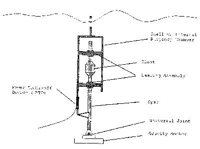
A WEC embodying the invention includes a shell and a shaft which
are designed to move relative to each other to convert the force of the waves
into
mechanical energy. In the discussion to follow, the shell is generally
depicted or
3c
CA 02537106 2006-02-22
WO 2005/069824 PCT/US2005/001100
referred to as the moving member and the shaft as the non-moving or
mechanically grounded member. But, the opposite may be the case and even
both the shaft and shell may move relative to each other. The WEC includes a
power-take-off device (PTO) coupled between the shell and the shaft to convert
the mechanical power available from the WEC into electrical energy. This is
the
desired output which is to be produced as efficiently as possible.
Applicants' invention resides, in part, in the use of apparatus and methods
for increasing the displacement and velocity (and the acceleration) of the
shell to
increase the power available from the WEC and the electric output from its
PTO.
According to one aspect of the invention, the displacement and velocity (and
acceleration) of the shell is increased by selectively supplying energy to the
shell
during portions of a wave cycle; where the energy supplied is obtained from a
source previously supplied by the PTO or from an independent source. Although
energy is expended to move the shell, the movement is such that there is a
significant net gain in the power generated by the WEC.
In a system embodying the invention a means is provided to absorb or
obtain energy from the WEC and which selectively imparts energy to the WEC
so as to increase the displacement and velocity (and the acceleration) of the
shell for increasing the net energy produced by the WEC. This is in contrast
to a
typical power capturing system, which can only absorb mechanical energy. The
energy absorbing means and the energy imparting means may be implemented
by the same device capable of operating bi-directionally (in two different
modes)
or it may be implemented using one device optimized for power absorption from
4
CA 02537106 2006-02-22
WO 2005/069824 PCT/US2005/001100
the WEC-shell and another device optimized to impart (supply) energy to the
WEC-shell.
In systems embodying the invention a PTO coupled between the shell and
shaft may be a generator (or an equivalent mechanical or hydraulic device) for
converting the energy available from the WEC into electrical energy. As noted
above, it is desirable, though not necessary, that the PTO-generator also be
able
to function as a motor (or a like mechanical or hydraulic device) which when
supplied with power can cause the desired movement between the shell and the
shaft of the WEC. Thus, in systems embodying the invention, when a single
device is used the PTO must selectively be able to function as both a power
supplying device (PSD) and a power extraction device.
Applicants' invention also includes a method to control the electrical load
of the electrical generator driven by the WEC so as to match the impedance of
the WEC load to the input so as to maximize conversion efficiency and power
output.
The invention may be implemented using a 4-quadrant power converter
which controls the flow of power to or from the PTO/PSD. By way of example,
the PTO/PSD may be a generator/motor or an equivalent mechanical or
hydraulic device. In systems making use of a generator/motor device, at
times, the generator functions as a load on the buoy (WEC) extracting energy
from it, while at other times it expends energy and functions as a motor
applying a force (and energy) to the buoy. The 4-quadrant power converter
used in systems embodying the invention may be computer controlled so as to
CA 02537106 2006-02-22
WO 2005/069824 PCT/US2005/001100
either enable current to be drawn form the system or for current to be
supplied
to the system. The computer algorithm may be used to adjust generator current
as a function of buoy speed, position and/or acceleration. The computer may
be programmed to determine when and how energy is supplied to the WEC-
shell to optimize the desired electric output.
BRIEF DESCRIPTION OF THE DRAWINGS
In the accompanying drawing like reference characters denote like
components; and
Figure 1 is a diagram identifying various relevant components of a WEC
system deployed in a body of water which may be used to practice the
invention;
Figure 1A is a simplified mathematical model of a WEC which may be
used to practice the invention;
Figures 2A-2E are diagrams showing and identifying different WEC
structures and components which may used to practice the invention;
Figure 3 is a block diagram of a prior art WEC system, showing a WEC
101 which is coupled to mechanical ground 108 via a mechanical spring 102 and
a damper 170 comprised of elements 103,104, 105,106,109 and 110;
Figure 3A is a simplified equivalent block diagram of Fig. 3;
Figures 4 through 6 illustrate various systems and methods to `tune' the
mechanical properties of a WEC for optimizing the extraction of energy from
ocean waves, in accordance with the invention;
6
CA 02537106 2006-02-22
WO 2005/069824 PCT/US2005/001100
Figures 7A, 7B and 7C illustrate key elements of AIMS systems used to
practice the invention;
Figure 8 is a block diagram of an AIMS control system used to practice the
invention;
Figure 9 is a diagram depicting the functions performed by a 4-quadrant
power converter used in practicing the invention;
Figure 10 is a diagram of a portion of the electronics of a power converter;
Figures 11 and 11A are highly simplified block diagrams of a system embodying
the invention where the power take off device (PTO) is a linear electric
generator
(LEG);
Figure 12 is a diagram of idealized waveforms associated with the
operation of a WEC, with "strong" restoring positional forces, in accordance
with
the invention and in comparison to the prior art; and
Figure 13 is a diagram of idealized waveforms associated with the
operation of a WEC, with "weak" restoring positional forces, in accordance
with
the invention and in comparison to the prior art.
DETAILED DESCRIPTION OF THE INVENTION
Figure 4 illustrates a system embodying the invention in which a WEC-
shell 5 is coupled to a power-take-off device (PTO) 170 at whose output is
produced the desired electrical energy extracted from the WEC. Fig. 4 also
shows an electrical/electronic control module 120 connected between the moving
shell 5 and mechanical ground (i.e., the shaft of the WEC). Control module 120
7
CA 02537106 2006-02-22
WO 2005/069824 PCT/US2005/001100
is used to perform the function of a spring corresponding to the mechanical
spring of the type shown in Fig. 3. However, the function(s) performed by
module 120 define significantly over the function of the spring 102 shown in
Fig.
3, in that the spring 102 is a passive device, while module 120 (as discussed
below) is an active device, programmed to control when and how energy is
supplied to the WEC-shell in order to increase the net power absorbed by the
WEC from the waves and which is made available to the PTO for producing a
desirable increased output voltage and current.
Figure 5 illustrates that the module 120 used to produce a "spring -like"
function includes an energy storage module 202 (which may be a local or an
external source of power), a control module 201 for controlling the
application of
the power from power source 202 to a motor.203 for driving a linear to rotary
translator 204. The control module 201 may include a computing device, as
shown in Figs. 7A-8 and 11,11A. As shown in those figures the control module
may be driven and controlled by command signals (not shown in Figs. 4 or 5)
for
controlling when and how the motor 203 is driven. Module 201 may also include
a 2 or 4-quadrant power converter for controlling the application of power to
the
motor.
In Figs. 4 and 5, the PTO 170 includes a linear to rotary translator
(103,104, 105) driving a generator 106 for producing an output voltage applied
via lines 109 to a load 110.
Figure 6 illustrates a system embodying the invention in which several of
the function(s) to be performed by module 120 and by PTO 170 may be
8
CA 02537106 2006-02-22
WO 2005/069824 PCT/US2005/001100
performed using the same equipment; but in this case equipment is selected
which can function bi-directionally and the equipment is operated bi-
directionally
to achieve the desired functions. Thus, in Fig. 6, module 120 and 170 are
combined into a single block which contains a motor/generator 206 and a
control
module 201 which includes a 4-quadrant power converter and a computing
device. As detailed below, for one condition of signals, power absorbed by the
shell 5 drives the linear to rotary translator 103, 104, 105 and causes
motor/generator 206 to function as a generator producing a desired electrical
output voltage and current which is coupled via the 4-quadrant power converter
in module 201 to supply an output load 110, which for ease of description is
shown as a resistor, but which could be a complex load, as shown in the other
figures.
In order to better understand the discussion to follow, it should be noted
that, as shown in several of the figures, a WEC embodying the invention
includes
a shell and a shaft which are designed to move relative to each other to
convert
the force (F1) of the waves into mechanical energy. In the discussion to
follow,
the shell is generally depicted, or referred to, as the moving member and the
shaft as the non-moving or mechanically grounded member. But, the opposite
may be the case and even both the shaft and shell may move relative to each
other. The WEC includes a PTO coupled between the shell and the shaft to
convert the mechanical power available from the WEC into electrical energy.
Thus, the WEC is used to extract, or absorb, power (energy) from the waves and
9
CA 02537106 2006-02-22
WO 2005/069824 PCT/US2005/001100
the PTO in turn extracts power (energy) from the WEC and functions as a
damper on the WEC.
Water waves acting on a wave energy conversion device (WEC) will exert
a force (F1) on the WEC-shell due to the changes in water pressure caused by
the wave. The power absorbed by the WEC (which can subsequently be used to
produce and/or generate electricity by the WEC) due to the waves is equal to
the
force (F1) of the wave times the velocity (v) of the WEC (shell) as it moves;
[P= (F1) x (v)].
It is known that in many situations where an object is responding to wave
forces, that the force (F1) of the wave applied to the object (WEC) is
independent of the motion of that object (i.e., the wave force felt by a
stationary
object is approximately equal to the wave force felt by a slowly moving
object).
Hence, if it is desired to increase the power absorbed by a particular WEC
(and
to have more power available from a WEC), this can only be done by increasing
the velocity of the WEC, (the force of the waves not being controllable). For
example, a doubling of the velocity of the WEC will lead to an instantaneous
doubling in the mechanical power absorbed by the WEC. This can then be
available from the WEC for conversion to electrical energy.
Applicants' invention resides, in part, in the use of apparatus and methods
for increasing the displacement and the velocity of the WEC-shell to increase
the
net power available from the WEC and to increase the electric output from the
WEC's PTO. According to one aspect of the invention, the displacement and the
velocity of the WEC are increased by selectively applying energy to the WEC
CA 02537106 2006-02-22
WO 2005/069824 PCT/US2005/001100
during portions of a wave cycle. This includes a computer based system to
determine when the energy should be supplied to best achieve the desired
results. It also includes the selection of appropriate system signals (e.g.,
displacement, velocity, acceleration) to determine when and how energy should
be supplied to the WEC-shell. The energy supplied to drive the WEC -shell is
obtained either from a power source previously supplied/charged by the PTO or
from an independent source. Although energy is drawn from the system to move
the WEC-shell, the movement of the WEC -shell is such that the shell will
produce more energy as a result of the movement and there is a significant net
gain in the power generated by the WEC.
As detailed below, an aspect of the invention is the ability to impart
mechanical power in a controlled manner and at controlled, selected times to
the
WEC-shell to increase its displacement and velocity at selected points of the
wave cycle. This is in contrast to a typical power capturing system, which can
only absorb mechanical energy.
The invention applies to all WECs, even where they have different
positional restoring forces. For example, a submerged WEC-shell will tend to
have "weak" positional restoring forces, while a WEC-shell floating on the
surface
of the water will tend to have "strong" positional restoring forces.
Positional restoring forces are forces which tend to cause the shell of the
WEC to return to some "rest" or "neutral" location. This force can be the
result of
hydrostatic restoring (i.e. a floating hull will return to its initial
position when
displaced) or some mechanical spring (e.g. a large coil spring fixed between
the
11
CA 02537106 2006-02-22
WO 2005/069824 PCT/US2005/001100
shell of the WEC and the WEC grounding component). "Weak and "strong"
positional restoring forces refer to the size of the restoring forces relative
to the
inertial forces required to oscillate the WEC-shell at the frequency of the
surface
waves. While the general characteristics of the AIMS apparatus and method are
the same for the cases of strong and weak positional restoring force, the
operation for the two cases differs in some respects, as discussed below. in
any
event, it is shown that by application of the invention the amount of energy
extracted from the waves is increased for both cases.
It may be assumed that the motion of the WEC-shell is sinusoidal, as is
the forcing of the wave. The relationship between the phase of the WEC-shell
and the wave force is such that when the WEC-shell reaches its maximum
displacement from its neutral position and begins to be forced towards the
zero-
displacement position, the wave force is acting in such a manner as to
accelerate
the WEC-shell towards the zero-displacement position. In "prior art" systems,
the WEC-shell is allowed to accelerate towards the zero-displacement position
and its PTO absorbs some of the mechanical energy of the WEC.
In contrast thereto, in systems embodying the invention, the displacement
and velocity of the WEC-shell are increased to produce more energy (power).
By way of example, in the case of weak positional restoring forces (see Fig.
13),
as the shell moves in one direction (e.g., up) and reaches its maximum (e.g.,
positive) displacement from neutral, its velocity goes towards zero. The point
(e.g., tA in Fig. 13) at which the displacement and velocity of the shell
becomes
zero (and first begins to increase) is sensed and power is then applied to the
12
CA 02537106 2006-02-22
WO 2005/069824 PCT/US2005/001100
shell (or the shaft) to increase its displacement, speed and acceleration.
Power is
applied to the shell via the PTO (and/or any suitable power supplying device -
PSD) which imparts energy to the WEC - shell instead of absorbing energy from
the WEC. Depending on the design of the system and the system requirements,
power may be applied for a longer or shorter time interval. This procedure is
repeated when the shell moves in the opposite direction (e.g., down) and
reaches its maximum (e.g., negative) displacement (e.g., t=6 in Fig. 13). That
is,
the system senses the velocity of the shell as it decreases and goes to zero,
and
also senses the point (and time) at which the shell has reached maximum
displacement and just starts to accelerate in the opposite direction. The AIMS
system then gives the WEC a boost by supplying energy (power) to the shell via
the PTO (and/or any suitable power supplying device -PSD). This procedure
has the effect of increasing the displacement of the WEC-shell (compared to
the
prior art) and substantially increasing the velocity (and acceleration) of the
WEC-
shell. As the WEC-shell velocity and acceleration increase,, the mechanical
wave power absorbed by the WEC-shell (and the energy subsequently imparted
by the WEC-shell to its PTO) increases dramatically. The dramatic increase in
power absorbed by the WEC may then be made available to the PTO which can
absorb the increased power and convert it to produce an increased electrical
energy output. It should be appreciated that the power infusion is intended to
cause the WEC to resonate and/or oscillate, resulting in a more efficient
operation.
13
CA 02537106 2006-02-22
WO 2005/069824 PCT/US2005/001100
Thus, once the WEC-shell has reached a certain position, velocity, and/or
acceleration, the PTO is used to absorb the mechanical energy from the WEC
and to convert it into electrical energy. In AIMS systems and method embodying
the invention, the PTO absorbs energy for a shorter amount of time than in
prior
art systems, but, there is much more energy to absorb.
The AIMS apparatus and method also improves power conversion
efficiency when the WEC has strong positional restoring forces. An AIMS-
controlled PTO improves on the prior art method by imparting energy to the WEC
during portions of each wave cycle, thus increasing the maximum displacement,
and hence velocity of the WEC, which makes for increased wave power
absorption by the WEC-shell. For the case of the WEC exhibiting strong
positional restoring forces, its PTO imparts energy to the WEC-shell as the
shell
approaches its maximum displacement. For example, as shown in Fig. 12, the
shell reaches its maximum displacement at time tB, but power is applied to the
WEC-shell before that time. This has the effect of delaying the instant
(extending
the time) at which the WEC-shell reaches its maximum displacement. Because
the WEC reaches its maximum displacement later in the wave cycle, the WEC
reaches its peak velocity later. For this case, the AIMS apparatus and method,
by controlling the timing when power is supplied tothe WEC-shell, causes the
peak of WEC-shell velocity to approximately coincide with the peak wave force.
Because mechanical wave power absorbed by the WEC-shell is the product of
the wave force and the WEC velocity, this leads to an increase in mechanical
power absorption by the WEC, which leads to an increase in maximal WEC
14
CA 02537106 2006-02-22
WO 2005/069824 PCT/US2005/001100
displacement. This increase in maximal WEC displacement in turn leads to
increased WEC velocity, which leads to increased power absorption.
Eventually, the absorbed power stops increasing with increased WEC velocity
and stroke, due to damping effects, and the inability of the wave field to
exert
force on a quickly moving object. Thus, in systems embodying the invention,
for
the cases of "weak" and "strong" positional restoring forces, the maximum
displacement and velocity (as well as the acceleration) of the WEC shell are
increased leading to increased power absorption by the WEC.
To further explain the invention, reference is made to the waveforms
shown in Figs. 12 ("strong" restoring forces) and 13 ("weak" restoring
forces).
Assume that waveform A represents the force of the ocean waves applied to a
WEC of the type shown in the figures (e.g., Fig. 11). Waveform B depicts the
displacement of the WEC in response to the application of the AIMS invention
to
the system. Waveform C depicts the displacement of the WEC in accordance
with the prior art. Note that in accordance with the invention, the
displacement
shown in Waveform B is significantly greater than the displacement seen in
Waveform C. In systems embodying the invention , the larger displacements (at
the two ends of the excursion of the WEC-shell) are obtained by imparting
energy to the WEC at, or near, the top end and the bottom end of the travel of
the WEC-shell, when the velocity of the shell is going towards zero, just
reaches
zero and/or passes zero). Concurrent with the greater displacement is a
significant increase in the velocity of the WEC-shell as it goes from one end
of its
travel to the other end of its travel. There is also a benefit due to the
favorable
CA 02537106 2006-02-22
WO 2005/069824 PCT/US2005/001100
shift in phase resulting in a still greater gain in power. (As above, it is
assumed
that the shaft is fixed while the shell moves up and down relative to the
shaft.
This is done for ease of description only. In the description and in the
appended
claims, it should be understood that the shell may be fixed while the shaft
moves
relative to the shell and/or that the shaft and shell may both move relative
to each
other.)
The top portion of Fig. 12 (waveform A) represents the force of the wave
on the WEC. The second portion of Fig. 12 (waveforms B and C) represents the
displacement of the WEC from the "rest" position. The third portion of Fig. 12
(waveforms D and E) represents the force (FPTO) of the power take-off device
(PTO). The fourth portion of Fig. 12 (waveforms F, H, G, I) represents the
instantaneous power and average power absorbed by the PTO. Waveforms F
and G represent instantaneous power and waveforms H and I the average
power. The net gain in power using the invention may be seen by comparing
waveforms H and I, where H is clearly more positive than I.
The waveforms of Figs. 12 and 13 demonstrate the benefits of the
proposed AIMS apparatus and method when compared to the prior art. The
graph of instantaneous power (waveform F) absorbed by the PTO indicates that
the absorbed power is at times negative. Negative absorbed power implies
positive imparted power, which means that the PTO is acting as a (PSD) motor
(i.e., is using previously generated or external power to drive the WEC).
Referring to Fig. 12, the operation may be briefly described as follows:
Starting
at t = 0 seconds, the WEC has reached its largest negative displacement from
its
16
CA 02537106 2006-02-22
WO 2005/069824 PCT/US2005/001100
rest position. At this time, the PTO begins to impart energy (i.e. the PTO
acts to
accelerate the WEC) to it, thus driving it upwards. In the example, at
approximately 1.5 seconds, the WEC passes through its rest point, and PTO
begins to draw energy from the WEC (i.e. the PTO acts to decelerate the WEC.)
Note that at this point, the velocity of the WEC is large relative to the non-
AIMS
case. The PTO continues to draw energy from the WEC until the WEC reaches
its maximum extent at approximately 3 seconds. In this embodiment of the
AIMS method, the net power absorbed by the PTO is shown by the horizontal
dashed line in the figure. Note that the range over which the PTO draws power
from the WEC-shell may be controlled and/or varied.
This method of imparting energy to the buoy just after it has reached its
maximum extent has the effect of sending it slightly past its next "natural"
turning
point, thus changing the phase relationship between wave force and WEC
motion. When properly implemented and executed, this change in phase
relationship provides a benefit for power conversion by aligning the wave
force
with the velocity of the WEC. Note, that in figure 12, the maxima in the
magnitude of the wave force occur at 1.5 seconds, 4.5 seconds, 7.5 seconds
etc.
This coincides with the velocity maximum of the WEC system with the AIMS
apparatus, but not for the WEC system without the AIMS apparatus. Clearly, in
accordance with the invention, the displacement of the shell in the up
direction
will be greater than it would be in the standard, prior art, scheme; and,
likewise,
the displacement of the shell in the downward direction extends significantly
below the bottom for the standard (non-AIMS case). By way of example, in Fig.
17
CA 02537106 2006-02-22
WO 2005/069824 PCT/US2005/001100
12, the shell subjected to the AIMS process is displaced approximately 5 units
during the time the shell (without AIMS) is displaced 2 units, which for this
case
indicates that the velocity of the shell has more than doubled.
As explained above, the efficiency of a WEC can be significantly
increased by selectively adjusting the system spring (a) and load damping
(,QIoad)
characteristics to match the wave conditions. Apparatus to perform this tuning
is
illustrated in Figures 7A, 7B, 7C, 8, 1land 11A. The system spring constant
corresponds to displacement of the WEC (e.g., shell) and the load damping
constant corresponds to the power taken by the PTO from the WEC (and
converted to useful electric energy). In accordance with the invention, the
system
spring constant may be adjusted by selectively supplying power to the WEC.
In the basic Active Impedance Matching System (AIMS), the output
current of the PTO (assumed to be a generator for ease of description) is
controlled such that the shell (assumed, for purpose of example, to be the
moving member) is put in resonance with the waves. Assuming the PTO to
normally function as a generator, the AIMS system requires that the generator
also act as a motor for portions of each wave cycle and as a generator for
other
portions of each wave cycle. Useful or output electrical energy is generated
during most of the wave cycle (when the PTO functions as a generator) and is
stored. Some stored (or external) energy is returned to the system during the
"motoring" portions of the wave cycle. The AIMS system includes a four-
quadrant
power converter, capacitors, various sensors, and computer-based control
algorithms as shown in the figures
18
CA 02537106 2006-02-22
WO 2005/069824 PCT/US2005/001100
In Figs. 7A, 7B and 7C there is shown an embedded processor or control
computer 700 which continuously samples various sensors, including WEC-shell,
position and speed and/or acceleration. An algorithm residing in this control
computer 700 determines generator current set-point commands that are
continuously sent to a four-quadrant power converter, 702. This converter 702
can either load the generator or drive the generator so it functions like a
motor
(i.e. apply positive or negative current load as determined by the control
computer).
A "four-quadrant converter" allows positive or negative torque (or force) to
be applied to a motor/generator while the motor/generator is either
accelerating
or decelerating. Thus, it is possible with a four-quadrant converter to have
the
following four conditions: 1) positive torque (torque for a rotary electric
generator
or force for a linear electric generator) with positive speed, 2) positive
torque
(force) with negative speed, 3) negative torque (force) with positive speed,
and 4)
negative torque (force) with negative speed.
In the case of a system with a linear electric motor/generator (e.g., a
LEG), force is the controlled parameter, and is approximately proportional to
the
generator current. In the case of a system with a rotary motor/generator,
torque
is the controlled parameter which is approximately proportional to generator
current. The term "motor/generator" is used here because the electromechanical
machine can function in either mode, depending on the polarity of the torque
(force) and the speed.
19
CA 02537106 2006-02-22
WO 2005/069824 PCT/US2005/001100
In Fig. 7A, a power take off device (PTO) 706A is shown connected
between a shell 5 of the WEC and its column or shaft 3, which is assumed to be
mechanically grounded. The PTO 706A may be any type of electric generator/
motor or any type of mechanical or hydraulic device such as, for example, a
rack
and pinion geared arrangement, a ball and screw arrangement, a hydraulic
cylinder, a hydraulic motor, and/or any apparatus which can convert the
mechanical motion between the shell and the shaft into electrical energy.
The PTO is shown connected to a rotary electric generator/motor 704A
which is connected to a 4 quadrant power converter 702. In Fig. 7A there is
shown a computer or embedded microprocessor 700 to which is applied: (a) data
pertaining to the position of the shell relative to the shaft; and (b) data
pertaining
to the speed of the shell relative to the shaft. Acceleration data may also be
supplied or be determined by the computer. The computer 700 is programmed
to produce desired current signals 701 which are applied to the power
converter
702, in response to predetermined or programmed condition of speed,
displacement and other criteria (e.g., acceleration) set into the computer.
The primary aim of the system is to have the PTO 706A and the generator
704A convert the wave energy absorbed by the WEC-shell into
electromechanical energy and to produce, as efficiently as possible, an output
voltage and current at the output 720 of the power converter 702. The output
720 of the power converter 702 may be applied to a simple or complex load. The
load may include: a) a DC/DC converter 721 coupled to a capacitor bank 722 (or
battery) where the electrical energy is stored; and/or b) a DC load 723 and a
DC
CA 02537106 2006-02-22
WO 2005/069824 PCT/US2005/001100
source 724; and/or c) an inverter 725 to generate an AC power signal (whose
frequency and amplitude is controlled) which can be applied to an AC load 726
or
an AC source 727.
In systems embodying the invention, during certain portions of the ocean
wave cycle, under the control of computer 700, power from the system is
supplied via the converter 702 to the generator/motor 704A which then drives
the
PTO 706A such that energy (power) is supplied to the shell to cause it to move
in
a direction which will produce an over all power gain. That is, by using
energy
from the system to drive the shell and by controlling the time and manner in
which the energy is supplied to the WEC-shell, more useful energy is obtained
from the waves and the system than in the prior art.
The position data signal shown in Figure 7A may be a current command
component which is a function of the displacement of the WEC shell. This
component represents a "spring" characteristic. A large displacement of the
WEC shell from a null position results in a large current and a resultant
generator
force to return the WEC shell to the null point. The speed data signal is
another
current command component which represents a "resistive" or damping
characteristic- A high WEC shell speed results in a high generator voltage.
The
generator current, as determined by the control algorithm and four-quadrant
power converter is high in this case. Thus, the programmed generator current
consists of a real and reactive component.
As shown in Figure 7A, an AC power generated by the PTO 706A and the
rotary electric generator 704A may be converted to DC by the four-quadrant
21
CA 02537106 2006-02-22
WO 2005/069824 PCT/US2005/001100
pulse-width-modulated converter 702 The DC output current of this four-
quadrant
converter is primarily DC with a variable component that follows the power of
the
generator. The DC component is proportional to the average power out of the
four-quadrant converter. To keep the power to the load positive and steady,
power from the generator controller is fed to a DC bus supported by one or
more
banks of capacitors (or some other energy storage device). The capacitors
store
energy when the generator output exceeds the inverter demand and release
energy when the generator output is below the inverter demand. The inverter
demand is slowly changed to maintain energy balance of the capacitors.
This system requires some energy to be fed back into the wave energy
converter during a portion of each wave cycle. As described above, this energy
can be that which has been stored in capacitors. For applications where wave
energy power is fed into a utility power grid, the energy to be fed back into
the
wave energy converter can be supplied by the utility power grid. The net
average
power to the utility power grid will be positive.
Figure 7B is generally similar to Fig. 7A, except for the power take off
device which is shown to include a permanent magnet assembly (PMA) 706B
and an induction coils assembly (ICA) 704B to form a linear electric generator
(LEG). In fig. 7B, the coil assembly is shown to be mechanically grounded.
This
suggests that the PMA is connected to the moving shell 5, causing voltage and
current to be produced across the coils of the ICA. The voltage and current
generated by the coils is supplied to the 4-quadrant pulse width modulated
power
converter 702. As in Fig. 7A, the operation of the power converter 702 is
22
CA 02537106 2006-02-22
WO 2005/069824 PCT/US2005/001100
controlled by computing device 700 which controls power extraction and the
supplying of power in response to position and speed (and acceleration) data
generated by movement of the shell relative to the shaft. Under the control of
the
computer, the converter 702 in turn determines when and how power is taken
from the WEC-shell and when power is supplied to the WEC-shell. In Fig, 7B,
power would be supplied to the coils or drawn from across the coils. The
operation of the system is otherwise similar to that of Fig. 7A and need not
be
further detailed.
Fig. 7C is generally similar to Fig. 7B, except that in this configuration of
the WEC both the shaft 101 a and the shell 101 b can move relative to each
other.
Key elements of the AIMS system embodying the invention include the
following:
1. WAVE ENERGY ABSORBER- This component (which may be formed by
the combination of the shell and the shaft of the WEC) absorbs mechanical
energy from ocean waves and applies a force to a power take-off device
(PTO).
2. POWER TAKE-OFF DEVICE (PTO)- This component, typically connected
between the shaft and the shell of the WEC, converts the linear force and
motion of the wave energy absorber and converts it to an intermediate or
final usable form of force and motion. For example, this component could be
a hydraulic cylinder that converts linear force and motion to hydraulic fluid
pressure and flow. This component could also be a device that translates
linear force and motion to rotary torque and angular displacement. This
23
CA 02537106 2006-02-22
WO 2005/069824 PCT/US2005/001100
component may also be a linear electric generator (LEG) attached to the
shell and shaft and which can convert their relative motion to an AC voltage
and current.
3. MECHANICAL-TO-ELECTRIC CONVERTER- This component converts
mechanical linear force (or torque) and linear displacement (or angular
displacement) to electric current and voltage, and vice versa. As an
example, this component could be a permanent magnet generator that can
also act as a motor.
4. MECHANICAL GROU ND- refers to one part of the PTO (shell or shaft) held
relatively stationary so that the PTO can be subjected to a force applied by
the WAVE ENERGY ABSORBER. This component could be a long spar
(shaft) anchored to the ocean floor.
5. FOUR-QUADRANT POWER CONVERTER- A "four-quadrant converter" is
an electronic device that allows positive or negative torque (or force) to be
applied to a motor or generator while the motor or generator is either
accelerating or decelerating. Thus, it is possible with a four-quadrant
converter to have the following four conditions: 1) positive torque (force)
with positive speed, 2) positive torque (force) with negative speed, 3)
negative torque (force) with positive speed, and 4) negative torque (force)
with negative speed. In the case of a system with a linear motor/generator,
force is the controlled parameter, and is approximately proportional to the
generator current. In the case of a system with a rotary motor/generator,
torque is the controlled parameter which is approximately proportional to
24
CA 02537106 2006-02-22
WO 2005/069824 PCT/US2005/001100
generator current. The term "motor/generator" is used here because the
electromechanical machine can function in either mode, depending on the
polarity of the torque (force) and the speed. The four-quadrant converter is
generally a pulse-width-modulated (PWM) device comprised of a number of
solid-state switches and energy storage components. The duty-cycle of the
solid-state switches is controlled in a manner to regulate the current flow
into and out of the motor/generator.
6. CAPACITOR BANK (722)- functions to store electric energy during the
generator portion of the wave cycle and to release electric energy during the
motor portion of the wave cycle. The capacitor bank can either be
connected directly to the DC bus connected to the FOUR-QUADRANT
CONVERTER or fed to the DC bus via a bidirectional power converter.
7. BIDIRECTIONAL DC/DC CONVERTER- regulates the flow of electric
energy into and out of the CAPACITOR BANK. The flow of energy can be
controlled so as to maintain a steady DC bus voltage or maintain the state
of charge of the capacitor bank.
8. INVERTER (725)- may be a pulse-width-modulated device that converts
DC power to highly regulated AC power. If desired, this device can be
bidirectional so that AC power can be converted to DC power that can feed
the four-quadrant converter and back-drive the electric generator (i.e. the
mechanical-to-electric converter).
9. DC LOAD (723)- is the end user of the power generated by the wave
energy converter in certain applications.
CA 02537106 2006-02-22
WO 2005/069824 PCT/US2005/001100
10. DC SOURCE (724)- may be a source of power that is fed back to the
generator via the electric generator. This component would generally not be
required for systems connected to and supplying power to a utility power
grid.
11. AC LOAD (726)- is the end user or users of the power generated by the
wave energy converter in certain applications.
12.AC SOURCE (727)- is the source of AC power in an AC power system
application.
13. DISPLACEMENT (731) AND/OR VELOCITY (733) SENSORS
Displacement sensors (e.g., 731 in Fig. 7A) sense the displacement of the
wave energy absorber in relation to the mechanical ground or, in the case of
a dual absorber system, senses the relative displacement of the two wave
energy absorbing elements. A separate velocity sensor (e.g., 733 in Fig. 7A)
can sense the relative velocity of the wave energy absorber in relation to the
mechanical ground or, in the case of a dual absorber system, senses the
relative velocity of the two wave energy absorbing elements.
14. EMBEDDED PROCESSOR OR COMPUTER (e.g., 201, 700 and 81)- is a
computational device that receives data inputs from various sensors,
receives parameter and/or operating mode inputs from a system operator,
and transmits outputs to the four-quadrant converter. The output includes a
signal that adjusts the four-quadrant converter AC current set point. The
computation device (e.g., 700 in Fig. 7A) may be programmed and used to
26
CA 02537106 2006-02-22
WO 2005/069824 PCT/US2005/001100
control when and how power is extracted from the WEC and when power is
supplied to the WEC.
15. PROCESSOR FOR CONTROL ALGORITHMS-
This component (which may be part of the computer) receives data that
indicates the relative displacement of the wave energy absorber and mechanical
ground, or in the case of a dual-absorber system, receives data that indicates
the
relative displacement between the two wave energy absorbing elements. The
algorithm can compute the time derivative of this relative displacement to
determine the relative velocity between the wave energy absorber and
mechanical ground or between two wave energy absorbing elements.
Alternatively, the velocity can be supplied to the control algorithm by a
velocity
sensor. In addition, the algorithm can calculate the time derivative of
velocity to
determine the acceleration of the shell or shaft.
This component may be used to determine a desired value for
motor/generator current (IGENSET) as a function of wave energy absorber(s)
displacement and velocity. This current is a function of the displacement (x)
of
the wave energy absorber from a neutral position (xo). As the wave energy
absorber displacement from the neutral position (x-xo) increases, so does the
"spring" component of the desired motor/generator current (IGENSET). The
desired
value of motor/generator current is also a function of wave energy absorber
velocity. As the wave energy absorber velocity increases, so does the
"damping"
component of the desired motor/generator current. The desired motor/generator
current is the algebraic sum of the spring and damping component:
27
CA 02537106 2006-02-22
WO 2005/069824 PCT/US2005/001100
IGENSET = a (X-XO) + R X' +AX
Where: a is the spring constant that relates desired generator current to wave
energy absorber linear displacement relative to a desired neutral point (x-
xo), 3 is
the damping constant that relates desired motor/generator current to wave
energy absorber speed (x'), is the mass constant that relates desired
motor/generator current to wave absorber acceleration (x"), x is the linear
displacement of the wave energy absorber, xo is the desired wave energy
absorber neutral (or null) point, x' is the time derivative of the linear
displacement (i.e. velocity) and x" is the time derivative of the linear
velocity. This
desired value for motor/generator current is converted to an electric signal
that
can be received by the four-quadrant converter.
Referring to Fig. 8 (and Fig. 11), there is shown a wave energy absorber
(WEC shell) 5. A force Fwave is applied to the shell 5 causing it to move. The
position or displacement (x) of the shell 5 may be sensed or measured (e.g.,
via
sensors 731) as the shell moves relative to the shaft 3 (not shown). The
displacement may be expressed as a function of a n ull position xo, with the
shell
moving up and down relative to the null position. The velocity (v) of the
shell may
be calculated (module 810) by determining dx/dt or by using a speed sensor.
The
acceleration ("a") of the shell may be calculated (module 810a) by determining
dv/dt or by using an acceleration sensor. The shell displacement, the
velocity,
and acceleration are supplied to an embedded controller or computer 81 (which
may be equivalent to computer 700 of Fig. 7A). The computer 81 is shown to
include data processing section 810 for calculating the shell velocity (if an
28
CA 02537106 2006-02-22
WO 2005/069824 PCT/US2005/001100
independent sensor for performing this function is not used). The computer 81
is
also shown to include a processing section 811 for determining the offset of
the
shell relative to the null position (xo) to produce a signal referred to as
the shell
position error (x- xo ). The computer 81 is also shown to include a data base
and
processor section 812 into which various parameters such as the mass and
volume and the displacement of the WEC can be supplied (and stored) to
generate: (a) a term representing the spring constant (k) of the WEC; and (b)
a
term representing the damping constant (b) of the WEC. Note that the spring
constant (k) represents and is a function of the forces tending to return the
shell
to its null position and is position dependent. Note also that the damping
constant (b) represents and is a function of power taken out of the system and
system losses and is speed dependent. The computer 812 is also shown to
include a processor section 813 to which the following signals are supplied:
(a)
spring constant (a), (b) damping constant (R); (c) mass constant ( ), (d) the
shell
velocity (v), (e) shell neutral position (xo) and (f) the shell position error
signal (x-
xo).
The processor 813 is programmed to calculate the force, referred to as
FPTO, The application of this force may require that power be supplied to the
WEC. However the net effect of its application is that it tends to optimize
the
response of the WEC and to increase the net power produced by the WEC and
hence its efficiency. The processor determines FsPRING, FDAMPER and FMASS
which when summed equal FPTO which, as shown in Fig. 8 may also be
expressed as:
29
CA 02537106 2006-02-22
WO 2005/069824 PCT/US2005/001100
FPTO= FSPRING + FDAMPER + FMASS = a (X- XO) +(3 X' + p. x". Eq. A
The processor 813 is also programmed to supply digital data to a digital to
analog interface circuit 814 to produce a generator current set point signal
referred to as IGENSET which is a function of FPTO. The digital signal IGENSET
is
applied to an input of a 4-quadrant power converter 90 (which may be like
converter 702 of Fig. 7A). The 4-quadrant power converter 90 is shown
connected between block 90 and block 110. Block 100 may include the load
driven by the WEC and/or a power supply charged by the WEC and or a supply
for storing energy which may be used to provide a current to the PTO 114.
Figure 8 shows a generator current IGEN produced by the power converter 90
which is applied to a generator 112 (which when driven functions like a motor)
so
a to apply a force or a torque to a power take off device 114 to produce a
desired
PTO force (FPTO), which is shown to be summed (symbolically in summer 120) to
produce the net force applied to the shell 5. It should be appreciated that
the
power converter controls the current of the generator to produce the desired
PTO
force (FPTO).
Characteristics of FPTO used in practicing the invention.
FPTO is positive if ax + Rx' + x" >0
FPTO is negative if ax + 13x' + x" <0
Ignoring the and x" part, it can be seen that the PTO force can be positive
when the WEC is above or below the neutral point. It all depends on the sum of
the a x and R x' computations. For example, there are two cases when the WEC
is above the neutral point. In one case, the speed is in a direction which
results in
CA 02537106 2006-02-22
WO 2005/069824 PCT/US2005/001100
a force that supports the spring force. In the other case the speed is in a
direction
which results in a force that opposes the spring force. Therefore, it is
necessary
to compute ax+[3x'.
In calculating the optimizing algorithm, the calculations may include the
steps
of determining the frequency (f) of the waves impacting the WEC, where w=
21T(f); determining the mass (M) of the WEC; determining the hydrostatic
restoring factor (k); determining the spring force of the WEC (b-damping); and
defining C(= [M (w2 )] - k; defining 13= b-damping; (c) determining the
position X;
determining the velocity v (where v =dxldt) and calculating the desired force
F(pto) = ax + (3 v; and applying F to WEC.
Figure 9 illustrates the functions performed by the 4-quadrant power
converter 90 (702 in Fig. 7A). The function of the power converter 90 is
conceptually similar for (a) the case of a rotary motor/generator used in
conjunction with, or as, the power take off device, or (b) the case of linear
motor/generator used in conjunction with, or as, the power take off device.
However, in the case of the rotary motor/generator due to the rotation of the
motor/generator the torque-speed graph is in terms of angular velocity (shown
along the Y-axis) and torque (shown along the abscissa) and the 4 quadrants
may be described as follows: (a) negative torque, positive speed; (b) positive
torque, positive speed; (c) positive torque, negative speed; and (d) negative
torque, negative speed. For the case of the linear motor/generator the force
speed diagram shows the Linear Velocity along the Y axis and the Force along
the X-axis and the 4 quadrants may be described as follows: (a) negative
force,
31
CA 02537106 2006-02-22
WO 2005/069824 PCT/US2005/001100
positive speed; (b) positive force, positive speed; (c) positive force,
negative
speed; and (d) negative force, negative speed.
Figure 10 is a schematic diagram of part of the 4-quadrant converter
illustrating that output currents produced by the generator are sensed and the
sensed signals are supplied to a computing device (700, 81). The computing
device supplies turn-on and turn-off signals to the switches T1-T6, shown in
the
figure. Figure 10 shows one embodiment of a four-quadrant power converter
used to control the current and torque of a three-phase brushless DC rotary
motor/generator or the current and force of a three-phase brushless DC linear
electric motor/generator. In this example, a signal that reflects the desired
generator current (or force or torque) is sent from the system controller
(computer) to the four-quadrant converter. This set-point has been computed by
the system controller and is a function of shell-spar position, speed and/or
acceleration. Generator position signals are sent from a sensor (typically an
encoder or resolver) to the four-quadrant converter. The four-quadrant
converter
has an embedded processor that receives these two sets of signals along with
actual generator current and controls the six power switches (transistors in
this
example) to turn on and off at the appropriate time to achieve the desired
current.
As the set-point is continually updated and the actual motor/generator
position is
continually changing, the four-quadrant converter power switches are toggled
on
and off to achieve the desired motor//generator current.
Figure 11 shows a LEG connected between the shaft and shell of a WEC.
In this figure the PMA is connected/attached to the shaft and the induction
coil
32
CA 02537106 2006-02-22
WO 2005/069824 PCT/US2005/001100
assembly (ICA) is attached to the shell. In a typical application, as the
shaft
moves relative to the shell (or vice versa), voltages and currents generated
across the coils of the ICA, in response to the relative motion, are fed via
switches S1 and S2 to the load. Switches S1 and S2 may be controlled by
computer 81. For ease of illustration assume that the load is a capacitor used
to
store the energy generated in the coils.
In Fig. 11, a power source (724, 727) is shown which is connected across
the coils via switches S3 and S4. The turn on and turn off of these switches
is
controlled by controller computer 81. Note that there is a variable load (VL)
coupled via switch S5 across the load. Switch S5 may also be controlled by
computer 81. Power source 724,727, may be an independent power source or
may be part of a power supply associated with the load which is charged up by
the energy obtained from the coils of the ICA.
By controlling the switches S3 and S4 and the nature of the power supply
724, 727, currents and voltages can be applied across the coils to selectively
feed back power to the shell/shaft and accomplish a degree of active impedance
matching.
Controlling the switching of S1, S2, S3 and S4 allows: (a) energy to be
extracted from the shell/shaft and to be supplied to the load; or (b) for
energy to
be supplied to the shell/shaft. The switches may be controlled in response to
position, speed or acceleration signals applied to or developed by the
computer.
The computer may be used to control the opening and closing of the switches
and the power from the supply such that positive or negative torque (or force)
33
CA 02537106 2006-02-22
WO 2005/069824 PCT/US2005/001100
may be applied to the LEG (functioning as a motor or generator) and hence to
the shaft and shell while the (motor or generator) shaft or shell is either
accelerating or decelerating. Thus, it is possible to have the following four
conditions: 1) positive torque (force) with positive speed, 2) positive torque
(force) with negative speed, 3) negative torque (force) with positive speed,
and 4)
negative torque (force) with negative speed.
Figure 11A also shows a LEG connected between the shaft and shell of a
WEC. Fig. 11A shows that the output of the ICA is coupled to a 4-quadrant
power converter (90, 702) whose output is connected the load (723, 721, 722)
to
supply the load when an electrical output is being extracted from the coil
assembly. In response to position, speed, or acceleration signals, the
computer
81 may generate signals applied to power converter 90 which enables the
converter to then supply energy to the ICA to cause the shell to move relative
to
the shaft (or vice-versa).
It should be appreciated that Applicants' invention includes apparatus and
methods for controlling the backforce of the PTO (FPTO) in a way that
increases
the power generated by a WEC. The PTO may either be a linear electric
generator (LEG) or a combination of a linear-rotary translator (e.g. rack and
pinion) and a rotary generator. The FPTO of the PTO is controlled such that
the
FPTO is a function of shell position (relative to spar) and speed or shell
position
and shell acceleration. The position, speed and acceleration dependent
backforces are controlled in a way to achieve "quasi-resonance" of the buoy
(i.e.
the PTO force combined with the WEC's natural mass and spring like behavior
34
CA 02537106 2006-02-22
WO 2005/069824 PCT/US2005/001100
make the WEC system behave like a mass-spring-damper system in resonance
with the predominant period of wave excitation incident on the WEC).
The FPTO which can be positive or negative may be expressed as:
F 0 =a=x+f =z+,u-.z
Where xis the shell-spar position relative to a desired "neutral" point x is
the
shell-spar speed x is shell-spar, a is a spring coefficient/3 is a damping
coefficient
and,u is a mass coefficient
The parameters a, P, and are chosen for the existing wave conditions in
a way that optimizes capture of wave energy by the WEC. These parameters
may be chosen by an operator and downloaded to a WEC control computer, or
they may be determined by a WEC on-board computer using various alternative
algorithms. A simple parameter selection approach is to determine the period
of
the predominant waves and select the parameters to achieve resonance for this
wave period.
The PTO force exerted between the shell and spar may be obtained by
one of the following:
1. a combination of a linear electric generator, a four-quadrant power
converter that controls current to/from the generator, and a controller that
continuously issues current (or force) set-point commands to the four-
quadrant power converter with the desired goal of driving the PTO (i.e.,
the LEG in this case) to exert a force between the shell and spar that is a
function of shell-spar position and speed, or shell-spar acceleration and
speed.
CA 02537106 2006-02-22
WO 2005/069824 PCT/US2005/001100
2. a combination of a device that translates linear force and linear motion to
rotary torque and rotary motion (e.g., rack and pinion; hydraulic ram with
hydraulic motor), a rotary electric generator, a four-quadrant power
converter that controls current to/from the generator, and a controller that
continuously issues current (or torque) set-point commands to the four-
quadrant power converter with the desired goal of driving the PTO to exert
a force between the shell and spar that is a function of shell-spar position
and speed, or shell-spar acceleration and speed.
The four-quadrant power converter can drive the linear (or rotary) electric
generator to 1) exert positive force (or torque) when the generator speed is
positive, 2) exert positive force (or torque) when the generator speed is
negative,
3) exert negative force (or torque) when the generator speed is positive, and
4)
exert negative force (or torque) when the generator speed is negative.
The four-quadrant power converter supplies power to and extracts power
from a DC power bus to enable the generator and PTO to perform the desired
force function. The DC bus may supply power to a DC load and/or an AC load via
a DC/AC converter (inverter). The DC power may also be supplied to an energy
storage device such as an electro-chemical battery or capacitor bank, either
directly or via a DC/DC converter. The DC power bus may receive power from an
electro-chemical battery or capacitor bank, either directly or via a DC/DC
converter. The DC bus and four-quadrant converter may also receive power from
an AC source via an AC/DC converter.
36