Sélection de la langue

Search

Sommaire du brevet 2537172 

Énoncé de désistement de responsabilité concernant l'information provenant de tiers

Une partie des informations de ce site Web a été fournie par des sources externes. Le gouvernement du Canada n'assume aucune responsabilité concernant la précision, l'actualité ou la fiabilité des informations fournies par les sources externes. Les utilisateurs qui désirent employer cette information devraient consulter directement la source des informations. Le contenu fourni par les sources externes n'est pas assujetti aux exigences sur les langues officielles, la protection des renseignements personnels et l'accessibilité.

Disponibilité de l'Abrégé et des Revendications

L'apparition de différences dans le texte et l'image des Revendications et de l'Abrégé dépend du moment auquel le document est publié. Les textes des Revendications et de l'Abrégé sont affichés :

  • lorsque la demande peut être examinée par le public;
  • lorsque le brevet est émis (délivrance).
(12) Brevet: (11) CA 2537172
(54) Titre français: OUTIL D'EXTRACTION DE TIGES DE CONNEXION ACTIONNE PAR LIQUIDE
(54) Titre anglais: FLUID ACTIVATED CONNECTING PIN REMOVAL TOOL
Statut: Accordé et délivré
Données bibliographiques
(51) Classification internationale des brevets (CIB):
  • B23P 19/027 (2006.01)
  • B25C 11/00 (2006.01)
  • B62D 55/32 (2006.01)
(72) Inventeurs :
  • DANIELS, MICHAEL K. (Canada)
  • GEHRLING, HERB R. (Canada)
(73) Titulaires :
  • HEAVY EQUIPMENT REPAIR LTD.
(71) Demandeurs :
  • HEAVY EQUIPMENT REPAIR LTD. (Canada)
(74) Agent: NATHAN V. WOODRUFFWOODRUFF, NATHAN V.
(74) Co-agent:
(45) Délivré: 2011-04-26
(22) Date de dépôt: 2006-02-21
(41) Mise à la disponibilité du public: 2007-08-21
Requête d'examen: 2008-02-07
Licence disponible: S.O.
Cédé au domaine public: S.O.
(25) Langue des documents déposés: Anglais

Traité de coopération en matière de brevets (PCT): Non

(30) Données de priorité de la demande: S.O.

Abrégés

Abrégé français

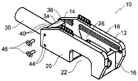
Un outil d'extraction de tiges de connexion actionné par liquide comprend un corps définissant une première cavité adaptée à recevoir une partie d'une pièce à travailler et une deuxième cavité positionnée essentiellement à la perpendiculaire et croisant la première cavité. Si un cylindre actionné par liquide est monté sur le corps dans une première orientation par rapport à la deuxième cavité, l'expansion du cylindre actionné par liquide résulte en un piston se prolongeant depuis le cylindre dans la première cavité dans laquelle la pièce à travailler est positionnée afin d'exercer une force sur une tige de connexion connectant les parties de la pièce à travailler. Si le cylindre actionné par liquide est monté sur le corps dans une deuxième orientation par rapport à la deuxième cavité, la deuxième cavité sert de compartiment d'entreposage pour le cylindre actionné par liquide.


Abrégé anglais

A fluid activated connecting pin removal tool, includes a body defining a first cavity adapted to receive a portion of a work piece and a second cavity positioned substantially perpendicular to and intersecting the first cavity. When a fluid activated cylinder is mounted to the body in a first orientation relative to the second cavity, expansion of the fluid activated cylinder results in a piston extending from the cylinder into the first cavity in which the work piece is positioned to exert a force upon a connecting pin connecting portions of the work piece. When the fluid activated cylinder is mounted to the body in a second orientation relative to the second cavity, the secondary cavity serves as a storage compartment for the fluid activated cylinder.

Revendications

Note : Les revendications sont présentées dans la langue officielle dans laquelle elles ont été soumises.


4
What is Claimed is:
1. A fluid activated connecting pin removal tool, comprising:
a body defining a first cavity adapted to receive a portion of a work piece
and a
second cavity positioned substantially perpendicular to and intersecting the
first cavity;
means for mounting a fluid activated cylinder to the body in a first
orientation
relative to the second cavity, such that upon expansion of the fluid activated
cylinder a
piston extends from the cylinder into the first cavity in which the work piece
is positioned to
exert a force upon a connecting pin connecting portions of the work piece; and
means for mounting the fluid activated cylinder to the body in a second
orientation
relative to the second cavity such that the second cavity serves as a storage
compartment for
the fluid activated cylinder.
2. The fluid activated connecting pin removal tool as defined in Claim 1,
wherein the fluid
activated cylinder has a mounting flange and the body has a receiver adapted
to engage the
mounting flange in either the first orientation or the second orientation.
3. The fluid activated connecting pin removal tool as defined in Claim 2,
wherein the
mounting flange is rectangular and the receiver has opposed channels adapted
to receive the
mounting flange, the opposed channels having a longitudinal axis, the mounting
flange
having first bolt receiving apertures perpendicular to the longitudinal axis
of the fluid
activated cylinder, the body having second bolt receiving apertures extending
perpendicular
to the longitudinal axis of the opposed channels, the mounting flange of the
fluid activated
cylinder being secured to the receiver of the body in both the first
orientation and the second
orientation by sliding the mounting flange into the opposed channels and
extending bolts
through the second bolt receiving apertures of the body and into the fust bolt
receiving
apertures of the mounting flange.
4. The fluid activated connecting pin removal tool as defined in Claim 1,
wherein the body
has a first end, a second end, and opposed walls that extend between the first
end and the

5
second end, the first cavity extending transversely through the opposed walls
at the
second end, the second cavity extending longitudinally between the opposed
walls.
5. A fluid activated connecting pin removal tool, comprising:
a body having a first end, a second end, and opposed walls that extend between
the
first end and the second end, a first cavity adapted to receive a portion of a
work piece
extending transversely through the opposed walls at the second end and a
second cavity
positioned substantially perpendicular to and intersecting the first cavity
extending
longitudinally between the opposed walls;
a fluid activated cylinder having a longitudinal axis and mounting flange
positioned
transversely to the longitudinal axis;
a receiver positioned at the first end of the body and adapted to engage the
mounting
flange of the fluid activated cylinder in either a first orientation or a
second orientation
relative to the second cavity, in the first orientation, upon expansion of the
fluid activated
cylinder, a piston extends from the cylinder into the first cavity in which
the work piece is
positioned to exert a force upon a connecting pin connecting portions of the
work piece, and
in the second orientation the second cavity serves as a storage compartment
for the fluid
activated cylinder.
6. The fluid activated connecting pin removal tool as defined in Claim 5,
wherein the
mounting flange is rectangular and the receiver has opposed channels adapted
to receive the
mounting flange, the opposed channels having a longitudinal axis, the mounting
flange
having first bolt receiving apertures perpendicular to the longitudinal axis
of the fluid
activated cylinder, the body having second bolt receiving apertures extending
perpendicular
to the longitudinal axis of the opposed channels, the mounting flange of the
fluid activated
cylinder being secured to the receiver of the body in both the fust
orientation and the second
orientation by sliding the mounting flange into the opposed channels and
extending bolts
through the second bolt receiving apertures of the body and into the first
bolt receiving
apertures of the mounting flange.

Description

Note : Les descriptions sont présentées dans la langue officielle dans laquelle elles ont été soumises.


CA 02537172 2006-02-21
1
TITLE OF THE INVENTION:
Fluid activated connecting pin removal tool
FIELD OF THE INVENTION
The present invention relates to a fluid activated connecting pin removal
tool, such as
are used to remove connecting pins linking sections of endless track on
tracked vehicles.
BACKGROUND OF THE INVENTION
The United States Patent 5,463,862 (Reisenauer 1995) is an example of a fluid
activated connecting pin removal tool.
SUMMARY OF THE INVENTION
According to the present invention there is provided a fluid activated
connecting pin
removal tool, which includes a body defining a first cavity adapted to receive
a portion of a
work piece and a second cavity positioned substantially perpendicular to and
intersecting the
first cavity. When a fluid activated cylinder is mounted to the body in a
first orientation
relative to the second cavity, expansion of the fluid activated cylinder
results in a piston
extending from the cylinder into the first cavity in which the work piece is
positioned to exert
a force upon a connecting pin connecting portions of the work piece. When the
fluid activated
2 0 cylinder is mounted to the body in a second orientation relative to the
second cavity, the
secondary cavity serves as a storage compartment for the fluid activated
cylinder.
BRIEF DESCRIPTION OF THE DRAWINGS
?_ 5 These and other features of the invention will become more apparent froni
the
following description in which reference is made to the appended drawings, the
drawings are
for the purpose of illustration only and are not intended to in any way liniit
the scope of the
invention to the particular embodiment or embodiments shown, wherein:
FIG. 1 is a perspective view of a fluid activated connecting pin removal tool
3 0 constructed in accordance with the teachings of the present invention with
a fluid activated
cylinder positioned in a first orientation
FIG. 2 is a perspective view of the fluid activated connecting pin removal
tool

CA 02537172 2006-02-21
2
illustrated in FIG. 1, with the fluid activated cylinder positioned in a
second orientation.
FIG. 3 is a top plan view of the fluid activated connecting pin removal tool
illustrated
in FIG. 1.
FIG. 4 is a side elevation view of the fluid activated connecting pin removal
tool
illustrated in FIG. 1.
FIG. 5 is an end elevation view of the fluid activated connecting pin removai
tool
illustrated in FIG. 1.
DETAILED DESCRIPTION OF THE PREFERRED EMBODIMENT
The preferred embodiment, a fluid activated connecting pin removal tool
generally
identified by reference numeral 10, will now be described with reference to
FIG.1 throu,;h 5.
Structure and Relationship of Parts:
Referring to FIG. 1, fluid activated connecting pin removal tool 10 includes a
body 12
having a first end 14, a second end 16, and opposed walls 18 and 20 that
extend between first
end 14 and second end 16. A first cavity 22 is adapted to receive a portion of
a work piece
(not shown) that is positioned such that it extends transversely through
opposed walls 18 and
at second end 16. A second cavity 28 is positioned substantially perpendicular
to and
intersecting first cavity 22 extending longitudinally between opposed walls 18
and 20.
2 0 Referring to FIG. 3, there is also a fluid activated cylinder 30 that has
a longitudinal ax:is 32
and a mounting flange 34 positioned transversely to longitudinal axis 32. A
receiver 36 is
positioned at first end 14 of body 12 and is adapted to engage mounting flange
34 of fluid
activated cylinder 30 in either a first orientation, as shown in FIG. 1, or a
second orientation,
as shown in FIG. 2, relative to second cavity 28. In the first orientation,
referring to FIG. 4,
upon expansion of fluid activated cylinder 30, a piston 38 extends from
cylinder 30 into first
cavity 22 in which the work piece is positioned to exert a force upon a
connectin;; pin
connecting portions of the work piece (not shown). In the second orientation,
referring to
FIG. 2, secondary cavity 28 serves as a storage compartment for fluid
activated cylinder 30.
Referring now to FIG. 3, mounting flange 34 is rectangular and receiver 36 has
opposed channels 40 adapted to receive mounting flange 34. Mounting flange 34
also has
first bolt receiving apertures 42 perpendicular to longitudinal axis 32 of
fluid activated

CA 02537172 2006-02-21
3
cylinder 30. Referring to FIG. 4, body 12 has second bolt receiving apertures
44 extending
perpendicular to the longitudinal axis 45 of opposed channels 40. Referring to
FIG. 5,
mounting flange 34 of fluid activated cylinder 30 is secured to receiver 36 of
body 12 in both
the first orientation and the second orientation by sliding mounting flange 34
into opposed
channels 40 and extending bolts 46 through second bolt receiving apertures 44
of body 12 and
into first bolt receiving apertures 42 of mounting flange 34.
Operation:
Referring to FIGS. 1 through 5, fluid activated connecting pin removal tool 10
is
provided as described above. Referring to FIG. 2, tool 10 is transported in
the second
position, with fluid activated cylinder 30 positioned in secondary cavity 28.
Referring to
FIG. 3, tool 10 is changed to the first position by removing bolts 46 from
first and seconci bolt
receiving apertures 42 and 44, respectively, and removing mounting flange 34
from receiver
36 by lifting cylinder 30 such that flange 34 slides out of opposed channels
40. Cylinder 30 is
then reversed, and remounted by sliding mounting flange 34 into opposed
channels 40, and
inserting bolts 46 into first and second bolt receiving apertures 42 and 44.
Referring to FIG.
4, the work piece is then positioned within first cavity 22 (not shown), and
piston 38 is
extended from cylinder 30 into first cavity 22 to exert a force upon a
connecting pin
connecting portions (not shown) of the work piece. After the work is complete,
the tool can
then be reverted to the second position by reversing the above steps.
In this patent document, the word "comprising" is used in its non-limiting
sense to
mean that items following the word are included, but items not specificallv
menrioned are not
excluded. A reference to an element by the indefmite article "a" does not
exclude the
possibility that more than one of the element is present, unless the context
clearly requires that
there be one and only one of the elements.
It will be apparent to one skilled in the art that modifications may be made
to the
illustrated embodiment without departing from the spirit and scope of the
invention as
hereinafter defined in the Claims.

Dessin représentatif
Une figure unique qui représente un dessin illustrant l'invention.
États administratifs

2024-08-01 : Dans le cadre de la transition vers les Brevets de nouvelle génération (BNG), la base de données sur les brevets canadiens (BDBC) contient désormais un Historique d'événement plus détaillé, qui reproduit le Journal des événements de notre nouvelle solution interne.

Veuillez noter que les événements débutant par « Inactive : » se réfèrent à des événements qui ne sont plus utilisés dans notre nouvelle solution interne.

Pour une meilleure compréhension de l'état de la demande ou brevet qui figure sur cette page, la rubrique Mise en garde , et les descriptions de Brevet , Historique d'événement , Taxes périodiques et Historique des paiements devraient être consultées.

Historique d'événement

Description Date
Représentant commun nommé 2019-10-30
Lettre envoyée 2014-02-14
Inactive : Transfert individuel 2014-01-30
Exigences relatives à la révocation de la nomination d'un agent - jugée conforme 2011-06-02
Inactive : Lettre officielle 2011-06-02
Exigences relatives à la nomination d'un agent - jugée conforme 2011-06-02
Accordé par délivrance 2011-04-26
Inactive : Page couverture publiée 2011-04-25
Préoctroi 2011-02-09
Inactive : Taxe finale reçue 2011-02-09
Lettre envoyée 2010-12-02
Inactive : Correspondance - Formalités 2010-11-05
Un avis d'acceptation est envoyé 2010-10-26
Lettre envoyée 2010-10-26
Un avis d'acceptation est envoyé 2010-10-26
Exigences relatives à une correction du demandeur - jugée conforme 2010-10-25
Inactive : Lettre officielle 2010-10-25
Inactive : Approuvée aux fins d'acceptation (AFA) 2010-02-03
Inactive : Correction selon art.8 Loi demandée 2010-01-26
Inactive : Lettre officielle 2009-10-09
Modification reçue - modification volontaire 2009-08-25
Inactive : Dem. de l'examinateur par.30(2) Règles 2009-08-04
Inactive : Correction selon art.8 Loi demandée 2009-06-15
Inactive : Correspondance - Transfert 2009-06-15
Demande de correction du demandeur reçue 2009-06-15
Modification reçue - modification volontaire 2008-10-09
Lettre envoyée 2008-04-23
Requête visant une déclaration du statut de petite entité reçue 2008-02-07
Exigences pour une requête d'examen - jugée conforme 2008-02-07
Toutes les exigences pour l'examen - jugée conforme 2008-02-07
Requête d'examen reçue 2008-02-07
Déclaration du statut de petite entité jugée conforme 2008-02-07
Demande publiée (accessible au public) 2007-08-21
Inactive : Page couverture publiée 2007-08-20
Inactive : CIB en 1re position 2006-05-19
Inactive : CIB attribuée 2006-05-18
Inactive : CIB enlevée 2006-05-18
Inactive : CIB attribuée 2006-05-18
Lettre envoyée 2006-05-09
Inactive : Transfert individuel 2006-05-01
Inactive : Certificat de dépôt - Sans RE (Anglais) 2006-03-21
Inactive : Lettre de courtoisie - Preuve 2006-03-21
Demande reçue - nationale ordinaire 2006-03-21

Historique d'abandonnement

Il n'y a pas d'historique d'abandonnement

Taxes périodiques

Le dernier paiement a été reçu le 2011-02-09

Avis : Si le paiement en totalité n'a pas été reçu au plus tard à la date indiquée, une taxe supplémentaire peut être imposée, soit une des taxes suivantes :

  • taxe de rétablissement ;
  • taxe pour paiement en souffrance ; ou
  • taxe additionnelle pour le renversement d'une péremption réputée.

Les taxes sur les brevets sont ajustées au 1er janvier de chaque année. Les montants ci-dessus sont les montants actuels s'ils sont reçus au plus tard le 31 décembre de l'année en cours.
Veuillez vous référer à la page web des taxes sur les brevets de l'OPIC pour voir tous les montants actuels des taxes.

Historique des taxes

Type de taxes Anniversaire Échéance Date payée
Taxe pour le dépôt - petite 2006-02-21
Enregistrement d'un document 2006-05-01
Requête d'examen - petite 2008-02-07
TM (demande, 2e anniv.) - petite 02 2008-02-21 2008-02-07
TM (demande, 3e anniv.) - petite 03 2009-02-23 2008-11-26
TM (demande, 4e anniv.) - petite 04 2010-02-22 2010-01-28
Taxe finale - petite 2011-02-09
TM (demande, 5e anniv.) - petite 05 2011-02-21 2011-02-09
TM (brevet, 6e anniv.) - petite 2012-02-21 2012-02-17
TM (brevet, 7e anniv.) - petite 2013-02-21 2013-01-17
TM (brevet, 8e anniv.) - petite 2014-02-21 2014-01-28
Enregistrement d'un document 2014-01-30
TM (brevet, 9e anniv.) - petite 2015-02-23 2014-12-09
TM (brevet, 10e anniv.) - petite 2016-02-22 2016-01-15
TM (brevet, 11e anniv.) - petite 2017-02-21 2017-01-04
TM (brevet, 12e anniv.) - petite 2018-02-21 2017-12-13
TM (brevet, 13e anniv.) - petite 2019-02-21 2018-12-19
TM (brevet, 14e anniv.) - petite 2020-02-21 2020-01-13
TM (brevet, 15e anniv.) - petite 2021-02-22 2020-12-08
TM (brevet, 16e anniv.) - petite 2022-02-21 2022-02-21
TM (brevet, 17e anniv.) - petite 2023-02-21 2023-01-13
TM (brevet, 18e anniv.) - petite 2024-02-21 2024-02-01
Titulaires au dossier

Les titulaires actuels et antérieures au dossier sont affichés en ordre alphabétique.

Titulaires actuels au dossier
HEAVY EQUIPMENT REPAIR LTD.
Titulaires antérieures au dossier
HERB R. GEHRLING
MICHAEL K. DANIELS
Les propriétaires antérieurs qui ne figurent pas dans la liste des « Propriétaires au dossier » apparaîtront dans d'autres documents au dossier.
Documents

Pour visionner les fichiers sélectionnés, entrer le code reCAPTCHA :


Pour visualiser une image, cliquer sur un lien dans la colonne description du document. Pour télécharger l'image (les images), cliquer l'une ou plusieurs cases à cocher dans la première colonne et ensuite cliquer sur le bouton "Télécharger sélection en format PDF (archive Zip)" ou le bouton "Télécharger sélection (en un fichier PDF fusionné)".

Liste des documents de brevet publiés et non publiés sur la BDBC .

Si vous avez des difficultés à accéder au contenu, veuillez communiquer avec le Centre de services à la clientèle au 1-866-997-1936, ou envoyer un courriel au Centre de service à la clientèle de l'OPIC.


Description du
Document 
Date
(aaaa-mm-jj) 
Nombre de pages   Taille de l'image (Ko) 
Abrégé 2006-02-20 1 17
Description 2006-02-20 3 134
Revendications 2006-02-20 2 89
Dessins 2006-02-20 3 43
Dessin représentatif 2007-07-23 1 13
Revendications 2009-08-24 2 96
Paiement de taxe périodique 2024-01-31 1 26
Certificat de dépôt (anglais) 2006-03-20 1 158
Courtoisie - Certificat d'enregistrement (document(s) connexe(s)) 2006-05-08 1 128
Rappel de taxe de maintien due 2007-10-22 1 113
Accusé de réception de la requête d'examen 2008-04-22 1 189
Avis du commissaire - Demande jugée acceptable 2010-10-25 1 163
Courtoisie - Certificat d'enregistrement (document(s) connexe(s)) 2014-02-13 1 102
Correspondance 2006-03-20 1 93
Correspondance 2006-03-20 1 33
Correspondance 2007-10-22 1 38
Correspondance 2008-02-06 2 63
Taxes 2008-02-06 2 64
Correspondance 2008-04-22 1 89
Taxes 2008-11-25 1 31
Correspondance 2009-06-14 4 85
Correspondance 2009-10-08 1 16
Correspondance 2009-10-08 1 24
Correspondance 2010-01-25 3 99
Correspondance 2010-01-27 1 27
Correspondance 2010-10-24 1 14
Correspondance 2010-10-24 1 21
Correspondance 2010-10-25 1 84
Correspondance 2010-11-04 2 55
Correspondance 2010-12-01 1 11
Correspondance 2010-12-01 1 17
Correspondance 2010-12-01 2 49
Correspondance 2011-02-08 1 29
Taxes 2011-02-08 1 28
Correspondance 2011-03-30 3 155
Correspondance 2011-06-01 1 11
Correspondance 2011-06-01 1 19
Paiement de taxe périodique 2023-01-12 1 25