Sélection de la langue

Search

Sommaire du brevet 2537501 

Énoncé de désistement de responsabilité concernant l'information provenant de tiers

Une partie des informations de ce site Web a été fournie par des sources externes. Le gouvernement du Canada n'assume aucune responsabilité concernant la précision, l'actualité ou la fiabilité des informations fournies par les sources externes. Les utilisateurs qui désirent employer cette information devraient consulter directement la source des informations. Le contenu fourni par les sources externes n'est pas assujetti aux exigences sur les langues officielles, la protection des renseignements personnels et l'accessibilité.

Disponibilité de l'Abrégé et des Revendications

L'apparition de différences dans le texte et l'image des Revendications et de l'Abrégé dépend du moment auquel le document est publié. Les textes des Revendications et de l'Abrégé sont affichés :

  • lorsque la demande peut être examinée par le public;
  • lorsque le brevet est émis (délivrance).
(12) Brevet: (11) CA 2537501
(54) Titre français: PROCEDE ET DISPOSITIF POUR ETABLIR UNE DISTRIBUTION DE CONTRAINTES DE TRACTION AJUSTABLE, EN PARTICULIER DANS LES ZONES DE BORD DE BANDES METALLIQUES LAMINEES A FROID
(54) Titre anglais: METHOD AND DEVICE FOR APPLYING AN ADJUSTABLE TENSILE-STRESS DISTRIBUTION, IN PARTICULAR IN THE EDGE REGIONS OF COLD-ROLLED METAL STRIPS
Statut: Périmé et au-delà du délai pour l’annulation
Données bibliographiques
(51) Classification internationale des brevets (CIB):
  • B21B 37/28 (2006.01)
  • B21B 37/32 (2006.01)
(72) Inventeurs :
  • RICHTER, HANS-PETER (Allemagne)
  • PAWELSKI, HARTMUT (Allemagne)
  • WEINGARTEN, LUDWIG (Allemagne)
  • BODE, THORSTEN (Allemagne)
  • KLOECKNER, JUERGEN (Allemagne)
  • OHRNDORF, RALF (Allemagne)
(73) Titulaires :
  • SMS SIEMAG AKTIENGESELLSCHAFT
(71) Demandeurs :
  • SMS SIEMAG AKTIENGESELLSCHAFT (Allemagne)
(74) Agent: RICHES, MCKENZIE & HERBERT LLP
(74) Co-agent:
(45) Délivré: 2010-10-19
(86) Date de dépôt PCT: 2004-08-27
(87) Mise à la disponibilité du public: 2005-03-17
Requête d'examen: 2009-03-04
Licence disponible: S.O.
Cédé au domaine public: S.O.
(25) Langue des documents déposés: Anglais

Traité de coopération en matière de brevets (PCT): Oui
(86) Numéro de la demande PCT: PCT/EP2004/009578
(87) Numéro de publication internationale PCT: EP2004009578
(85) Entrée nationale: 2006-03-01

(30) Données de priorité de la demande:
Numéro de la demande Pays / territoire Date
103 40 694.8 (Allemagne) 2003-09-04
103 52 546.7 (Allemagne) 2003-11-11

Abrégés

Abrégé français

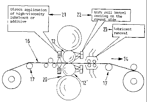
L'invention concerne un procédé et un dispositif pour établir une distribution de contraintes de traction ajustable, en particulier dans des zones de bord, lors du laminage à froid de bandes métalliques (16), en particulier de feuilles métalliques, afin de réduire le risque d'une accumulation de contraintes de traction trop élevée et les fissures en bord de bande qui présentent l'inconvénient de générer des fissures de bande lesquelles réduisent la production, ainsi que pour améliorer la surface des bandes et sa planéité, même pour une vitesse de déplacement de bande relativement élevée, et afin de réduire les largeurs de cisaillage des bandes. A cet effet, l'on applique au moins une mesure ou une combinaison d'au moins deux des mesures suivantes: a) séparer le processus de lubrification et le processus de refroidissement des rouleaux de travail, par lubrification côté entrée et refroidissement côté sortie; b) soumettre les bords des bandes à un processus supplémentaire de type pulvérisation des bords à chaud (HES), en particulier par pulvérisation (21), sur certaines zones, d'huile de laminage présentant des plages de températures différentes; c) utiliser une configuration de rodage spécifique des rouleaux de travail (12,12') dans la zone des bords de bande pour permettre, lors de la passe préalable, une accumulation partielle de matière qui, lors des passes subséquentes, forme un bord de bande plus long et contrecarre le risque d'une accumulation de contraintes de traction élevée.


Abrégé anglais


The invention relates to a method and a device for applying an adjustable
tensile-stress distribution, in particular in the edge regions during the cold-
rolling of metal strips (16), in particular metal foil, in order to reduce the
risk of an excessive build-up of tension and cracks at the edges of the strip,
which can lead as a negative consequence to cracks in the strip and to a
reduction in production, and in order to improve the surface of the strip and
its planarity, even for a relatively high strip displacement speed, and also
to reduce strip trimming widths. To achieve these aims, at least one or a
combination of two of the following measures are implemented: a) separation of
lubrication and cooling of the working rolls by lubricating on the run-in side
and cooling on the discharge side, b) additional influencing of the strip
edges using a hot edge spray", in particular by spraying (21) rolling oil with
differing temperatures in zones, c) use of a special cross-sectional
configuration of the working rolls (12, 12') in the vicinity of the strip
edges, which creates a partial material build-up during the blooming pass,
said build-up forming a longer strip edge with subsequent passes, thus
counteracting the risk of an excessive build-up of tensile stress.

Revendications

Note : Les revendications sont présentées dans la langue officielle dans laquelle elles ont été soumises.


We claim:
1. Method for applying an adjustable tensile stress
distribution in edge regions during the cold rolling of metal
strip, for the purpose of reducing a risk of excessive buildup
of tensile stress and a risk of edge cracks in the strip, which
can have a negative consequence of strip breakage and thus
reduced production, and for the purpose of improving the strip
surface and its flatness, even at relatively high strip running
speeds, and of reducing strip trimming widths, comprising the
step of:
(a) separation of lubrication and cooling of work rolls by
lubrication on a run-in side and cooling on a runout side, the
improvement comprising the additional steps of:
(b) additional influencing of the strip edges by hot edge
spray by spraying rolling oil with different temperature ranges
in different zones,
(c) the use of work rolls having a special cross-sectional
configuration in an area of the strip edges, which special
configuration is independent of the hot edge spray, for partial
material buildup during a roughing pass, which results in a
longer strip edge in following passes and counteracts the risk
of excessive buildup of tensile stress.
12

2. Method in accordance with claim 1, wherein a greater
diameter reduction of the work rolls is undertaken in the edge
region due to partial diameter increase during shaping by
inductive heating.
3. Method in accordance with claim 1, wherein the strip
tensile stress distribution is varied by a concavely bendable or
bent deflecting roll in such a way that the strip tensile stress
is reduced at the edges of the strip and increased in the center
of the strip.
4. Method in accordance with claim 1, wherein in roughing
passes, material is built up at the edges of the strip by edge
sprays with lubricants of relatively high viscosity.
5. Device for developing an adjustable tensile stress
distribution in edge regions during the cold rolling of metal
strip, the device comprising at least one spray nozzle system
(11, 11') on a run-in side for applying lubricant and means for
cooling the barrels of the work rolls on a runout side; wherein
at least two of the spray nozzle systems (11, 11') have
connections for separate spray medium supply lines (19, 19') for
spraying the lubricant in the form of rolling oil with different
temperatures in different zones (10, 10') of each work roll
(12); and that each of the work rolls (12, 12') has a special
cross section (13, 13') with increased diameters in the end
regions of the work rolls (12, 12') for the purpose of
13

lengthening the rolled strip edges with simultaneous reduction
of tensile stresses and reduction of long strip fibers in
regions near the edges of the strip.
6. Device in accordance with claim 5, comprising a
deflecting roll (15) that is convexly bendable or bent in the
strip running direction (14) and is arranged between guide rolls
(17) to change the tensile stress distribution of a strip (16)
before it enters a rolling stand (20).
7. Device in accordance with claim 5, wherein on the run-
in side of a rolling stand (20), it has means (21) for the
direct application of additive to the rolled strip (16), and on
the runout side of the work rolls (12, 12'), it has means (22)
for cooling the barrels of the work rolls and preferably
additional means (23, 23') for removal of the lubricant, which
advantageously spray the rolled strip (16) both from above the
strip and from below the strip with the associated spray media.
8. Device in accordance with claim 5, wherein it has a
device that removes coolant on the runout side of the stand
(20).
14

Description

Note : Les descriptions sont présentées dans la langue officielle dans laquelle elles ont été soumises.


CA 02537501 2009-03-06
METHOD AND DEVICE FOR APPLYING AN ADJUSTABLE TENSILE-STRESS
DISTRIBUTION, IN PARTICULAR IN THE EDGE REGIONS OF
COLD-ROLLED METAL STRIPS
The invention concerns a method for applying an adjustable
tensile stress distribution, especially in the edge regions of
the strip during the cold rolling of metal strip, for the
purpose of reducing the risk of excessive buildup of tensile
stress and the risk of edge cracks in the strip, which can have
the negative consequence of strip breakage and thus reduced
production, and for the purpose of improving the strip surface
and its flatness, even at relatively high strip running speeds,
and of reducing strip trimming widths. The invention also
concerns a device for carrying out this method.
The document EP 0 054 172 A2 discloses a method in which,
to achieve stress-free rolling of cold-rolled strip, the
coefficient of friction between the strip surfaces and the roll
barrel surfaces is influenced by the application of rolling
lubricants. These lubricants are supplied as a function of
partial tensile stresses determined after the last stand in
1

CA 02537501 2006-03-01
zones lying in the transverse direction of the strip. In this
regard, before the strip enters the roll gap, base oil of the
rolling lubricant is applied directly to the strip surfaces in
amounts determined by the determined partial tensile stresses
and in locally limited regions. The goal of this measure is to
apply the lubricant components locally to strips of the metal
strip that is to be rolled, so that the locally improved
lubrication reduces the rolling force there and thus also
reduces the local flattening of the roll. In addition, the
frictional heat introduced into the roll is reduced in these
places.
The document EP 0 367 967 Bl discloses a method and a
device in which the concentration of an emulsion of rolling oil
is systematically influenced, and the emulsion or dispersion is
caught and separated again after exiting the roll gap or running
off before the roll gap. This makes it possible to prepare the
emulsion or dispersion that is introduced into the roll gap
repeatedly and in a timely way with a certain concentration
before it is fed into the roll gap. The focus of this invention
is the current and active preparation of the emulsion and the
separation of the various media.
2

CA 02537501 2006-03-01
The document EP 1 188 494 Al describes a strip wiping
device, strip wiping method, rolling stand, and rolling method.
To improve the productivity of a cold-rolling installation, the
installation was equipped with a strip wiper.
At high-speed rolling of more than 700 m/min, which could
not be realized with conventional wiper rolls or tube wipers,
the productivity of the cold-rolling installation and the
surface quality of the strip were significantly improved by
adding the wiping device.
The document EP 0 672 471 B1 discloses a method and a
device for rolling strip, in which wear-resistant rolls with
increased radii of at least one of their end regions are used.
The rolls are axially displaced relative to each other in such a
way that the rolled strip is in contact over its width with the
regions of the rolls that have the smaller radii. With
increasing heating of the rolls and with thermal cambering of
the rolls, the rolls are displaced in opposite directions
relative to each other until areas of their greater radius are
moved over edge regions of the rolled strip. This eliminates
the cambering of the strip that would otherwise occur due to the
increasing thermal cambering.
3

CA 02537501 2006-03-01
The document DE 199 08 743 Al discloses a method and a
device for drying and keeping dry especially cold-rolled strip
in the runout area of cold-rolling mills and strip mills. To
dry and keep dry especially rolled strip, it is known that a
partition can be used to separate the dry area of the finish-
rolled strip from the damp area of the rolling stand. For this
purpose, the invention proposes contact-free sealing between the
partition and the strip by a cushion of compressed gas similar
to an air cushion, and a split flow, so that compressed gas from
blast nozzle bars with large numbers of blast nozzles is applied
to the surface of the strip at right angles from above and
below. Even at high strip speeds above 1,000 m/min, this
measure successfully prevents the penetration of rolling oil or
even emulsion, regardless of the strip width, and allows
contact-free strip drying.
The document DE 101 31 369 Al discloses a method and a
device for cooling and/or lubricating rolls, especially the work
rolls of a rolling stand, and a rolled strip conveyed through
and rolled between these rolls with the use of water in the form
of spray jets as the cooling medium and spray oil, oil/air
mixture; or oil/water mixture as the lubricant. In order to
improve the lubricating and cooling effects, the combined use of
4

CA 02537501 2006-03-01
supercooling the strip surface and roll surface and roll
lubrication on the input side of the stand is disclosed, in
which both media, i.e., water and lubricant, are separately fed
to the rolls and the rolled strip and applied to the roll
surface at different application points. Separate reservoirs
for water and lubricant and separate supply lines to the spray
bars for water and to the spray bars for the lubricant are
provided. This provides the great advantage of optimum use of
both the lubricating and cooling effect of the two media, water
and lubricant, and thus, at the same time, reduction of the
energy and power consumption due to the minimization of the
coefficients of friction on the rolls. The ground surface of
the roll withstands even the highest loads. The previously
observed material scaling of the rolls is prevented. The
surface of the rolling stock remains optimally smooth. Scale
inclusions and chatter marks on the strip surface are
eliminated.
Proceeding from the cited prior art, the objective of the
invention in the cold-rolling sector, especially in the aluminum
industry, but in certain cases in the steel industry and the
nonferrous metal industry as well, i's to minimize stiff strip
edges and long strip fibers near the edge that develop during

CA 02537501 2006-03-01
thin rolling, to reduce strip breakage, to save trimming, and
thus to improve the quality and quantity of production.
In accordance with the invention, these objectives with
respect to a method of the type specified in the introductory
clause of Claim 1 are achieved by the method specified in the
characterizing clause of Claim 1.
The measures of the invention demonstrably produce a
significant reduction of the risk of strip breakage and also
improve the strip surface.
Adjustable tensile stress distribution, especially in the
edge region of the strip, results in a higher material
throughput with a reduction of nonproductive time and an
increase in operating speed. In addition, there is an overall
significant improvement in flatness, production is increased,
and the amount of circulating rolling oil is reduced.
In a modification of the method of Claim 1, a greater
diameter reduction of the work rolls is undertaken in the edge
region due to a partial diameter increase during their shaping
by inductive heating.
In addition, use can be made of a measure by which the
strip tensile stress distribution is varied by a concavely
bendable or bent deflecting roll in such a way that the strip
6

CA 02537501 2006-03-01
tensile stress is reduced at the edges of the strip and
increased in the center of the strip.
Finally, use can be made of the additional measure that in
roughing passes material is built up at the edges of the strip
by edge sprays with lubricants of relatively high viscosity.
A device for applying an adjustable tensile stress
distribution, especially in edge regions during the cold rolling
of metal strip, preferably for carrying out the method of the
invention, characterized by spray nozzle systems arranged in at
least two separate zones with connections to separate spray
medium supply lines to different zones of each work roll and/or
by a special cross section with increased diameters in the end
regions of work rolls for the purpose of lengthening the strip
edges to be rolled with simultaneous reduction of tensile
stresses and reduction of long strip fibers in regions near the
edges of the strip. The advantages associated with these
measures were previously described in connection with the method
of the invention.
An advantageous modification of the device of the invention
has a deflecting roll that is convexly bendable or bent in the
strip running direction and is arranged between two guide rolls
to change the tensile stress distribution of a strip before it
7

CA 02537501 2009-03-06
enters a rolling.stand.
To supplement this feature, the device is also designed in
such a way that, on the run-in side of a rolling stand, it has
means for the direct application of additive, e.g., for
lubricating oil of relatively high viscosity, especially to the
rolled strip, and on the runout side of the work rolls, it has
means for cooling the barrels of the work rolls and preferably
additional means for removal of the lubricant, which means
advantageously spray the rolled strip both from above the strip
and from below the strip with the associated spray media.
Finally, the device of the invention has a device that
removes coolant on the runout side of the stand.
Accordingly, in one aspect the present invention provides
for a method for applying an adjustable tensile stress
distribution in edge regions during the cold rolling of metal
strip, for the purpose of reducing a risk of excessive buildup of
tensile stress and a risk of edge cracks in the strip, which can
have a negative consequence of strip breakage and thus reduced
production, and for the purpose of improving the strip surface and
its flatness, even at relatively high strip running speeds, and of
reducing strip trimming widths, comprising the step of: (a)
separation of lubrication and cooling of work rolls by lubrication
on a run-in side and cooling on a runout side, the improvement
comprising the additional steps of: (b) additional influencing of
8

CA 02537501 2009-03-06
the strip edges by hot edge spray by spraying rolling oil
with different temperature ranges in different zones, (c) the use
of work rolls having a special cross-sectional configuration in an
area of the strip edges, which special configuration is
independent of the hot edge spray, for partial material buildup
during a roughing pass, which results in a longer strip edge in
following passes and counteracts the risk of excessive buildup of
tensile stress.
In another aspect, the present invention provides a device
for developing an adjustable tensile stress distribution in edge
regions during the cold rolling of metal strip, the device
comprising at least one spray nozzle system (11, 11') on a run-in
side for applying lubricant and means for cooling the barrels of
the work rolls on a runout side; wherein at least two of the spray
nozzle systems (11, 11') have connections for separate spray
medium supply lines (19, 19') for spraying the lubricant in the
form of rolling oil with different temperatures in different zones
(10, 10') of each work roll (12); and that each of the work rolls
(12, 12') has a special cross section (13, 13') with increased
diameters in the end regions of the work rolls (12, 12') for the
purpose of lengthening the rolled strip edges with simultaneous
reduction of tensile stresses and reduction of long strip fibers
in regions near the edges of the strip.
8a

CA 02537501 2009-03-06
BRIEF DESCRIPTION OF THE DRAWINGS
Further details, features, and advantages of the invention
are explained below with reference to the specific embodiment
of the invention that is illustrated in the drawings.
-- Figure 1 shows a device for hot edge spray at the roll
edge.
- Figure 2 shows a special cross section for work rolls.
-- Figure 3 shows a convexly bendable or bent deflecting
roll in a side view.
-- Figure 4 shows the top view of the deflecting roll
of Figure 3.
8b

CA 02537501 2006-03-01
-- Figure 5 shows a side view of an installation of the
invention with direct application of lubricant to the rolled
strip, roll cooling on the runout side, and lubricant removal.
Figure 1 shows part of a device for applying an adjustable
tensile stress distribution, especially in the edge regions
during the cold rolling of metal strip, with spray nozzle
systems 11, 11' arranged in at least two separate zones 10, 10'
with connections to separate spray medium supply lines 19, 19'
to different zones 10, 10' of each work roll 12. In addition,
there is the possibility of partial inductive heating of the
work roll in a way that is already well known.
Figure 2 shows a pair of work rolls 12, 12', each of which
has a special cross section 13, 13' in one end region with
.increased diameters in the end regions to lengthen the strip
edges to be rolled with simultaneous reduction of tensile
stresses and reduction of long strip fibers.
Figures 3 and 4 show a side view and a top view,
respectively, of a system for lengthening the tensile stress
distribution by means of the strip width in shaping passes.
This is accomplished by a variable angle of wrap W for different
strip thicknesses:
9

CA 02537501 2006-03-01
1-6 pm with W = 60-90
8-20 pm with W = 45-60
> 20 pm with W = 45 and higher
for metal foils with W = 15-20
Figure 5 shows a side view of an installation of the
invention, with an uncoiler on the left side and a coiler on the
right side, guide devices for the rolled strip 16 in the strip
running direction 14, means 21 for the direct application of
high-viscosity lubricant or additive on the strip run-in side,
means 22 for cooling the barrels of the work rolls on the runout
side, and means 23 for the removal of lubricant on the runout
side. A buildup of material on the strip edge during the
roughing passes and thus a buildup of material on the strip edge
during the shaping passes are achieved with the aid of direct
application of additive on the run-in side and roll cooling on
the runout side.

CA 02537501 2006-03-01
List of Reference Numbers
10, 10' spray zone
11, 11' spray nozzle system
12, 12' work rolls
14 strip running direction
15 deflecting roll
16 strip
17 guide roll
19, 19' spray medium supply lines
20 rolling stand
21 additive application
22 roll barrel coolant
23 lubricant removal
11

Dessin représentatif
Une figure unique qui représente un dessin illustrant l'invention.
États administratifs

2024-08-01 : Dans le cadre de la transition vers les Brevets de nouvelle génération (BNG), la base de données sur les brevets canadiens (BDBC) contient désormais un Historique d'événement plus détaillé, qui reproduit le Journal des événements de notre nouvelle solution interne.

Veuillez noter que les événements débutant par « Inactive : » se réfèrent à des événements qui ne sont plus utilisés dans notre nouvelle solution interne.

Pour une meilleure compréhension de l'état de la demande ou brevet qui figure sur cette page, la rubrique Mise en garde , et les descriptions de Brevet , Historique d'événement , Taxes périodiques et Historique des paiements devraient être consultées.

Historique d'événement

Description Date
Le délai pour l'annulation est expiré 2020-08-31
Inactive : COVID 19 - Délai prolongé 2020-08-19
Représentant commun nommé 2019-10-30
Lettre envoyée 2019-08-27
Accordé par délivrance 2010-10-19
Inactive : Page couverture publiée 2010-10-18
Préoctroi 2010-06-18
Inactive : Taxe finale reçue 2010-06-18
Un avis d'acceptation est envoyé 2010-05-27
Lettre envoyée 2010-05-27
Un avis d'acceptation est envoyé 2010-05-27
Inactive : Approuvée aux fins d'acceptation (AFA) 2010-05-25
Lettre envoyée 2009-08-31
Lettre envoyée 2009-04-14
Modification reçue - modification volontaire 2009-03-06
Exigences pour une requête d'examen - jugée conforme 2009-03-04
Toutes les exigences pour l'examen - jugée conforme 2009-03-04
Requête d'examen reçue 2009-03-04
Inactive : IPRP reçu 2007-06-11
Lettre envoyée 2006-10-16
Inactive : Correspondance - Formalités 2006-09-06
Inactive : Transfert individuel 2006-09-06
Inactive : Page couverture publiée 2006-05-17
Inactive : Lettre de courtoisie - Preuve 2006-05-09
Inactive : Notice - Entrée phase nat. - Pas de RE 2006-05-04
Demande reçue - PCT 2006-03-23
Exigences pour l'entrée dans la phase nationale - jugée conforme 2006-03-01
Demande publiée (accessible au public) 2005-03-17

Historique d'abandonnement

Il n'y a pas d'historique d'abandonnement

Taxes périodiques

Le dernier paiement a été reçu le 2010-07-23

Avis : Si le paiement en totalité n'a pas été reçu au plus tard à la date indiquée, une taxe supplémentaire peut être imposée, soit une des taxes suivantes :

  • taxe de rétablissement ;
  • taxe pour paiement en souffrance ; ou
  • taxe additionnelle pour le renversement d'une péremption réputée.

Les taxes sur les brevets sont ajustées au 1er janvier de chaque année. Les montants ci-dessus sont les montants actuels s'ils sont reçus au plus tard le 31 décembre de l'année en cours.
Veuillez vous référer à la page web des taxes sur les brevets de l'OPIC pour voir tous les montants actuels des taxes.

Titulaires au dossier

Les titulaires actuels et antérieures au dossier sont affichés en ordre alphabétique.

Titulaires actuels au dossier
SMS SIEMAG AKTIENGESELLSCHAFT
Titulaires antérieures au dossier
HANS-PETER RICHTER
HARTMUT PAWELSKI
JUERGEN KLOECKNER
LUDWIG WEINGARTEN
RALF OHRNDORF
THORSTEN BODE
Les propriétaires antérieurs qui ne figurent pas dans la liste des « Propriétaires au dossier » apparaîtront dans d'autres documents au dossier.
Documents

Pour visionner les fichiers sélectionnés, entrer le code reCAPTCHA :


Pour visualiser une image, cliquer sur un lien dans la colonne description du document (Temporairement non-disponible). Pour télécharger l'image (les images), cliquer l'une ou plusieurs cases à cocher dans la première colonne et ensuite cliquer sur le bouton "Télécharger sélection en format PDF (archive Zip)" ou le bouton "Télécharger sélection (en un fichier PDF fusionné)".

Liste des documents de brevet publiés et non publiés sur la BDBC .

Si vous avez des difficultés à accéder au contenu, veuillez communiquer avec le Centre de services à la clientèle au 1-866-997-1936, ou envoyer un courriel au Centre de service à la clientèle de l'OPIC.

({010=Tous les documents, 020=Au moment du dépôt, 030=Au moment de la mise à la disponibilité du public, 040=À la délivrance, 050=Examen, 060=Correspondance reçue, 070=Divers, 080=Correspondance envoyée, 090=Paiement})


Description du
Document 
Date
(aaaa-mm-jj) 
Nombre de pages   Taille de l'image (Ko) 
Abrégé 2006-02-28 2 114
Description 2006-02-28 11 298
Revendications 2006-02-28 3 90
Dessins 2006-02-28 4 56
Dessin représentatif 2006-05-08 1 11
Revendications 2009-03-05 3 89
Description 2009-03-05 13 355
Dessin représentatif 2010-09-29 1 13
Avis d'entree dans la phase nationale 2006-05-03 1 206
Courtoisie - Certificat d'enregistrement (document(s) connexe(s)) 2006-10-15 1 105
Accusé de réception de la requête d'examen 2009-04-13 1 176
Avis du commissaire - Demande jugée acceptable 2010-05-26 1 167
Avis concernant la taxe de maintien 2019-10-07 1 177
PCT 2006-02-28 1 23
Correspondance 2006-05-03 1 28
Correspondance 2006-09-05 1 41
PCT 2006-03-01 5 157
Taxes 2007-08-09 1 52
Taxes 2008-08-13 1 54
Correspondance 2010-06-17 1 49
Correspondance 2010-06-17 1 54