Sélection de la langue

Search

Sommaire du brevet 2537838 

Énoncé de désistement de responsabilité concernant l'information provenant de tiers

Une partie des informations de ce site Web a été fournie par des sources externes. Le gouvernement du Canada n'assume aucune responsabilité concernant la précision, l'actualité ou la fiabilité des informations fournies par les sources externes. Les utilisateurs qui désirent employer cette information devraient consulter directement la source des informations. Le contenu fourni par les sources externes n'est pas assujetti aux exigences sur les langues officielles, la protection des renseignements personnels et l'accessibilité.

Disponibilité de l'Abrégé et des Revendications

L'apparition de différences dans le texte et l'image des Revendications et de l'Abrégé dépend du moment auquel le document est publié. Les textes des Revendications et de l'Abrégé sont affichés :

  • lorsque la demande peut être examinée par le public;
  • lorsque le brevet est émis (délivrance).
(12) Brevet: (11) CA 2537838
(54) Titre français: CLAPET
(54) Titre anglais: CHECK VALVE
Statut: Octroyé
Données bibliographiques
(51) Classification internationale des brevets (CIB):
  • F16K 15/02 (2006.01)
(72) Inventeurs :
  • MACKAL, GLENN H. (Etats-Unis d'Amérique)
(73) Titulaires :
  • HALKEY-ROBERTS CORPORATION (Etats-Unis d'Amérique)
(71) Demandeurs :
  • HALKEY-ROBERTS CORPORATION (Etats-Unis d'Amérique)
(74) Agent: NORTON ROSE FULBRIGHT CANADA LLP/S.E.N.C.R.L., S.R.L.
(74) Co-agent:
(45) Délivré: 2012-11-06
(86) Date de dépôt PCT: 2004-09-08
(87) Mise à la disponibilité du public: 2005-03-24
Requête d'examen: 2009-09-01
Licence disponible: S.O.
(25) Langue des documents déposés: Anglais

Traité de coopération en matière de brevets (PCT): Oui
(86) Numéro de la demande PCT: PCT/US2004/029072
(87) Numéro de publication internationale PCT: WO2005/026593
(85) Entrée nationale: 2006-03-02

(30) Données de priorité de la demande:
Numéro de la demande Pays / territoire Date
60/501,296 Etats-Unis d'Amérique 2003-09-08
10/935,937 Etats-Unis d'Amérique 2004-09-08

Abrégés

Abrégé français

La présente invention a trait à un clapet comportant un champignon sollicité par un ressort conique pour l'obturation étanche uniforme annulaire autour de toute sa périphérie pour assurer une pression d'ouverture plus uniforme autour de toute sa périphérie. La pression d'ouverture peut être ajustée au moyen d'une platine réglable qui réduit la longueur du ressort conique, accroissant ainsi la quantité de force exercée par le ressort sur le champignon en engagement étanche, augmentant ainsi la pression d'ouverture.


Abrégé anglais


A check valve comprising a poppet (30) urged by a conical spring (50) to
annularly seal uniformly around its entire periphery to assure more uniform
cracking pressure about its entire periphery. To insure uniform sealing of the
poppet (30) against a seat (36) the conical spring (50) has a smallest coil
(50S) in engagement with a center protrusion (42) of the poppet (30) to permit
the protrusion (42) to pivot relative to the conical spring (50).

Revendications

Note : Les revendications sont présentées dans la langue officielle dans laquelle elles ont été soumises.


1. A check valve comprising in combination:
a body;
a cap affixed to said body;
a poppet positioned within said body, said poppet having
an annular sealing member for annular sealing engagement with a seat
formed within said body, said poppet further including a center protrusion
extending interiorly therefrom; and
a conical spring entrained between said cap and said
protrusion;
whereby said protrusion may pivot relative to said conical
spring to assure uniform sealing of said sealing member with said annular
seat.

2. The check valve as set forth in Claim 1, wherein said cap
having comprises a plurality of flow openings about its periphery allowing
fluid to flow through said body to then be exhausted from the check valve.

3. The check valve as set forth in Claim 1, wherein said body
is connected about an opening in an inflatable through the use of a threaded
flange that sealingly captures an edge of said opening in said inflatable.

4. The check valve as set forth in Claim 1, wherein said
poppet includes an annular groove in which is positioned an annular sealing

-12-


member.

5. The check valve as set forth in Claim 1, wherein said
poppet comprises a concave portion having an upstanding protrusion
extending from the inside center thereof.

6. The check valve as set forth in Claim 5, wherein said
protrusion comprises interior webs forming a semi-spherical outer
configuration.

7. The check valve as set forth in Claim 5, wherein said
poppet comprises exterior webs, slightly tapered inwardly, from a lumen of
said body.

8. The check valve as set forth in Claim 1, wherein said cap
comprises a plurality of tabs that snap into corresponding slots formed in the
outer periphery of said body to securely retain said cap to said body.

9. The check valve as set forth in Claim 1, wherein said cap
comprises a plurality of downwardly extending legs to entrain said poppet
therebetween.

10. The check valve as set forth in Claim 1, wherein said
conical spring includes an uppermost largest diameter coil captured by an
annular step formed in the underside of the cap.

11. The check valve as set forth in Claim 1, wherein said


-13-


conical spring includes a lowermost smallest diameter coil dimensioned to be
appreciably less in diameter than an outer diameter of said center protrusion
such that when said coil spring is seated thereon, said poppet is allowed to
pivot universally in all directions.

12. The check valve as set forth in Claim 1, further including
an adjustable plate positioned between an uppermost larger diameter spring
coil of said conical spring and an underside of cap.

13. The check valve as set forth in Claim 12, wherein said
adjustable plate comprises a center boss with external threads for threaded
engagement with a threaded hole formed in a center of said cap.

14. The check valve as set forth in Claim 13, wherein said
boss comprises an indentation for receiving a hex or other tool allowing
rotation thereof to cause said plate to move inwardly to further compress said
conical spring and thereby increase the cracking pressure.

15. The check valve as set forth in Claim 13, wherein an
outer periphery of said adjustable plate comprises radial protuberances that
engage into openings of said cap to provide indexing of said adjustable plate
to adjust the cracking pressure.

16. The check valve as set forth in Claim 15, wherein said
protuberances are asymmetrically positioned to provide accurate indexing.

-14-


17. The check valve as set forth in Claim 1, wherein said
protrusion comprises a conical apex point on which is seated a balance plate.

18. The check valve as set forth in Claim 17, wherein said
balance plate comprises a center seat that receives said conical apex point.

19. A check valve comprising in combination:
a body;
a cap affixed to said body, said cap comprising a plurality of flow
openings about its periphery allowing fluid to flow through said body to then
be exhausted from the check valve and a plurality of tabs that snap into
corresponding slots formed in an outer periphery of said body to securely
retain said cap to said body;
a poppet positioned within said body, said poppet including
an annular groove in which is positioned an annular sealing
member for annular sealing engagement with a seat formed within said body,
a center protrusion extending interiorly from said poppet, said
protrusion comprising a semi-spherical outer configuration,
a concave portion having an upstanding protrusion extending
from the inside center thereof,
exterior webs;
said cap comprising a plurality of downwardly extending legs to

-15-


entrain said poppet therebetween;
a conical spring entrained between said cap and said protrusion,
said conical spring including an uppermost largest diameter coil captured by
an annular step formed in the underside of said cap and a lowermost smallest
diameter coil dimensioned to be appreciably less in diameter than an outer
diameter of said center protrusion such that when said coil spring is seated
thereon, said poppet is allowed to pivot universally in all directions,
whereby said protrusion may pivot relative to said conical spring
to assure uniform sealing of said sealing member with said annular seat.

20. A check valve comprising in combination:
a body;
a cap affixed to said body, said cap comprising a plurality of flow
openings about its periphery allowing fluid to flow through said body to then
be exhausted from the check valve and a plurality of tabs that snap into
corresponding slots formed in an outer periphery of said body to securely
retain said cap to said body, said cap further including an adjustable plate
positioned on an underside of said cap, said adjustable plate comprising a
center boss with external threads for threaded engagement with a threaded
hole formed in a center of said cap, said adjustable plate further comprising
radial protuberances that engage into said openings of said cap to provide

-16-


indexing of said adjustable plate to adjust the cracking pressure;
a poppet positioned within said body, said poppet including
an annular groove in which is positioned an annular sealing
member for annular sealing engagement with a seat formed within said body,
a center protrusion extending interiorly from said poppet, said
protrusion comprising a semi-spherical outer configuration,
a concave portion having an upstanding protrusion extending
from the inside center thereof,
exterior webs;
a conical spring entrained between said adjustable plate and
said protrusion, said conical spring including an uppermost largest diameter
coil engaging an underside of said adjustable plate and a lowermost smallest
diameter coil dimensioned to be appreciably less in diameter than an outer
diameter of said center protrusion such that when said coil spring is seated
thereon, said poppet is allowed to pivot universally in all directions,
whereby said protrusion may pivot relative to said conical spring to assure
uniform sealing of said sealing member with said annular seat.

-17-

Description

Note : Les descriptions sont présentées dans la langue officielle dans laquelle elles ont été soumises.


CA 02537838 2011-11-01

WO 2005/026593 PC'T'/U S2004/ 029072
CHECK VALVE

BACKGROUND OF THE INVENTION
Field of the Invention

This invention relates to check valves. More particularly, this
invention relates to check valves having presettable and adjustable
cracking pressures.

Description of the Background Art

Presently, there exist many types of check valves designed to
allow the flow of a fluid such as a gas in one direction but to block or
"check"
the flow of the fluid in the opposite direction. The amount of fluid force
required to open the poppet of the valve in the un-checked direction is often
referred to as the cracking pressure. Typically, the cracking pressure of a
check valve is determined by the spring constant of the internal spring which
constantly urges the poppet into a sealing position until unseated therefrom
once the cracking pressure is attained.

A predetermined cracking pressure of a check valve is desired
when check valves are used in conjunction with inflatable articles such as
life
vests and life rafts. Specifically, a check valve having a predetermined


CA 02537838 2006-03-02
WO 2005/026593 PCT/US2004/029072
cracking pressure allows the inflatable to be inflated by means of a gas
cartridge or the like to assure that the inflatable is inflated to a preset
internal pressure. Thus, by allowing excess gas to be exhausted, over-
capacity gas cartridges can be employed to inflate the inflatable to ensure
that the inflatable is fully inflated to a preset internal pressure in all
environments.

Therefore, it is an object of this invention to provide an
improvement which overcomes the aforementioned inadequacies of the
prior art devices and provides an improvement which is a significant
contribution to the advancement of the oral inflation art.

Another object of this invention is to provide a check valve
having an increased flow rate.

Another object of this invention is to provide a check valve
having a structure composed of a minimal number of parts to increase its
reliability while decreasing cost of manufacture and assembly.

Another object of this invention is to provide a check valve
having a design that equalizes the sealing force of the poppet around its
entire periphery to assure that the check valve is cracked uniformly about
the periphery of the poppet.

The foregoing has outlined some of the pertinent objects of
the invention. These objects should be construed to be merely illustrative
of some of the more prominent features and applications of the intended

-2-


CA 02537838 2006-03-02
WO 2005/026593 PCT/US2004/029072
invention. Many other beneficial results can be attained by applying the
disclosed invention in a different manner or modifying the invention
within the scope of the disclosure. Accordingly, other objects and a fuller
understanding of the invention may be had by referring to the summary of
the invention and the detailed description of the preferred embodiment in
addition to the scope of the invention defined by the claims taken in
conjunction with the accompanying drawings.

-3-


CA 02537838 2006-03-02
WO 2005/026593 PCT/US2004/029072
SUMMARY OF THE INVENTION

For the purpose of summarizing this invention, this invention
comprises a check valve having a simple design with fewer parts than
conventional prior art check valves to achieve increased reliability while
reducing manufacturing and assembly costs. The check valve of the
invention further achieves an increased flow rate upon cracking due to its
simplistic yet ingenious design.

Finally, the poppet of the check valve of the invention cooperates
with a conical spring to assure that it seals uniformly around its entire
periphery facilitating more uniform cracking pressure about its entire
periphery.

In another embodiment of the check valve of the invention, the
cracking pressure is adjustable by means of a threaded adjustable plate
which cooperates with the conical spring to reduce the length thereof and
thereby increase the amount of force exerted by the spring onto the poppet
into sealing engagement, thereby increasing the cracking pressure.

The foregoing has outlined rather broadly the more pertinent
and important features of the present invention in order that the detailed
description of the invention that follows may be better understood so that the
present contribution to the art can be more fully appreciated. Additional

-4-


CA 02537838 2006-03-02
WO 2005/026593 PCT/US2004/029072
features of the invention will be described hereinafter which form the subject
of the claims of the invention. It should be appreciated by those skilled in
the
art that the conception and the specific embodiment disclosed may be readily
utilized as a basis for modifying or designing other structures for carrying
out
the same purposes of the present invention. It should also be realized by

those skilled in the art that such equivalent constructions do not depart from
the spirit and scope of the invention as set forth in the appended claims.

-5-


CA 02537838 2006-03-02
WO 2005/026593 PCT/US2004/029072
BRIEF DESCRIPTION OF THE DRAWINGS

For a fuller understanding of the nature and objects of the
invention, reference should be had to the following detailed description taken
in connection with the accompanying drawings in which:

Fig. 1 is a perspective view of the first embodiment of the check
valve of the invention;

Fig. 2 is a perspective view, partially cut-away, of the first
embodiment of the invention;

Fig. 3 is a perspective view, partially cut-away, of the first
embodiment of the invention;

Fig. 4 is a perspective view of the second embodiment of the
check valve of the invention;

Fig. 5 is a cross-sectional view of Fig. 5 along lines 5-5; and
Fig. 6 illustrates an alternative embodiment of centering the
conical spring to assure uniform sealing of the poppet.

Similar reference characters refer to similar parts throughout
the several views of the drawings.

-6-


CA 02537838 2006-03-02
WO 2005/026593 PCT/US2004/029072
DETAILED DESCRIPTION OF THE PREFERRED EMBODIMENT
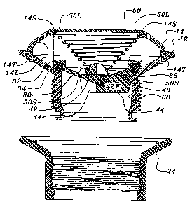
The check valve 10 of the invention comprises a body 12 to

which is mounted a cap 14 having a plurality of flow openings 16 about its
periphery allowing fluid to flow in the direction of arrows 18 through the
body 12 to then be exhausted from the check valve 10 via openings 16 as
shown by arrows 20.

Body 12 may be connected about an opening in an inflatable,
shown in phantom by reference numeral 22, through the use of a threaded
flange 24 that sealingly captures the edge 26 of the opening in the inflatable
22.

As shown in Figs. 2 and 3, check valve 10 of the invention
comprises a poppet 30 having an annular groove 32 in which is positioned an
annular O-ring 34 that seats on an annular seat 36 formed at the end of the
lumen 38 of the body 12.

The poppet 30 includes a concave portion 46 having an
upstanding protrusion 42 extending from the inside center thereof.
Protrusion 42 comprises four interior webs 42W positioned at 90 degree
intervals and forming a semi-spherical outer configuration. Poppet 30
further comprises three exterior webs 44, slightly tapered inwardly, from the
lumen 38 of the body 12.

-7-


CA 02537838 2006-03-02
WO 2005/026593 PCT/US2004/029072
Cap 14 comprises a plurality of tabs 14T that snap into
corresponding slots formed in the outer periphery of the cap 12 to securely
retain the cap 14 into position. Cap 14 further comprises a plurality of
downwardly extending legs 14L, such as three positioned at 120 degree
intervals, to entrain the poppet 30 therebetween. The legs 14L coupled with
the exterior webs 44 assure that the poppet 30 may reciprocate upwardly
within cap 14 without tilting sideways out of alignment where it may
potentially jam.

Finally, the check valve 10 of the invention comprises a conical
spring 50 having its uppermost largest diameter coil 50L captured by an
annular step 14S formed in the underside of the cap 14. The lowermost
smallest diameter coil 50S is dimensioned to be appreciably less in diameter
than the outer diameter of the protrusion 42 such that when the coil 50S is
seated thereon, poppet 30 is allowed to pivot universally in all directions.

The ability of the poppet 30 to pivot universally by virtue of the protrusion
42
pivoting within the coil 50S, assures that the O-ring 34 of the poppet 30 will
be forced into sealing engagement with the annular seat 36 in a highly
uniform manner about its entire periphery. Consequently, uniform cracking
of the poppet 30 about its entire periphery is achieved.

Referring now to Figs. 4 and 5, the second embodiment of the
-8-


CA 02537838 2006-03-02
WO 2005/026593 PCT/US2004/029072
check valve 10 of the invention comprises a similar body 12 with a cap 14
having flow openings 20 allowing fluid flow 18 to flow through the valve 10 in
the unchecked flow direction. Similarly, the second embodiment of the check
valve 10 of the invention comprises a conical spring 50 entrained between the
cap 14 and a poppet 30 to urge its O-ring 34 in sealing engagement with the
annular seat 36.

The poppet 30 further includes exterior webs 44 which prevent
the poppet from becoming canted with the lumen 38. However, due to the
specific configuration of the cap 14, in the second embodiment, the downward
depending legs 14L of the cap 14 of the first embodiment need not be included
since the annular groove 32 moves in alignment with the lumen 52 of the cap
14.

In the second embodiment, poppet 30 similarly includes an
upstanding center protrusion 42 with four webs 42W forming an outer semi-
spherical configuration on which is seated the lowermost smaller diameter
coil 50S of the spring 50.

Unlike the first embodiment, the second embodiment of the check
valve 10 comprises an adjustable plate 60 having a center boss 62 with
external threads 64 for threaded engagement with a threaded hole 66 formed
in the center of the cap 14. Boss 62 may be provided with a hex indentation 63
-9-


CA 02537838 2006-03-02
WO 2005/026593 PCT/US2004/029072
for receiving a hex or other tool.

Plate 60 extends in a somewhat planar configuration from the
boss 62 to a position between the uppermost larger diameter spring coil 50L
and the underside of cap 14. Upon rotation of the boss 62 in a clockwise
direction, plate 60 is caused to move inwardly to further compress the conical
spring and thereby increase the cracking pressure of the check valve 10. The
outer periphery of the plate 60 may be provided with radial protuberances
60P to engage into openings 20 and provide indexing of the plate 60 as the
plate 60 is rotated to adjust the cracking pressure. The protuberances 60P
may be of the same width as the openings 20 or, if smaller, may be
asymmetrically positioned to provide accurate indexing.

Fig. 6 illustrates an alternative embodiment for free-floating of
the poppet 30 to assure uniform annular indexing of its O-ring 34 on annular
seat 36. Specifically, protrusion 42 is configured to achieve a conical apex
point for universal engagement into a corresponding center seat 62 formed in
a balance plate 60. The balance plate 60 assures that only a central force is
exerted onto the poppet 30 thereby achieving uniform annular sealing.

The present disclosure includes that contained in the appended
claims, as well as that of the foregoing description. Although this invention
has been described in its preferred form with a certain degree of

-10-


CA 02537838 2006-03-02
WO 2005/026593 PCT/US2004/029072
particularity, it is understood that the present disclosure of the preferred
form has been made only by way of example and that numerous changes in
the details of construction and the combination and arrangement of parts
may be resorted to without departing from the spirit and scope of the
invention.

Now that the invention has been described,
WHAT IS CLAIMED IS:

-11-

Dessin représentatif
Une figure unique qui représente un dessin illustrant l'invention.
États administratifs

Pour une meilleure compréhension de l'état de la demande ou brevet qui figure sur cette page, la rubrique Mise en garde , et les descriptions de Brevet , États administratifs , Taxes périodiques et Historique des paiements devraient être consultées.

États administratifs

Titre Date
Date de délivrance prévu 2012-11-06
(86) Date de dépôt PCT 2004-09-08
(87) Date de publication PCT 2005-03-24
(85) Entrée nationale 2006-03-02
Requête d'examen 2009-09-01
(45) Délivré 2012-11-06

Historique d'abandonnement

Il n'y a pas d'historique d'abandonnement

Historique des paiements

Type de taxes Anniversaire Échéance Montant payé Date payée
Le dépôt d'une demande de brevet 400,00 $ 2006-03-02
Taxe de maintien en état - Demande - nouvelle loi 2 2006-09-08 100,00 $ 2006-03-02
Enregistrement de documents 100,00 $ 2006-05-29
Taxe de maintien en état - Demande - nouvelle loi 3 2007-09-10 100,00 $ 2007-08-21
Taxe de maintien en état - Demande - nouvelle loi 4 2008-09-08 100,00 $ 2008-08-28
Taxe de maintien en état - Demande - nouvelle loi 5 2009-09-08 200,00 $ 2009-08-25
Requête d'examen 800,00 $ 2009-09-01
Taxe de maintien en état - Demande - nouvelle loi 6 2010-09-08 200,00 $ 2010-08-19
Taxe de maintien en état - Demande - nouvelle loi 7 2011-09-08 200,00 $ 2011-08-18
Taxe finale 300,00 $ 2012-07-03
Taxe de maintien en état - Demande - nouvelle loi 8 2012-09-10 200,00 $ 2012-08-20
Taxe de maintien en état - brevet - nouvelle loi 9 2013-09-09 200,00 $ 2013-08-19
Taxe de maintien en état - brevet - nouvelle loi 10 2014-09-08 250,00 $ 2014-09-02
Taxe de maintien en état - brevet - nouvelle loi 11 2015-09-08 250,00 $ 2015-09-08
Taxe de maintien en état - brevet - nouvelle loi 12 2016-09-08 250,00 $ 2016-09-06
Taxe de maintien en état - brevet - nouvelle loi 13 2017-09-08 250,00 $ 2017-09-05
Taxe de maintien en état - brevet - nouvelle loi 14 2018-09-10 250,00 $ 2018-09-04
Taxe de maintien en état - brevet - nouvelle loi 15 2019-09-09 450,00 $ 2019-08-30
Taxe de maintien en état - brevet - nouvelle loi 16 2020-09-08 450,00 $ 2020-09-04
Taxe de maintien en état - brevet - nouvelle loi 17 2021-09-08 459,00 $ 2021-09-03
Taxe de maintien en état - brevet - nouvelle loi 18 2022-09-08 458,08 $ 2022-09-02
Taxe de maintien en état - brevet - nouvelle loi 19 2023-09-08 473,65 $ 2023-09-01
Titulaires au dossier

Les titulaires actuels et antérieures au dossier sont affichés en ordre alphabétique.

Titulaires actuels au dossier
HALKEY-ROBERTS CORPORATION
Titulaires antérieures au dossier
MACKAL, GLENN H.
Les propriétaires antérieurs qui ne figurent pas dans la liste des « Propriétaires au dossier » apparaîtront dans d'autres documents au dossier.
Documents

Pour visionner les fichiers sélectionnés, entrer le code reCAPTCHA :


Pour visualiser une image, cliquer sur un lien dans la colonne description du document. Pour télécharger l'image (les images), cliquer l'une ou plusieurs cases à cocher dans la première colonne et ensuite cliquer sur le bouton "Télécharger sélection en format PDF (archive Zip)" ou le bouton "Télécharger sélection (en un fichier PDF fusionné)".

Liste des documents de brevet publiés et non publiés sur la BDBC .

Si vous avez des difficultés à accéder au contenu, veuillez communiquer avec le Centre de services à la clientèle au 1-866-997-1936, ou envoyer un courriel au Centre de service à la clientèle de l'OPIC.


Description du
Document 
Date
(yyyy-mm-dd) 
Nombre de pages   Taille de l'image (Ko) 
Revendications 2006-03-02 6 206
Abrégé 2006-03-02 2 81
Description 2006-03-02 11 339
Dessins 2006-03-02 6 232
Dessins représentatifs 2006-05-10 1 22
Page couverture 2006-05-11 1 49
Description 2011-11-01 11 339
Page couverture 2012-10-10 1 50
Correspondance 2008-04-15 20 906
Correspondance 2006-05-08 1 26
Cession 2006-05-29 4 138
PCT 2006-03-02 2 83
Cession 2006-03-02 4 130
PCT 2006-03-03 3 135
Correspondance 2008-07-28 1 31
Poursuite-Amendment 2009-09-01 3 88
Poursuite-Amendment 2011-05-11 2 44
Poursuite-Amendment 2011-11-01 5 169
Correspondance 2012-07-03 3 121