Note : Les descriptions sont présentées dans la langue officielle dans laquelle elles ont été soumises.
CA 02537845 2006-02-28
1
PICTURE LEVELING/POSITIONING TEMPLATE
BACKGROUND OF THE INVENTION
1. Field of the Invention
The present invention relates generally to picture leveling/positioning and,
more specifically, to an inexpensive, reusable, and compact picture
leveling/positioning template where the design of the device would allow the
user to
arrange picture frames, shadow boxes, shelving, signage, or any objects with 2
or 3
dimensions that could be mounted on a wall in a preferred arrangement in
limitless
aesthetic combinations on a vertical surface of any size or slope and curved
wall
surfaces.
The template also has multiple leveling guides to assist the user in leveling
and spacing picture frames horizontally and vertically on any vertical
surface.
The invention is a three part inexpensive compact kit comprised of a planar
pliable material with multiple leveling lines inscribed thereon, a non-shear
adhesive,
and bubble levels with a non-shear adhesive.
2. Description of the Prior Art
There are other level devices designed for leveling pictures. Typical of these
is U.S. Pat. No. 2,667,704 issued to Carl H. Dunn on Mar. 18, 1952.
CA 02537845 2006-02-28
2
Another patent was issued to Gary E Mallory on Sep. 5, 1967 as U.S. Pat.
No. 3,339,302. Yet another U.S. Pat. No. 3,523,382 was issued to Ronald L.
Dreyer
on Aug. 11, 1970 and still yet another was issued on Jul. 18, 1978 to Bruce L.
Hollander as U.S. Pat. No. 4,100,681.
Another patent was issued to Stephen R. Berndt on Jun. 24, 1980 as U.S.
Pat. No. 4,208,802. Yet another U.S. Pat. No. 4,936,033 was issued to Mark
Lacko
on June 26, 1990. Another was issued to Michael Kane on Dec. 11, 1990 as U.S.
Pat. No. 4,976,055 and still yet another was issued on Nov. 7, 1995 to Richard
A.
Leeds as U.S. Pat. No. 5,463,817.
In a bracket for leveling picture frames and the like, the combination which
comprises a plate having an extended edge and with upwardly extended sections
of
unequal length on the ends, arms of unequal length with hooks extended from
the
upper ends extended upwardly from the sections at the ends of the plate, and
means hinging said arms to the upwardly extended sections at the ends of the
plate.
A frame structure for photographs, comprising: (a) a rectangular frame
defining a central opening; (b) means for positioning a photograph in said
opening;
(c) a raised rim bordering said frame and having a set of slots therein
defining a
common plane parallel to, but offset from said frame; (d) a set of tongues
extending
outwardly from said rim in the same plane as said slots, said tongues and
slots
being so located as to permit the tongues of one frame structure to enter the
slots of
a companion frame structure thereby to join said frame structures.
Individual frames are provided with hooks or clamps which cooperate with
holes or slots respectively in similar frames to secure adjacent frames
together in
various arrangements. A photograph, glass and backing are retained in position
within the individual frames by an integrally formed, resilient clip which
extends from
CA 02537845 2006-02-28
3
one end of the fame. Several smaller frames are displaced independently or are
mounted within a single larger frame.
An inexpensive spirit level having means for easy attachment to upper
surface portions of picture frames or the like. The device comprises a
transparent
tape having blister-like cavities at regular intervals, a base tape affixed in
face-to-
face relation against one side of the transparent tape and having a pressure
sensitive adhesive on the outside for attachment to a surface portion of a
frame,
and a liquid partially filling said cavities. Each blister cavity has a bubble
corresponding to the unfilled space which bubbles will move along the
curvature of
the blister, thereby indicating the relative position of the device with
respect to a
horizontal plane. Suitable markings on the transparent tape are provided to
facilitate
reading level position with respect to the horizontal plane.
A mounting plate is attached to a picture frame and holds a removable liquid
bubble level. The plate can be sheared by pushing the frame toward the wall. A
card is provided for packaging several mounting plates with a single bubble
level.
A unitary poster assembly molded of flexible synthetic plastic material, the
assembly including a rectangular backing plate whose dimensions are slightly
smaller than those of the poster. The plate is bordered by an integrated frame
formed of top, bottom and left and right side branches, the top branch being
spaced
from the upper edge of the plate to form an inlet gap. The inner walls of the
branches, save for the top branch, are slotted to define a U-shaped socket for
receiving the corresponding margins of a poster supported on the backing
plate. To
install a poster, the top branch is momentarily bent back to admit the lower
end of
the poster into the inlet gap and to permit insertion of the side margins
thereof into
the slots of the side branches, the poster then being pushed down until its
bottom
margin lies in the slot of the bottom branch, at which point the poster is
properly
CA 02537845 2006-02-28
4
mounted. To thereafter remove the poster from the frame assembly, the top
branch
is again flexed, and the poster is pulled out of the socket.
A wall mountable frame comprises a rectangular pan-shaped frame including
a main rectangular vertical rear wall having forwardly extending magnet-
attracting
marginal walls defining with said main wall a rectangular sign or poster
receiving
recess. Screw head-receiving holes are provided in said main vertical wall for
receiving the heads of wall mounting anchoring screws which will be fully
recessed
in said holes, the defining walls of said holes being formed by rearwardly
projection
portions of said main vertical wall. Magnet bars are insertable along the
inner
margins of the marginal walls of the frame to hold the margins of sheet
material
upon said rear wall. Spacers are preferably in the form of double adhesive
coated
synthetic plastic foam strips positioned behind said frame to extend along the
margins of the rear wall of the frame. The strips space the hole-forming
projecting
portions of the rear wall from the mounting wall surface of the frame. The
strips
have a peelable outer layer to cover the outer adhesive layer thereof. The
strips are
compressed by the tightening of the screws when screws are the frame anchoring
means, and can be used as the sole anchoring means of the frame when the
peelable outer layer is removed therefrom.
A leveling device is provided that has a hollow thin rectangular housing and
is constructed of transparent plastic. The housing holds two different types
of fluids,
such as oil and water, or a mix of air and fluid. The two immiscible fluids
allow the
device to be used as a level which operates when the line between the fluids
aligns
with a datum line that is etched or marked upon the surface of the transparent
housing. The device can be attached to an article to be leveled by an adhesive
back
on the leveling device or alternatively by thumb tacks inserted through holes
provided in the housing of the device. The relatively long line between fluids
allows
the device to be used in judging the degree to which the article is non-level
relative
to its environment, and also allows the device to hang an article at a
specific angle
CA 02537845 2006-02-28
relative to a wall, floor or ceiling. A version of the level can be
constructed with a
flexible and bendable housing to allow the level to be used to align objects
of any
shape.
5 While these leveling devices may be suitable for the purposes for which they
were designed, they would not be as suitable for the purposes of the present
invention, as hereinafter described.
SUMMARY OF THE PRESENT INVENTION
The present invention discloses an inexpensive, reusable, and compact
picture leveling template where the design of the device would allow the user
to
arrange picture frames, shadow boxes, shelving, signage, or any objects with 2
or 3
dimensions that could be mounted on a wall in a preferred arrangement in
limitless
aesthetic combinations on a vertical surface of any size or slope along with
curved
wall surfaces. The template has multiple leveling guides to assist the user in
leveling and spacing picture frames horizontally and vertically on any
vertical
surface. The present invention may be a three-part, inexpensive compact kit
comprised of a planar pliable material with multiple leveling lines inscribed
thereon,
a non-shear adhesive, and bubble levels for use with a non-shear adhesive.
A primary object of the present invention is to provide limitless combinations
of frame hangings in a precise manner.
Another object of the present invention is to provide a new and useful
product to the market.
Yet another object of the present invention is to provide an effortless way to
organize picture frames on a vertical surface.
CA 02537845 2006-02-28
6
Still yet another object of the present invention is to provide a template
that
would ensure the user proper placement of picture frames on vertical surfaces.
Another object of the present invention is to provide a reusable product.
Another object of the present invention is to provide multiple predetermined
aesthetically pleasing functional frame configurations.
Yet another object of the present invention is to provide a system for exact
replication by varying individuals in various spaces.
Still yet another object of the present invention is to provide an (all in
one)
solution for precise picture hanging.
Another object of the present invention is to allow the user to view, by way
of
the template, what the final execution of the frames on the wall will look
like prior to
execution.
Yet another object of the present invention is to allow the user maximum
flexibility prior to execution by easy adjustments of template prior to
execution.
Still yet another object of the present invention is to provide an (all in
one)
solution for precise shelf hanging.
Additional objects of the present invention will appear as the description
proceeds.
The present invention overcomes the shortcomings of the prior art by
providing a picture positioning template used to provide and indicate to the
user
CA 02537845 2006-02-28
7
where the optimum placement of a fastening element used for the attachment of
a
display or photograph should be placed for an ideal aesthetic arrangement.
Additionally provided are a plurality of individual and segregated indicia
which correlate to define to an individual when the present invention is
placed at the
proper elevation and square upon a vertical planar or curved surface wherein a
shearable adhesive may be used to maintain the present invention in the
selected
position.
The foregoing and other objects and advantages will appear from the
description to follow. In the description reference is made to the
accompanying
drawings, which form a part hereof, and in which is shown by way of
illustration
specific embodiments in which the invention may be practiced. These
embodiments
will be described in sufficient detail to enable those skilled in the art to
practice the
invention, and it is to be understood that other embodiments may be utilized
and
that structural changes may be made without departing from the scope of the
invention. In the accompanying drawings, like reference characters designate
the
same or similar parts throughout the several views.
The following detailed description is, therefore, not to be taken in a
limiting
sense, and the scope of the present invention is best defined by the appended
claims.
BRIEF DESCRIPTION OF THE DRAWINGS
In order that the invention may be more fully understood, it will now be
described, by way of example, with reference to the accompanying drawings in
which:
CA 02537845 2006-02-28
8
FIG. 1 is an illustrative view of the present invention in use.
FIG. 2 is a front view of the present invention.
FIG. 3 is a detailed front view of the frame indicia of the present invention.
FIG. 4 is a detailed front view of the eye level guide of the present
invention.
FIG. 5 is a detailed view of the level placement of the present invention.
FIG. 6 is a perspective view of the present invention.
FIG. 7 is a front view of a plurality of the present invention.
FIG. 8 is a front view of an additional element of the present invention.
FIG. 9 is a plurality of the additional element of the present invention.
FIG. 10 is a plurality of the additional element of the present invention.
FIG. 11 is an additional element of the present invention.
FIG. 12 is an additional element of the present invention.
FIG. 13 is an additional element of the present invention.
FIG. 14 is an additional element of the present invention.
FIG. 15 is an additional element of the present invention.
CA 02537845 2006-02-28
9
FIG. 16 is an additional element of the present invention.
FIG. 17 is an additional element of the present invention.
FIG. 18 is an additional element of the present invention.
FIG. 19 is an additional element of the present invention.
LIST OF REFERENCE NUMERALS
With regard to reference numerals used, the following numbering is used
throughout the drawings.
10 present invention
12 user
14 picture
16 vertical surface
18 planar pliable material
20 fastener placement markers
22 axial correlation guide
24 bubble level placement indicia
CA 02537845 2006-02-28
26 representative frame indicia
28 eye level guides
5 32 peripheral guides
34 central eye level guide
36 horizontal eye level guide line
38 non-shear adhesive
40 bubble leveler
42 edge
44 cutting guide
46 overlapping template area
48 staircase
50 landing
52 template
54 template
56 scissor cut
CA 02537845 2006-02-28
11
58 cut
60 individual frame template
62 tape
64 concave curved wall
66 convex curved wall
68 corner of wall
70 box
72 plasma television
74 representative shelf indicia
76 door
77 shelf
78 window
80 object
82 support
84 fastener
CA 02537845 2006-02-28
12
DETAILED DESCRIPTION OF THE PREFERRED EMBODIMENT
The following discussion describes in detail one embodiment of the invention
(and several variations of that embodiment). This discussion should not be
construed, however, as limiting the invention to those particular embodiments
since
practitioners skilled in the art will recognize numerous other embodiments as
well.
For a definition of the complete scope of the invention, the reader is
directed to the
appended claims.
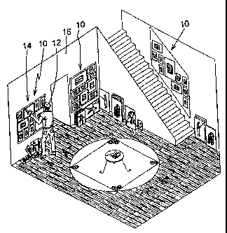
Turning to FIG. 1, shown therein is an illustrative view of the present
invention 10 in use. Shown is the present invention 10 being a picture
positioning
template used to provide and indicate to the user 12 where the optimum
placement
of a fastener used for the attachment of a display 14 or photograph should be
placed for an ideal aesthetic arrangement. The template 10 additionally has a
plurality of individual and segregated indicia which correlate to define to an
individual user 12 when the present invention is placed at the proper
elevation and
being properly vertically and horizontally squared upon a vertical 16 planar
or
curved surface wherein a shearable adhesive may be used to maintain the
present
invention in the selected position.
Turning to FIG. 2, shown therein is a front view of the present invention 10.
Shown is the present invention 10 being a reusable sheet of planar pliable
material
18 having a plurality of fastener placement markers 20 used to indicate the
point
where a fastener should be used along with having relative axial indicia
inscribed to
enable the user to coordinate what markers to use relative to the present
inventions
rotational placement. Also shown are axial correlation guides 22, bubble level
placement indicia 24, representative frame indicia 26, eye level guides 28,
and
peripheral guides 32.
CA 02537845 2006-02-28
13
Turning to FIG. 3, shown therein is a detailed front view of the frame indicia
26 of the present invention. Shown is the present invention having frame
indicia 26
representative of the placement of a predetermined frame size; e.g., 10
inchx12
inch, inscribed thereon. Provided within the inner perimeter of the frame
indicia 26
are fastener placement markers 20 with respective axial indicia or axial
correlation
guides 22 to express correct fastener (i.e., nail hole) placement for the
related frame
size. Also shown is planar pliable material 18. The present invention has a
plurality
of variously common-sized frame indicia 26 thereon wherein the indicia 26 are
arranged in different configurations with the edges of the indicia 26 being
parallel
and symmetrically arranged with each other and all indicia.
Turning to FIG. 4, shown therein a detailed front view of the eye level guide
28 of the present invention. Shown is the present invention having indicia
representative of the elevation at which the present invention should and/or
could
be placed upon a vertical surface with respect to the viewer for correct
picture group
height being a centrally disposed eye level guide 34 and a horizontal eye
level
guide line 36.
Turning to FIG. 5, shown therein is a detailed view of the level placement of
the present invention. Shown is the bubble level placement indicia 24 of the
present
invention having an area marked where a bubble leveler should be adhered to
allow
the user to horizontally and vertically square the present invention against a
vertical
surface. Also shown is the axial correlation guide or indicia 22.
Turning to FIG. 6, shown therein is a perspective view of the present
invention 10. Shown is the present invention 10 adhered to a vertical surface
16
such as a wall, by means of a non-shear, removable and adjustable adhesive 38
in
the form of putty. Additionally shown is the placement of the bubble leveler
40 onto
the level placement indicia 24, with the bubble leveler having a non-shear
adhesive
backing 38 for attachment to the level placement indicia 24.
CA 02537845 2006-02-28
14
Turning to FIG. 7, shown therein is a front view of a plurality of the present
invention 10. Shown are multiple templates 10 overlapping at their ends or
edges
42 and aligning by using the peripheral guide markers 32 as indicated. The
templates 10 are arranged in a formation to show the infinite combinations
that may
be used. These combinations allow the present invention 10 to cover any size
wall
and also offer a greater atheistic appearance, function and coverage for the
user.
Turning to FIG. 8, shown therein is a front view of an additional element of
the present invention 10. Shown is an additional element of the present
invention 10
that would enable the user to apply the invention on a non-horizontal or
angled wall
line such as a staircase wall. Shown are previously disclosed elements 18, 20,
24,
26, 28, 32 along with cutting guide 44 which allows the user to diagonally cut
the
sheets into usably sized portions.
Turning to FIG. 9, shown therein is a plurality of the additional element of
the
present invention 10. Shown are three elements of the present invention 10 one
overlapping at 46 and aligning to the other by using the peripheral guides 32.
Angled templates can also be used in conjunction with rectangular instances of
the
present invention for staircases 48, landings 50 and hallways. The arrangement
of
multiple elements also offers a greater atheistic appearance, function and
coverage
for the user.
Turning to FIG. 10, shown therein is a plurality of the additional element of
the present invention 10. Shown is a plurality of the present invention 10
that would
enable the user to apply the invention on a large staircase wall. The template
element 52 has been trimmed off using the cutting guide 44. Template element
52
can now overlap and align with template element 54 by using the peripheral
guide
markers 32 available on both elements 52, 54.
CA 02537845 2006-02-28
Turning to FIG. 11, shown therein is an additional element of the present
invention 10. Shown is the present invention 10 trimmed by scissors at 56
which
would enable the user to use part of the present invention on a small wall and
still
have the guides 32 available for accurate and level placement of the picture
frames.
5 This ability to be separated also allows users to change configuration by
combining
sections of a template 10 in different ways without loosing accuracy/function
of
template.
Turning to FIG. 12, shown therein is an additional element of the present
10 invention 10. Shown is an additional element of the present invention 10
wherein by
cutting along the outside of the frame at 58 and removing the frame 60 from
the
template 10 creates an individual frame template 60. The individual templates
60
retain their indicia and when bonded to a wall using tape or the like 62
allows the
user to hang individual picture frames. Other previously disclosed elements
20, 22
15 and 43 are also shown.
Turning to FIG. 13, shown therein is an additional element of the present
invention 10. Shown is the present invention 10 that would enable the user to
apply
the invention on a concave, curved wall 64.
Turning to FIG. 14, shown therein is an additional element of the present
invention 10. Shown is the present invention that would enable the user to
apply the
invention on a convex, curved wall 66.
Turning to FIG. 15, shown therein is an additional element of the present
invention 10. Shown is the present invention 10 that would enable the user to
apply
the invention in a corner 68 of a wall.
Turning to FIG. 16, shown therein is an additional element of the present
invention 10. Shown is the present invention 10 with 3D object viewing boxes
70
CA 02537845 2006-02-28
16
thereon. This shows that the user will be able to hang shadow boxes 70 in a
level
formation on a vertical surface 16 with accuracy.
Turning to FIG. 17, shown therein is an additional element of the present
invention 10. Shown is the present invention with a plasma television 72
thereon.
This shows that the user will be able to hang thin screen televisions 72 in a
level
formation on a vertical surface 16 with accuracy.
Turning to FIG. 18, shown therein is an additional element of the present
invention 10. Shown is the present invention 10 being a reusable sheet of
planar
pliable material 18 having a plurality of fastener placement markers 20 used
to
indicate the point where fasteners should be used. The template 10 is for
hanging
shelves level in a specific predetermined order. Shown are the representative
shelf
indicia 74, peripheral guides 32, axial correlation guide 22, eye level guides
28,
bubble level placement indicia 24 and fastener placement indicia 20.
Turning to FIG. 19, shown therein is an additional element of the present
invention 10. Shown are shelves 76 mounted using the shelf template element of
the present invention. Shown are picture frame 14, door 76, shelf 77, wall 16,
window 78, displayed object 80, shelf supporting element 82, and fastener 84
placement.
The present invention is used to mark where the hooks to hang the frames
should be placed. Once the area is marked, the template is removed, the hooks
are
applied to the wall surface and then the frames are put in place. At no time
during or
after this process are template and frames seen together on the wall. We have
however shown them together in some cases for purpose of illustration.