Note : Les descriptions sont présentées dans la langue officielle dans laquelle elles ont été soumises.
CA 02537915 2006-02-28
#387245
AIR VENT INSERTS
TECHNICAL FIELD
The present invention is generally related to air movers and air purifiers,
and more particularly, but not exclusively, is related to indoor air movers
and
purifiers that can be unobtrusively mounted in an air duct opening. For
example,
certain embodiments of the present invention can be considered improvements to
the device depicted in U.S. Patent No. 5,632,677.
1o BACKGROUND
Indoor air quality is a matter of growing concern, and a variety of air
movers and/or air purification devices have been developed. For example, air
purification units, including static electricity filters, ozone generators, UV
generators, and negative ion generators, clean and sanitize the air by
collecting
15 dust, killing airborne molds and bacteria, or otherwise reducing the level
of
airborne pollutants. Fans and blowers can be used alone or in combination with
these air purification units to circulate air in a single room or to move air
through a
HVAC system. However, while the basic operation of these types of devices is
well known, there is still room for improvement, particularly with respect to
ease
20 of installation, ease of integration with other devices or into a whole
house system,
energy efficiency, safety, and cost effectiveness.
For example, many commercially available stand alone units are bulky,
inefficient and not easily and/or unobtrusively integrated into a room. These
units
traditionally run on AC power, and existing furniture, traffic patterns and
aesthetic
25 constraints often dictate where these stand alone units may be located in a
room.
Other types of units are designed to be substantially permanently mounted
inside
the ductwork or directly to a central furnace or air conditioner. While such
mounting avoids the concerns with being located in the living space,
retrofitting
these devices into existing systems can be a challenge, since modifications to
the
3o existing ductwork and electrical wiring are often required. Furthermore for
both
stand alone units and permanently installed devices, finding the proper
settings and
making appropriate adjustments for changing conditions can be a challenge.
CA 02537915 2006-02-28
2
Accordingly, there is a need for improved air movers and purification devices
that
are easy to install and/or which can be easily retrofit into existing HVAC
systems.
The present invention addresses these needs and does so in an efficient and
cost
effective manner.
CA 02537915 2006-02-28
3
BRIEF DESCRIPTION OF THE FIGURES
Although the characteristic features of this invention will be particularly
pointed out in the claims, the invention itself, and the manner in which it
may be
made and used, may be better understood by referring to the following
description
taken in connection with the accompanying figures forming a part thereof.
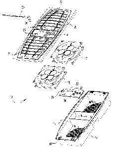
FIG. 1 is an exploded view of a vent fan according to a first embodiment.
FIG. 2 is a perspective view of the FIG. 1 vent fan.
FIG. 3 is a side sectional view of a vent fan with integrated air purifier as
installed in an air vent opening.
FIG. 4 is a perspective view of the FIG. 1 vent fan replacing a floor vent in
a room and in wireless communication with a wall mounted thermostat.
FIG. 5 is a cutaway view of the underside of a UV air purifier according to
another embodiment.
CA 02537915 2006-02-28
4
SUMMARY
In one form, the present invention provides an air vent insert for boosting
circulation and/or purifying the air in the room in a safe and cost effective
manner.
The insert includes a housing configured to be inserted into an air duct and
covered
by a face plate. The housing has a flange portion that rests on the wall or
floor
surrounding the duct opening and a body portion recessed in the duct to
achieve a
low profile design. The body portion contains one or more fans and/or air
purification units coupled to an electronic control unit. For increased
safety, the
entire unit operates on low voltage DC power supplied from an AC/DC converter
plugged into a standard 3 prong wall outlet.
CA 02537915 2006-02-28
DESCRIPTION OF THE ILLUSTRATED EMBODIMENTS
For the purposes of promoting an understanding of the principles of the
invention, reference will now be made to the embodiments illustrated in the
drawings and specific language will be used to describe the same. It will
5 nevertheless be understood that no limitation of the scope of the invention
is
hereby intended. Alterations and further modifications in the illustrated
devices,
and such further applications of the principles of the invention as
illustrated herein
are contemplated as would normally occur to one skilled in the art to which
the
invention relates.
In one form, the present invention provides a vent fan for placement in an
air duct. Refernng to FIGS. 1 and 2, a vent fan according to an embodiment
includes a pair of fans 17 and 18 mounted in a housing 12. Housing 12 has a
body
portion 14 and a flange portion 16. Body portion 14 is sized to fit into an
air duct,
and as illustrated is generally rectangular in shape so as to fit into a
standard
rectangular air duct opening. Flange portion 16 extends around the periphery
of
the top of the body portion 14 to create a lip that can rest on the wall or
floor
surrounding the air duct opening while body portion 14 extends into the duct.
An electronic control unit 30 is mounted in housing 12 between fans 17, 18
and serves to control the operation of the fans. A face plate 20 mounts to the
2o housing and has a pair of grills 21, 22 that cover fans 17 and 18
respectively. A
control panel 23 is located between grills 21, 22 and includes a series of
buttons 24
that are aligned with corresponding contact pads 34 on control unit 30.
Indicator
lights 32 are provided on control unit 30 and are configured to shine through
corresponding windows 26 in control panel 23.
In the illustrated embodiment, air vent 10 is configured for safe, low
voltage operation. The electrical power for vent 10 is preferably in the form
of a
direct current (DC). The DC power is supplied via an AC/DC converter 95 (FIG.
4) that plugs into a standard 3 prong electrical outlet and converts AC power
from
the wall outlet into 12V DC power to vent 10. The male end of the adapter cord
29
connects to power socket 36 on control unit 30 through an opening in face
plate 20,
and a channel 28 is provided in face plate 20 to accommodate the power cord.
As
CA 02537915 2006-02-28
6
shown in FIG. 2, this allows the power cord to be substantially flush with the
top
face of face plate 20 and out of the way when vent 10 is in use.
The use of low voltage DC power is advantageous for a variety of reasons.
Low voltage and low current operation consumes less power and is more energy
efficient than AC operation. Less costly components can be used, and the lower
risk of electrical shock qualifies the device for a less rigorous UL
certification
procedure. The increased safety from low voltage operation is particularly
important for floor mounted units such as shown in FIG. 4, and/or where small
children or pets are around, since it reduces the risks of serious accidents
or injuries
1o due to spilled liquids or foreign objects falling into the device.
In other embodiments, other sources of power may be employed, such as
24V A/C or 115 V A/C. In one contemplated embodiment, device 10 is modified
to operate on battery power, for example rechargeable batteries. In still
other
embodiments, device 10 may be hardwired to existing electrical systems. For
example, in one embodiment, the device 10 is wired to and receives power (e.g.
24V A/C) directly from the central furnace or air conditioner or other central
HVAC component.
Vent fan 10 can be assembled from existing components and low cost
materials. Housing 12 is preferable designed as unitary plastic, for example
2o constructed via a die cast or molding process. Appropriate projections and
retaining clips can be integrally formed with the housing to allow fans 17, 18
and
control unit 30 to be snap fit in place. Control unit 30 can be constructed
from
printed circuit board with appropriate electronic components, such as a
microprocessor and associated memory, for carrying out the control functions
described more fully below. Fans 17, 18 can be single speed or multiple
speeds.
Preferably, the fans are variable speed fans or are continuously variable with
the
fan speed set by controller 30. To promote quite operation and reduce wear on
the
fans, the controller can be configured to gradually ramp up fans speed and/or
provide power in a cycle or hysteresis.
It is to be appreciated that in use, vent fan 10 would be mounted in an air
duct as a replacement to existing face plates. With the fans blowing into the
room,
vent fan 10 serves to boost the flow of conditioned air from the central
furnace or
CA 02537915 2006-02-28
7
air conditioner (not shown) into the room. Control unit 30 is preferably
programmed to have different operation modes, and the fan speed is
programmable
or selectable based on the size of the room. Optionally, one or more
temperature
sensors are connected to control unit 30 to sense the temperature of the air
in the air
duct and/or in the room, and control unit 30 controls operations of the fans
based
on signals from these temperature sensor(s). Suitable temperature sensors
include
thermistors, thermocouples or bi-metal strips. A user can select the desired
operational mode via buttons 24, and the power status and operational mode can
be
indicated via lights 32.
1o Alternatively or in addition, device 10 can be adapted to receive control
signals remotely. In this variation, a wireless receiver, such as one that
receives IR,
RF or blue tooth signals, is connected to control unit 30. Where line of sight
is
important (such as with IR transmitters) a receiver can be located on face
plate 20
and hardwired to control unit 30. In this way, device 10 can receive control
signals
or other inputs from a handheld device, a wall mounted remote control and/or a
central furnace or air conditioner without the need to run additional wires.
For example, FIG. 4 illustrates one such implementation where wireless
electromagnetic signals 98, 99 are used to establish communication between a
floor
mounted air vent and a wall mounted thermostat 97. A transmitter (not shown)
in
2o the thermostat 97 sends information such as the measured temperature, a
setpoint,
and/or the operational status of the furnace or air conditioner to the
receiver (not
shown) in the vent fan 10. Control unit 30 would then process this
information, for
example comparing the temperature measured at the vent with the temperature
received from the thermostat, and take appropriate corrective action, such as
by
activating fans 17, 18. In still another variation, a motion sensor can be
used, for
example to power on the device or change it operational mode when someone
enters the room. The motion sensor can be mounted on the face plate 20 or it
may
be freestanding and connected wirelessly to the control unit.
Embodiment are also contemplated where the face plate 20 is devoid of all
3o controls. Such a device can rely solely on remote control (such as RF) or
the
appropriate control buttons can be concealed under the face plate 20, for
example
under flange portion 16 or along the side of body portion 14 of housing 12.
CA 02537915 2006-02-28
Useful operational modes of devices according to the present invention
include a heating mode, a cooling mode, a continuous operation mode, and a
timed
mode. In an exemplary heating mode, control unit 30 monitors the temperature
in
the room and in the air duct. When control unit 30 senses that the temperature
in
the duct has increased relative to the temperature in the room (a condition
that
would indicate that the furnace has begun to blow heat through the ducts)
control
unit 30 starts fans 17, 18. The fans then run continuously until control unit
30
determines that the temperature in the duct has begun to decrease (indicating
that
the furnace has ended its run) at which time control unit 30 shuts off the
fans and
1o waits for the next cycle. Cooling mode operation would be similar to
heating mode
save that fans 17, 18 are operated when the temperature in the duct is
determined to
be lower than the temperature in the room. The fans can be configured to
operate
substantially continuously in continuous operation mode and for a set time
period
in the timed mode.
In addition to or in place of functioning as an air booster, vent fan 10 can
be
modified to incorporate one or more air purification devices. Refernng now to
FIG. 3, a vent device 80 is depicted mounted in a floor duct 40. Like vent fan
10
described above, flange portion 16 rests on the floor 50 surrounding the duct
opening, and face plate 20 covers the device. With body portion 14 recessed
below
floor 50, vent device 80 also has a low profile, for example, having the
distance D
between the upper surface of face plate 20 and the plane of the surrounding
floor
50 be less than about 1.5 inches.
Vent device 80 includes a temperature sensor 70 and is otherwise identical
to vent device 10 save the addition of an air purification system 90. Any of a
variety of commercially available air purification systems can be employed in
this
manner, such as those employing ozone generators, UV filters, negative ion
generators, static electricity filters, photocatalyic oxidation or
combinations
thereof. An exemplary ozone based system is illustrated in FIG. 3 and includes
a
pair of plate emitters 64 and 68 electrically connected via lines 66, 62 to a
high
voltage generator 60. As is known in the art, ozone is generated in emitters
64, 68
via a high voltage applied across spaced electrodes or conductive plates. A
variety
of suitable plate-type ozone generators are commercially available, such as
Part
CA 02537915 2006-02-28
9
No. YEK-100 from YEK, HighTech Co. Ltd., Hong Kong. Pipeline-type ozone
generators can also be employed, such as Part No. YEK-G20, also from YEK. As
illustrated in FIG. 3, purification system 90 is mounted to the underside of
housing
14. In an alternative arrangement, housing 14 can be adapted to contain some
or
all of purification system 90, e.g. so that one or more components of system
90 are
mounted inside housing 14.
As mentioned above, devices according to the present invention can include
air purifiers without fans. One such embodiment is depicted in FIG. 5, which
illustrates a vent device 100 that purifies air via a photocatalytic oxidation
process.
to Air vent device 100 has a generally rectangular housing 114 with a control
unit 134
at one end. A light source 138 extends laterally from control unit 134 and is
surrounded by a cylindrical shell of photocatalytic material 136 (such as a
titanium
oxide coated substrate). Contaminates in air passing through device 100, for
example under the power of a central blower, deposit on material 136 and are
catalytically oxidized with the energy supplied by light 138. A shield 130
prevents
light from source 138 from spilling through grill 122 in face plate 110 and
into the
room. An air vent device having a UV filter can be constructed substantially
identically as device 100 save that in UV filtration there would typically be
no need
for material 136 surrounding the light.
CA 02537915 2006-02-28
CLOSURE
While the invention has been illustrated and described in detail in the
drawings and foregoing description, the same is to be considered as
illustrative and
not restrictive in character. Only certain embodiments have been shown and
5 described, and all changes, equivalents, and modifications that come within
the
spirit of the invention described herein are desired to be protected. Further,
any
theory, mechanism of operation, proof, or finding stated herein is meant to
further
enhance understanding of the present invention and is not intended to limit
the
present invention in any way to such theory, mechanism of operation, proof, or
1o finding. Thus, the specifics of this description and the attached drawings
should
not be interpreted to limit the scope of this invention to the specifics
thereof.
Rather, the scope of this invention should be evaluated with reference to the
claims
appended hereto.
In reading the claims it is intended that when words such as "a", "an", "at
least one", and "at least a portion" are used there is no intention to limit
the claims
to only one item unless specifically stated to the contrary in the claims.
Further,
when the language "at least a portion" and/or "a portion" is used, the claims
may
include a portion and/or the entire items unless specifically stated to the
contrary.
Likewise, where the term "input" or "output" is used in connection with an
electric
2o device or flow path, it should be understood to comprehend singular or
plural and
one or more signal channels or flow paths as appropriate in the context.
Finally, all
publications, patents, and patent applications cited in this specification are
herein
incorporated by reference to the extent not inconsistent with the present
disclosure
as if each were specifically and individually indicated to be incorporated by
reference and set forth in its entirety herein.