Sélection de la langue

Search

Sommaire du brevet 2539045 

Énoncé de désistement de responsabilité concernant l'information provenant de tiers

Une partie des informations de ce site Web a été fournie par des sources externes. Le gouvernement du Canada n'assume aucune responsabilité concernant la précision, l'actualité ou la fiabilité des informations fournies par les sources externes. Les utilisateurs qui désirent employer cette information devraient consulter directement la source des informations. Le contenu fourni par les sources externes n'est pas assujetti aux exigences sur les langues officielles, la protection des renseignements personnels et l'accessibilité.

Disponibilité de l'Abrégé et des Revendications

L'apparition de différences dans le texte et l'image des Revendications et de l'Abrégé dépend du moment auquel le document est publié. Les textes des Revendications et de l'Abrégé sont affichés :

  • lorsque la demande peut être examinée par le public;
  • lorsque le brevet est émis (délivrance).
(12) Brevet: (11) CA 2539045
(54) Titre français: DISPOSITIF D'ATTACHE RAPIDE POUR OUTIL D'EXCAVATEUR
(54) Titre anglais: AN EXCAVATOR TOOL QUICK ATTACHMENT DEVICE
Statut: Accordé et délivré
Données bibliographiques
(51) Classification internationale des brevets (CIB):
  • E02F 03/36 (2006.01)
(72) Inventeurs :
  • MCCORMICK, PATRICK (Irlande)
  • MCCORMICK, CAROLINE (Irlande)
  • SEGARTY, MARTIN (Irlande)
  • EGENTON, WILLIAM (Irlande)
(73) Titulaires :
  • PATRICK MCCORMICK
  • CAROLINE MCCORMICK
  • MARTIN SEGARTY
  • WILLIAM EGENTON
(71) Demandeurs :
  • PATRICK MCCORMICK (Irlande)
  • CAROLINE MCCORMICK (Irlande)
  • MARTIN SEGARTY (Irlande)
  • WILLIAM EGENTON (Irlande)
(74) Agent: RICHES, MCKENZIE & HERBERT LLP
(74) Co-agent:
(45) Délivré: 2013-03-12
(86) Date de dépôt PCT: 2004-09-20
(87) Mise à la disponibilité du public: 2005-03-24
Requête d'examen: 2009-09-11
Licence disponible: S.O.
Cédé au domaine public: S.O.
(25) Langue des documents déposés: Anglais

Traité de coopération en matière de brevets (PCT): Oui
(86) Numéro de la demande PCT: PCT/IE2004/000128
(87) Numéro de publication internationale PCT: IE2004000128
(85) Entrée nationale: 2006-03-14

(30) Données de priorité de la demande:
Numéro de la demande Pays / territoire Date
S2003/0685 (Irlande) 2003-09-18
S2004/0194 (Irlande) 2004-03-26

Abrégés

Abrégé français

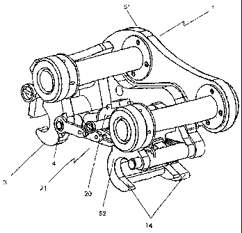
L'invention concerne un dispositif d'attache rapide (1) servant à attacher un outil à un bras plongeur (2) d'un excavateur. Ce dispositif comprend un élément structural (52) comportant deux systèmes de réception (12, 14) pour des tiges (11, 15) d'outil. Le système de réception (12) comprend un élément de verrouillage (3) amovible actionné par un vérin hydraulique (20) pour bloquer et débloquer la tige (11) et le système de réception (14) comprend un élément de blocage (22) amovible à ressort pour bloquer et débloquer la tige (15). Un ensemble de commande (21) est relié entre l'élément de verrouillage (3) et l'élément de blocage (22), cet ensemble servant uniquement à débloquer l'élément de blocage (22) lorsque le dispositif d'attache rapide (1) est inversé par rapport à une position normale de travail et que le vérin hydraulique (20) est activé.


Abrégé anglais


Excavator tool quick attachment device (1) is used to attach a tool to a
dipper arm (2) of an excavator. Body member (52) has two receivers (12,14) for
tool pins (11,15). Receiver (12) has a movable latch (3) powered by an
hydraulic ram (20) for securing and releasing pin (11) and receiver (14) has a
movable spring loaded lock (22) for securing and releasing pin (15). A control
assembly (21) is connected between latch (3) and lock (22) but only operates
to release lock (22) when the device (1) is inverted relative to a normal
working position and the hydraulic ram (20) is activated.

Revendications

Note : Les revendications sont présentées dans la langue officielle dans laquelle elles ont été soumises.


8
CLAIMS:
1. An excavator tool quick attachment device for attaching a tool to a dipper
arm of an excavator, the device comprising a body member with an engaging
means at or about each end for engagement with two connecting pins disposed
on a tool, the first engaging means being a movable engaging means, the device
further comprising a drive means mounted between the body member and the
movable engaging means for moving the movable engaging means between a
tool pin engaging position and a tool pin releasing position, the second
engaging
means being a second movable engaging means normally biased into a tool pin
engaging position by a biasing means, a control means mounted between the
first movable engaging means and the second movable engaging means,
wherein the control means is selected to act on the second movable engaging
means to overcome the biasing force only when the quick attachment device is
inverted relative to a normal working position and the drive means is
actuated,
whereby the tool can not be released when it is in a normal working position
in
the event the drive means fails or is inadvertently actuated by an operator.
2. An excavator tool quick attachment device as claimed in Claim 1, in which
the control means comprises an adjustable length actuating assembly having a
catch means to fix the length of the actuating assembly at a predetermined
position when the quick attachment device is inverted relative to the normal
working position and the drive means is actuated.
3. An excavator tool quick attachment device as claimed in Claim 2, in which
the actuating assembly is pivotally connected to both the first and second
movable engaging means.
4. An excavator tool quick attachment device as claimed in Claim 2 or 3, in
which the actuating assembly is in two parts, the first part having a slot
extending along
a substantial portion of its longitudinal axis and the second part having two
pins spaced
apart along its length and extending laterally therefrom, the pins being
formed for

9
slidable engagement with the slot of the first part, allowing relative
movement between
the two parts, the pins movably holding the two parts together.
5. An excavator tool quick attachment device as claimed in Claim 4, in which
the catch means is provided by a notch on the slot which is located above the
pins in any normal working position of the tool and the slot is located below
the
pins only when the quick attachment device is inverted relative to the normal
working position, whereby when the quick attachment device is inverted and the
drive means is actuated to move the first movable engaging means from the tool
pin engaging position to the tool pin releasing position, the pins of the
second
part of the actuator assembly slide along the slot until the leading pin
encounters
the notch into which it drops under the force of gravity thereby fixing the
length of
the actuating assembly after which point continued stroke action of the drive
means causes the actuating assembly to move the second movable engaging
means away from the tool pin engaging position thereby releasing.
6. An excavator tool quick attachment device as claimed in any one of claims 1
to 5,
in which the first movable engaging means is provided by a pair of latch hooks
pivotally
mounted on the body and in which the second movable engaging means is provided
by
a lock pivotally mounted on the body.
7. An excavator tool quick attachment device as claimed in any one of claims 1
to 6,
in which the drive means is a double acting piston and cylinder unit.
8. An excavator tool quick attachment device as claimed in any one of claims 1
to 7
including a tilt mechanism by means of which the device can be tilted about a
longitudinal pivotal axis.
9. An excavator tool quick attachment device (1, 101) for attaching a tool to
a dipper
arm (2) of an excavator, the device comprising a body member (52) with first
and second
engaging means (3, 12, 14, 22) at or about each end for engagement with two
connecting pins (11, 15) disposed on the tool, the first engaging means (3,
12) being a
movable engaging means (3), the device further comprising a drive means (20)
mounted

10
between the body member (52) and the first movable engaging means (3) for
moving the
first movable engaging means (3) between a tool pin engaging position and a
tool pin
releasing position, the second engaging means (14, 22) being a second movable
engaging means (22) normally biased into a tool pin engaging position by a
biasing
means, a control means (21, 121) mounted between the first movable engaging
means
(3) and the second movable engaging means (22), wherein the control means (21,
121)
acts on the Second movable engaging means (22) to overcome the biasing force
characterised in that the control means (21, 121) is selected to act between
the first and
second movable engaging means (3, 22) only when the quick attachment device
(1,
101) is inverted relative to a normal working position and the drive means
(20) is
actuated, whereby the tool can not be released when it is in the normal
working position
in the event the drive means (20) fails or is inadvertently actuated by an
operator.
10. An excavator tool quick attachment device as claimed in Claim 9, in which
the
control means (21) comprises an adjustable length actuating assembly (23)
having a
catch means (24, 25, 28, 29, 32) to fix the length of the actuating assembly
at a
predetermined position when the quick attachment device is inverted relative
to the
normal working position and the drive means is actuated.
11. An excavator tool quick attachment device as claimed in Claim 10, in which
the
actuating assembly (23) is pivotally connected to both the first and second
movable
engaging means (3, 22).
12. An excavator tool quick attachment device as claimed in Claim 10 or 11, in
which
the actuating assembly (23) is in two parts (24, 25), the first part (24)
having a slot (28)
extending along a substantial portion of its longitudinal axis and the second
part (25)
having two pins (29) spaced apart along its length and extending laterally
therefrom, the
pins (29) being formed for slidable engagement with the slot (28) of the first
part (24),
allowing relative movement between the two parts (24, 25), the pins (29)
movably
holding the two parts (24, 25) together.
13. An excavator tool quick attachment device as claimed in Claim 12, in which
the
catch means is provided by a notch (32) on the slot (28) which is located
above the pins
(29) in any normal working position of the tool and the notch (32) is located
below the

11
pins (29) only when the quick attachment device is inverted relative to the
normal
working position, whereby when the quick attachment device is inverted and the
drive
means (20) is actuated to move the first movable engaging means (3) from the
tool pin
engaging position to the tool pin releasing position, the pins (29) of the
second part (25)
of the actuator assembly (23) slide along the slot (28) until the leading pin
encounters
the notch (32) into which it drops under the force of gravity thereby fixing
the length of
the actuating assembly (23) after which point continued stroke action of the
drive means
(20) causes the actuating assembly to move the second movable engaging means
(22)
away from the tool pin engaging position thereby releasing said leading pin.
14. An excavator tool quick attachment device as claimed in any one of claims
9 to
13, in which the first movable engaging means is provided by a pair of latch
hooks (3)
pivotally mounted on the body and in which the second movable engaging means
is
provided by a lock (22) pivotally mounted on the body.
15. An excavator tool quick attachment device as claimed in any one of claims
9 to
14, in which the drive means is a double acting piston (20) and cylinder unit.
16. An excavator tool quick attachment device as claimed in any one of claims
9 to
15 including a tilt mechanism by means of which the device can be tilted about
a
longitudinal pivotal axis.

Description

Note : Les descriptions sont présentées dans la langue officielle dans laquelle elles ont été soumises.


CA 02539045 2011-07-28
1
AN EXCAVATOR TOOL QUICK ATTACHMENT DEVICE
Field of the Invention
The present invention relates to an excavator tool quick attachment device and
more
particularly to a safety mechanism for an excavator tool quick attachment
device.
Background of the Invention
Pneumatic/hydraulic latches on quick attachment devices are well known and are
generally
mounted on a tool engaging portion which has two hooks, one of which is on
each end of
the device. The excavator operator locates one of the hooks around the first
pin of the tool
and raises a dipper arm of the excavator. The rams of the dipper arm are
manipulated until
the second hook is located adjacent the second pin of the tool and a
pneumatic/hydraulic
latch comprising a hydraulic/pneumatic piston connected between the attachment
device
and the latch is actuated to lock the second pin of the tool onto the quick
attachment
device.
The problem with this latch is that failure of the hydraulic/pneumatic
cylinder could result in
the latch opening and allowing the tool such as a bucket to become separated
from the
quick attachment device with potentially disastrous consequences for anyone in
the vicinity.
A number of safety pins and other safety mechanisms have been developed but
most of
these require to be inserted manually. Further secondary safety systems
utilising hydraulic
systems have also been developed which add extra system maintenance and
expense.
Summary of the Invention
It is an object of the present invention to overcome the need for manually
operable safety
pins or complex hydraulic systems, both of which are used to prevent
unintended release of
the tool from the quick attachment device.
Accordingly, the present invention provides an excavator tool quick attachment
device for
attaching a tool to a dipper arm of an excavator, the device comprising a body
member with

CA 02539045 2011-07-28
2
an engaging means at or about each end for engagement with two connecting pins
disposed on the tool, the first engaging means being a movable engaging means,
the
device further comprising a drive means mounted between the body member and
the
movable engaging means for moving the movable engaging means between a tool
pin
engaging position and a tool pin releasing position, the second engaging means
being a
second movable engaging means normally biased into a tool pin engaging
position by a
biasing means, a control means mounted between the first movable engaging
means and
the second movable engaging means, wherein the control means acts on the
second
movable engaging means to overcome the biasing force only when the quick
attachment
device is inverted relative to a normal working position and the drive means
is actuated,
whereby the tool can not be released when it is in the normal working position
in the event
the drive means fails or is inadvertently actuated by an operator.
In another aspect, the present invention resides in an excavator tool quick
attachment
device for attaching a tool to a dipper arm of an excavator, the device
comprising a body
member with first and second engaging means at or about each end for
engagement with
two connecting pins disposed on the tool, the first engaging means being a
movable
engaging means, the device further comprising a drive means mounted between
the body
member and the first movable engaging means for moving the first movable
engaging
means between a tool pin engaging position and a tool pin releasing position,
the second
engaging means being a second movable engaging means normally biased into a
tool pin
engaging position by a biasing means, a control means mounted between the
first movable
engaging means and the second movable engaging means, wherein the control
means
acts on the Second movable engaging means to overcome the biasing force
characterised
in that the control means acts between the first and second movable engaging
means only
when the quick attachment device is inverted relative to a normal working
position and the
drive means is actuated, whereby the tool can not be released when it is in
the normal
working position in the event the drive means fails or is inadvertently
actuated by an
operator.
The quick attachment device being in an inverted position is commonly referred
to in the art
as the crouched or valueless position.

CA 02539045 2011-07-28
3
Preferably, the control means comprises an adjustable length actuating
assembly having a
catch means to fix the length of the actuating assembly at a predetermined
position when
the quick attachment device is inverted relative to a normal working position
and the drive
means is actuated. Advantageously, the use of mechanical components powered by
an
already present drive means reduces the complexity and cost of a secondary
safety
mechanism.
Ideally, the actuating assembly is pivotally connected to both movable
engaging means.
Preferably, the actuating assembly is in two parts, the first part having a
slot extending
along a substantial portion of its longitudinal axis and the second part
having two pins
spaced apart along its length and extending laterally therefrom, the pins
being formed for
slidable engagement with the slot of the first part, allowing relative
movement between the
two parts, the pins movably holding the two parts together.
Ideally, the catch means is provided by a notch on the slot which is located
above the pins
in any normal working position of the tool and the slot is located below the
pins only when
the quick attachment device is inverted relative to the normal working
position.
Preferably, when the quick attachment device is inverted and the drive means
is actuated to
move the first movable engaging means from a tool pin engaging position to a
tool pin
releasing position, the pins of the second part of the actuator assembly slide
along the slot
until the leading pin encounters the notch into which it drops under the force
of gravity
thereby fixing the length of the actuating assembly after which point
continued stroke action
of the drive means causes the actuating assembly to move the second movable
engaging
means away from the tool pin engaging position thereby releasing that tool
pin.
Ideally, the first movable engaging means is provided by a pair of latch hooks
pivotally
mounted on the body.
Preferably, the second movable engaging means is provided by a lock pivotally
mounted on
the body.

CA 02539045 2011-07-28
3a
Ideally, the drive means is a double acting piston and cylinder unit.
Advantageously, the excavation tool quick attachment device includes a tilt
mechanism by
means of which the device can be titled about a longitudinal pivotal axis.
Brief Description of the Drawings
This invention will now be described with reference to the accompanying
drawings which
show, by way of example only, two embodiments of an excavator tool quick
attachment
device in accordance with the invention.

CA 02539045 2006-03-14
WO 2005/026454 PCT/IE2004/000128
4
In the drawings:-
Fig. 1 is a perspective view of a first embodiment of a quick attachment
device;
Fig. 1 a is a side view of the first embodiment of a quick attachment device
mounted on a dipper arm of an excavator in a normal working position;
Fig. 2 is a second side view of the quick attachment device with a latch in
an open position;
Fig. 3 is a side view of the quick attachment device in an inverted position;
Fig. 4 is a second side view of the quick attachment device in an inverted
position showing the safety mechanism in an open position;
Fig. 5 is a detail view taken from the opposite side as the views of Figs. I
to
4 of the safety mechanism in a normal working position;
Fig. 6 is a second detail view of the safety mechanism of Fig. 5 in a second
working position;
Fig. 7 is a third detail view of the safety mechanism of Fig. 5 and Fig. 6 in
an uncoupling position;
Fig. 8 is a fourth detail view of the safety mechanism in an uncoupled
position;
Fig. 9 is a plan view of a second embodiment of a quick attachment device
according to the invention incorporating a tilting mechanism;
Fig. 10 is a first end view of the second embodiment;

CA 02539045 2011-07-28
Fig. 11 is a side view of the second embodiment;
Fig. 12 is a second end view of the second embodiment;
Fig. 13 is a perspective view of the second embodiment showing the mechanism
tilted 45
degrees in one direction;
Fig. 14 is a further perspective view of the second embodiment showing the
mechanism
tilted 45 degrees in the opposite direction;
Fig. 15 is a lower perspective view of the second embodiment showing the
mechanism in a
non-tilted position; and
Fig. 16 is an upper perspective view of the second embodiment with the
mechanism in the
non-tilted position.
Detailed Description of the Preferred Embodiments
Referring to the drawings, Figs. 1 to 4 show an excavator tool quick
attachment device 1
mounted on an excavator dipper arm 2 and Figs. 5 to 8 show detail views of the
safety
mechanism 21 mounted on the quick attachment device 1. The quick attachment
device 1
is of the type having a dipper arm engaging portion 51 and a body portion 52
having
receivers or mouths 12,14 for receiving tool pins 11,15 respectively. The
device 1 also has
two latch plates 3 (one shown) spaced apart and being pivotally connected to
the body
portion 52 of the attachment device 1 by pivot pin 6. A hydraulic ram 20 is
connected
between heels 4 of the latch plates 3 and shaft 5. Actuation of the ram 20
causes the latch
plates 3 to pivot about pin 6 locking or releasing tool pin 11 between a
concave potion of
the latch plates 3 and a concave portion of mouth 12 of the attachment device
1. The
attachment device 1 has a second mouth 14 for engaging the other tool pin 15
at the
opposite end of the device 1. A safety mechanism indicated generally by the
reference
numeral 21 (see Figs. 5 to 8 in particular) is shown having a lock 22
pivotally mounted
adjacent the mouth 14 and a two-part actuating assembly 23. A first part 24 of
the

CA 02539045 2006-03-14
WO 2005/026454 PCT/IE2004/000128
6
actuating assembly 23 is pivotally connected to the lock 22 and the second
part 25
of the actuating assembly 23 is pivotally connected to latch plate 3. The
first part
24 of the actuating assembly 23 has a slot 28 extending along a substantial
portion of its length. The second part 25 has two pins 29 extending
transversely
therefrom and movably connecting the first and second parts 24, 25 together
with
the pins 29 being formed for slidable movement along the slot 28 in response
to
actuation of the hydraulic ram 20 to pivot the latch plates 3. The slot 28 has
a
notch 32 above the pins 29 in a normal working position and below the pins 29
in
the inverted position.
In use and referring to Fig. 1 and Fig. 5, the latch plates 3 are pivoted into
a pin 11
engaging position and lock 22 is biased into a pin 15 engaging position by a
biasing element, such as a spring (not shown). In Fig. 2 and Fig. 6, the latch
plates 3 are pivoted into a tool pin 11 releasing position by the ram. This
could be
an intentional actuation or it could have come about as a result of ram
failure or
inadvertent actuation by an operator. Due to the forces of gravity acting on
the
free end of the second part 25 and the free end of the first part 24 of the
actuating
assembly 23 the pin 29 adjacent the free end of the second part 25 slides past
the
notch 32. The complete rotation of the latch plates 3 causes the pin 29
adjacent
the free end of second part 25 to slide to an area just before the end of the
slot 28.
No force is exerted on the lock 22 by the actuating assembly 23 therefore the
lock
22 prevents the second tool pin 15 from becoming released unintentionally when
the quick attachment device 1 is in a normal working position.
In Fig. 3 and Fig. 7, the dipper arm 2 of the excavator has been pulled in
towards
the excavator and the hydraulic rams 41 of the dipper arm 2 have been
activated
so that the longitudinal axis of the quick attachment device I has been
rotated
clockwise through 180 into the inverted position compared to Figs. I and 2.
The
hydraulic ram (not shown) is activated and the pins 29 slide along the slot
28.
However, due to the rotation of the attachment device 1, the notch 32 is now
located below the pins 29. The first pin 29 adjacent the free end of the
second

CA 02539045 2006-03-14
WO 2005/026454 PCT/IE2004/000128
7
part 25 drops down into the notch 32 again due to gravitational force and
abuts
against the notch 32. At this point, the lock 22 is still engaging the tool
pin 15.
In Fig. 4 and Fig. 8, the hydraulic ram for operating the latch plates 3 has
continued with its stroke forcing pin 29 to push first part 24 of the
actuating
assembly 23 against the lock 22 overcoming the biasing force of the spring.
Lock
22 pivots about pin 42 and engaging bar 43 rotates away from mouth 14 of the
attachment device 1. Both pins 11, 15 are no longer locked in the mouths 12,
14
and movement of the dipper arm 2 allows the tool to drop onto the ground.
Referring now to the second embodiment which is shown in Figs. 9 to 15, the
excavator tool quick attachment device 101 is provided with a safety mechanism
121 which is similar in construction and operation as the safety mechanism 21
of
the first embodiment.
The excavator tool quick attachment device 101 additionally includes a tilt
mechanism 150 by means of which the device can be tilted in two directions by
approximately 45 degrees in each direction. The tilt mechanism 150 comprises
two hydraulically operated cylinders 151 and 152 which can tilt the device
about
longitudinal central pivot 155.
With the device 101 fitted to an excavator it can be used for more versatile
operations, for example, grading and digging work at an angle such as in
ditches,
dykes an drains. The operator can manoeuvre a tool around obstacles more
readily within the device 101.
It will of course be understood that the invention is not limited to the
specific details
herein described, which are given by way of example only, and that various
modifications and alterations are possible with the scope of the invention.

Dessin représentatif
Une figure unique qui représente un dessin illustrant l'invention.
États administratifs

2024-08-01 : Dans le cadre de la transition vers les Brevets de nouvelle génération (BNG), la base de données sur les brevets canadiens (BDBC) contient désormais un Historique d'événement plus détaillé, qui reproduit le Journal des événements de notre nouvelle solution interne.

Veuillez noter que les événements débutant par « Inactive : » se réfèrent à des événements qui ne sont plus utilisés dans notre nouvelle solution interne.

Pour une meilleure compréhension de l'état de la demande ou brevet qui figure sur cette page, la rubrique Mise en garde , et les descriptions de Brevet , Historique d'événement , Taxes périodiques et Historique des paiements devraient être consultées.

Historique d'événement

Description Date
Requête visant le maintien en état reçue 2023-06-21
Requête visant le maintien en état reçue 2022-09-06
Requête visant le maintien en état reçue 2021-08-20
Requête visant le maintien en état reçue 2020-09-16
Représentant commun nommé 2019-10-30
Requête visant le maintien en état reçue 2019-09-09
Requête visant le maintien en état reçue 2018-07-16
Requête visant le maintien en état reçue 2017-07-24
Requête visant le maintien en état reçue 2016-07-11
Requête visant le maintien en état reçue 2015-07-27
Requête visant le maintien en état reçue 2014-09-04
Requête visant le maintien en état reçue 2013-09-12
Accordé par délivrance 2013-03-12
Inactive : Page couverture publiée 2013-03-11
Inactive : Réponse à l'art.37 Règles - PCT 2012-12-20
Préoctroi 2012-12-20
Inactive : Taxe finale reçue 2012-12-20
Un avis d'acceptation est envoyé 2012-11-20
Lettre envoyée 2012-11-20
Inactive : Approuvée aux fins d'acceptation (AFA) 2012-11-09
Modification reçue - modification volontaire 2012-08-08
Inactive : Dem. de l'examinateur par.30(2) Règles 2012-02-09
Modification reçue - modification volontaire 2011-07-28
Inactive : Dem. de l'examinateur par.30(2) Règles 2011-01-31
Lettre envoyée 2009-10-29
Requête d'examen reçue 2009-09-11
Exigences pour une requête d'examen - jugée conforme 2009-09-11
Toutes les exigences pour l'examen - jugée conforme 2009-09-11
Inactive : Page couverture publiée 2006-05-24
Inactive : Inventeur supprimé 2006-05-16
Inactive : Notice - Entrée phase nat. - Pas de RE 2006-05-16
Inactive : Inventeur supprimé 2006-05-16
Demande reçue - PCT 2006-04-04
Exigences pour l'entrée dans la phase nationale - jugée conforme 2006-03-14
Demande publiée (accessible au public) 2005-03-24

Historique d'abandonnement

Il n'y a pas d'historique d'abandonnement

Taxes périodiques

Le dernier paiement a été reçu le 2012-09-20

Avis : Si le paiement en totalité n'a pas été reçu au plus tard à la date indiquée, une taxe supplémentaire peut être imposée, soit une des taxes suivantes :

  • taxe de rétablissement ;
  • taxe pour paiement en souffrance ; ou
  • taxe additionnelle pour le renversement d'une péremption réputée.

Les taxes sur les brevets sont ajustées au 1er janvier de chaque année. Les montants ci-dessus sont les montants actuels s'ils sont reçus au plus tard le 31 décembre de l'année en cours.
Veuillez vous référer à la page web des taxes sur les brevets de l'OPIC pour voir tous les montants actuels des taxes.

Titulaires au dossier

Les titulaires actuels et antérieures au dossier sont affichés en ordre alphabétique.

Titulaires actuels au dossier
PATRICK MCCORMICK
CAROLINE MCCORMICK
MARTIN SEGARTY
WILLIAM EGENTON
Titulaires antérieures au dossier
S.O.
Les propriétaires antérieurs qui ne figurent pas dans la liste des « Propriétaires au dossier » apparaîtront dans d'autres documents au dossier.
Documents

Pour visionner les fichiers sélectionnés, entrer le code reCAPTCHA :


Pour visualiser une image, cliquer sur un lien dans la colonne description du document. Pour télécharger l'image (les images), cliquer l'une ou plusieurs cases à cocher dans la première colonne et ensuite cliquer sur le bouton "Télécharger sélection en format PDF (archive Zip)" ou le bouton "Télécharger sélection (en un fichier PDF fusionné)".

Liste des documents de brevet publiés et non publiés sur la BDBC .

Si vous avez des difficultés à accéder au contenu, veuillez communiquer avec le Centre de services à la clientèle au 1-866-997-1936, ou envoyer un courriel au Centre de service à la clientèle de l'OPIC.


Description du
Document 
Date
(aaaa-mm-jj) 
Nombre de pages   Taille de l'image (Ko) 
Revendications 2006-03-13 3 108
Dessins 2006-03-13 13 425
Abrégé 2006-03-13 2 128
Description 2006-03-13 7 325
Dessin représentatif 2006-05-18 1 85
Description 2011-07-27 8 333
Revendications 2011-07-27 4 182
Dessins 2011-07-27 13 323
Revendications 2012-08-07 4 184
Dessin représentatif 2013-02-11 1 21
Avis d'entree dans la phase nationale 2006-05-15 1 206
Rappel - requête d'examen 2009-05-20 1 116
Accusé de réception de la requête d'examen 2009-10-28 1 176
Avis du commissaire - Demande jugée acceptable 2012-11-19 1 161
Paiement de taxe périodique 2023-06-20 1 64
PCT 2006-03-13 3 101
Taxes 2007-07-16 1 45
Taxes 2008-09-17 1 53
Taxes 2009-09-03 1 52
Taxes 2010-09-16 1 55
Taxes 2011-08-24 1 52
Taxes 2012-09-19 1 55
Correspondance 2012-12-19 1 59
Taxes 2013-09-11 1 56
Taxes 2014-09-03 1 55
Paiement de taxe périodique 2015-07-26 1 53
Paiement de taxe périodique 2016-07-10 1 54
Paiement de taxe périodique 2017-07-23 1 56
Paiement de taxe périodique 2018-07-15 1 54
Paiement de taxe périodique 2019-09-08 1 53
Paiement de taxe périodique 2020-09-15 1 60
Paiement de taxe périodique 2021-08-19 1 57
Paiement de taxe périodique 2022-09-05 1 63