Note : Les descriptions sont présentées dans la langue officielle dans laquelle elles ont été soumises.
CA 02540185 2006-03-25
20-04-2005 it ' uc rt~n uuoautlaoccluc al_U/1V 1VrUA-IVAI0V or w r,ru un
~T0300568
011 20.04.20(
- 1 -
METHOD OF CONSTRUCTING A PILE FOUNDATION
T. 3CNNTCAL FIELD
The present invention relates to a method of
constructing a pile foundation, in particular of a
building-
EACKGROUND ART
A pale foundation of a building i s const.T'.'..cte by
bii 11 di net a nrnllnd fo, d :ti^" struct11,.r. of L.Ll ri+ f th 1.74.L
--- _-v.~u Y.& I.7V structure .{.1.ti111C. ,
having at least one through hole and fitted through,
adjacent to the hole, with at least two cables fixed to
the structure and projecting upwards. Once the foundation
structure is completed, a metal pile is inserted through
the hole and subjected to a series of static thrusts to
drive it into the ground; and, once driven, the top of
,the pile is fixed axially to the. foundation structure.
Each thrust is applied by a thrust device, which is set
up on top of the pile, cooperates with the top end of the
pile, and is connected to the projecting portions of the
cables, which, when driving the pile, act as reaction.
members for the thrust device.
AMENDED SHEET
CA 02540185 2006-03-25
.L1 V) Pttb VVJi)VIIUVAL.UL OIULwV XUriltl-LU1IP4V ar y rru Lr,
20-04-2005 012 20.04.20 IT0300568 3
2 -
The pile comprises a constant-section rod; and a
wide bottom head, which is connected integrally to the
rod and substantially the same size across as the hole so
as to fit through it. when driving the pile, the head
forms, in the ground, a channel larger across than the
rod, and, as the pile is being driven, substantially
plastic cement is fed into the part of the channel not
occupied by the rod, so as to form a cement jacket about
the pile.
Especially in soft ground, the transverse dimensions
of the head should be particularly large to form a
relatively large channel in the ground and, hence, a
cement jacket large enough to eksure the required
stability. The transverse dimangions of the head,
however, are limited by those of the hole, which, over
and above a given size, seriously impairs the capacity of
the foundation structure, and makes it difficult to fix
the sunk pile axially to the foundation structure.
1755234287A1 discloses an apparatus and a process for
stabilizing foundations; a foundation having a wall is
stabilized by attaching a bracket to the wall, coupling a
jacking apparatus to the bracket, inserting pier sections
into the jacking apparatus and driving them with that
apparatus, one after the other, through the bracket and
into the soil which underlies the foundation, and
coupling the pier so formed to the bracket so as to
support the foundation through the pier. The bracket has
a plate which fits against the wall and is attached to it
AMENDED SHEET
CA 02540185 2007-05-11
3 -
with bolts and a sleeve which is attached firmly to the
plate intermediate the ends of the plate;-the pier passes
through the sleeve and is connected to the sleeve, once
it encounters adequate resistance, so as to support the
foundation.
US3786641Al discloses a method for providing solid
columnar support under structural layer, overlying earth
materials of an earth situs. Expansible agitator means
projected through relatively small diameter hole in
overlying layer and expanded to agitate and loosen earth
materials to define elongated body thereof of greater
peripheral size than hole; self-hardenable fluid pumped
through hole into loosened earth, is allowed to harden
after removal of contracted agitator means through small
hole. Resultant rigid, composite column underlies area of
structural layer surrounding hole for the solid support
of same.
DISCLOSURE OF'INVLNTION
An object of the present invention is to provide a
method of constructing a pile foundation.
In accordance with an aspect of the present invention,
there is provided a method of constructing a pile foundation; the
method comprising the steps of-,building, on. the ground (2)
a. foundation structure (1) having at least one through
hole (4); inserting a metal pile (3), comprising a rod
(9) and at least one bottom main head (10), through said
hole (4), so that the main head '(10) of the pile (3)
contacts the ground (2); statically applying at least axe
thrust on the pile -j to drive the pile (3) into the
CA 02540185 2007-05-11
-3a-
ground (2) ; and fixing, the driven pile (3) axially to the
ti
foundation structure (1) ; the method being characterized
in that the transverse dimensions of the main head (10)
are greater than those of the hole (4) when driving the
main head (10) into the ground.
In accordance with another aspect of the invention, there
is provided a method of constructing a- pile foundation; the
method comprising the steps of building on the ground (2)
a foundation structure (1) having at least one through
hole (4); inserting a metal pile (3),. comprising a rod
(9) and at least one bottom main head (10), through said
hole (4), so that the main head (10) of the pile (3)
contacts the ground (2); statically applying at least one
thrust on the pile (3) to drive the pile (3) into the
ground (2); and fixing the driven pile (3) axially to
said foundation structure (1); the method being
characterized in that the main head (10) is pointed.
In accordance with another aspect of the invention, there
is provided a method of constructing a pile foundation; the
method comprjsing the steps of building a foundation
structure (1) on the ground (2); driving at least one
auxiliary pile into the ground (2) when building the
foundation structure (1) ; and removing the auxiliary pile
once the foundation structure (1) is completed; the
method being characterized in that, to remove the
auxiliary pile, the auxiliary pile is subjected
statically to pull generated by an extracting device
connected mechanically at one end, to a top end of the
CA 02540185 2007-05-11
-3b-
auxiliary pile, and resting at the other end on the
foundation structure (1), which acts as a reaction member
for the extracting device.
In accordance with another aspect of the invention,
there is provided a metal pile (3) for constructing a pile
foundation, and comprising A rod (9), and at least one
bottom main head (10); the pile (3) being inserted
through a through hole (4) in a foundation structure (1)
on the ground (2), so that the main'head (10) of the pile
(3) contacts the ground (2); at least one thrust being
applied statically on the pile (3) to drive the pile (3)
into the ground (2) ; and the driven pile (3) being fixed
axially to the foundation structure (1); the pile (3)
being characterized in that the transverse dimensions of
the main head (10) are greater than those of the hole (4)
when driving the main head (10) into the ground.
In accordance with another aspect of the invention,
there is provided a metal pile (3) for constructing a pile
foundation, and comprising a rod (9), and at least one
bottom main head (10); the pile (3) being inserted
through a through hole (4) in a foundation structure (1)
on the ground (2), so that the main head. (10) of the pile
(3) contacts the ground (2); at least one thrust being
applied statically on the pile (3) to drive the pile (3)
into the ground (2) ; and the driven pile (3) being fixed
axially to the foundation structure (:L); the pile (3)
being characterized in that the main head (3.0) is
pointed
CA 02540185 2007-05-11
-3c-
In accordance with another aspect of the invention,
there is provided a metal pile (3) for constructing a pile
foundation, and comprising a rod (9), and at least one
bottom main head (10); the pile (3) being inserted
through a through hole (4) in a foundation structure (1)
on the ground (2), so that the main head (10) of the pile
(3) contacts the ground (2); at least one thrust being
applied statically on the pile (3) to drive the pile (3)
into the ground (2); and the driven pile (3) being fixed
axially to the foundation structure (1); the pile (3)
being characterized in that the rod (9) differs in
thickness and/or shape along the longitudinal axis of the
pile (3).
In accordance with another aspect of the invention,
there is provided a metal pile (3) for constructing a pile
foundation, and comprising a rod (9), and at least one
bottom main head (10); the pile (3) being inserted
through a through hole (4) in a foundation structure (1)
on the ground (2), so that the main head (10) of the pile
(3) contacts the ground (2); at least one thrust being
applied statically on the pile (3) to drive the pile (3)
into the ground (2); and the driven pile (3) being fixed
axially to the foundation structure (1); the pile (3)
being characterized by comprising' a jacket of cement
material (31) surrounding the rod (9) ; and the transverse
dimension of the jacket of cement material (31) of the
pile (3) differing along the longitudinal axis of the
pile (3).
CA 02540185 2007-05-11
-3d-
It is an object of the present invention to provide
a method and a pile of constructing a pile foundation,
designed to eliminate the aforementioned drawbacks, and
which, at the same time, are cheap and easy to implement.
According to the present invention, there is
provided a method and a pile of constructing a pile
foundation.
BRIEF DESCRIPTION OF THE DRAWINGS
A number of non-limiting embodiments of the present
invention will be described by way of example with
CA 02540185 2006-03-25
20-04-2005 a L1 u~ rte vu~avilauccluc oiuuiu aunln-iuniivu ar nru un IT0300563
014 20.04.20 3
4
reference to the accompanying drawings, in which:
Figure 1 shows a schematic front section of a
foundation pile which is driven using the method
according to the present invention;
Figure 2 shows a section along line II-II of the
Figure 1 pile;
Figure 3 shows a larger-scale front section of an
initial configuration, prior to driving the Figure 1
pile;
Figure 4 shows the Figure 1 pile driven in;
Figures 5 and 6 show two stages in the driving of an
alternative embodiment of the Figure 1 pile;
Figures 7 and 8 show larger-scale front sections of
two alternative embodiments of a detail of the Figure 1
pile;
Figure 9 shows a front section of a further
embodiment of the Figure 1 pile;
Figure 20 shows a larger-scale front section of an
initial configuration, prior to driving an alternative
embodiment of the Figure 1 pile;
AMENDED SHEET
CA 02540185 2006-03-24
WO 2005/028759 PCT/IT2003/000568
- 5 -
Figure 11 shows a front section of an alternative
embodiment of the Figure 1 pile;
Figures 12 to 14 show two stages in the driving of
an alternative embodiment of the Figure 1 pile.
BEST MODE FOR CARRYING OUT THE INVENTION
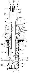
Number 1 in Figure 1 indicates a foundation
structure of a building (not shown), which is built on
the ground 2 and is normally defined by a continuous
beam, a slab, or reinforced concrete footings. Foundation
structure 1 may obviously be used for a building, for any
other type of building structure (e.g. a bridge), and
more generally for any structure requiring a ground
foundation (e.g. a hydraulic turbine, industrial boiler,
or electric pylons).
Foundation structure 1 is normally buried, and
transfers the loads on it to ground 2 by means of a
number of piles 3 (only one shown) extending through and
downwards from the structure. For which purpose, for each
pile 3, structure 1 comprises a substantially vertical
hole 4, of cylindrical or other shaped cross section, and
lined with a metal pipe 5, which is fixed to foundation
structure 1 by a ring 6 incorporated in structure 1, and
projects upwards from foundation structure 1 by a top
portion 7. A layer 8 of relatively poor, so-called "lean"
cement is preferably interposed between foundation
structure 1 and ground 2; and a number of fastening rings
6 may be provided at different levels.
In alternative embodiments depending on the
CA 02540185 2006-03-24
WO 2005/028759 PCT/IT2003/000568
- 6 -
construction characteristics of the building, foundation
structure 1 may be built either entirely, or from an
existing structure in which, for example, holes 4 are
formed. To increase the mechanical strength of an
existing foundation structure 1, or to construct a
foundation structure 1 of reduced thickness, each hole 4
may be surrounded by a metal plate, which obviously has a
central hole at hole 4, is connected to foundation
structure 1 by means of screws, and preferably rests on
the top surface of foundation structure 1.
Each pile 3 is made of metal, and comprises a
substantially constant-section rod 9, normally defined by
a number of tubular segments of equal length welded end
to end; and at least one wide bottom main head 10
defining the bottom end of pile 3. Rod 9 may obviously be
other than circular in section, and may also be solid.
Each rod 9 is tubular in shape, has a through inner
conduit 11, and is smaller across than relative hole 4 so
as to fit relatively easily through hole 4. Each main
head 10 is defined by a flat, substantially circular
plate 12 having a jagged outer edge 13 (Figure 2), but
which may obviously be shaped differently, e.g. circular,
square or rectangular, with a jagged or smooth edge. Each
main head 10 is larger or the same size across as
relative hole 4, is initially detached from respective
rod 9, and, when constructing foundation structure 1, is
placed substantially contacting ground 2 beneath
foundation structure 1, and coaxial with relative hole 4
CA 02540185 2006-03-24
WO 2005/028759 PCT/IT2003/000568
7 -
(as shown in Figure 3) . Consequently, each rod 9, as it
is fitted through relative hole 4, engages relative main
head 10 to form relative pile 3.
In the case of an existing foundation structure 1,
to install main head 10, a hole is formed in foundation
structure 1, which is then partly restored to obtain a
hole 4 smaller across than main head 10.
To ensure sufficiently firm mechanical connection of
each rod 9 and relative main head 10, main head 10 is
provided with a connecting member 14, which engages rod 9
to fix rod 9 transversely to main head 10. In the
embodiments shown, for example, each connecting member 14
is defined by a cylindrical tubular member projecting
axially from plate 12 and so sized as to engage a bottom
portion of inner conduit 11 of relative rod 9 with fairly
little clearance. Connecting member 14 may obviously be
formed differently.
A bottom end portion of each pipe 5 is fitted with
at least one sealing ring 15, which is made of elastic
material and engages the outer cylindrical surface of rod
9 of pile 3, when pile 3 is fitted through corresponding
hole 4.
When building foundation structure 1, at least one
injection conduit 16 is formed at each hole 4, is defined
by a metal pipe 17 extending through foundation structure
1, and has a top end 18 projecting from structure 1, and
a bottom end 19 adjacent to hole 4 and contacting a top
surface 20 of plate 12 of relative main head 10.
CA 02540185 2006-03-24
WO 2005/028759 PCT/IT2003/000568
- S -
To drive each pile 3 into ground 2, relative rod 9
is first inserted through relative hole 4 to engage (as
described previously) relative main head 10 located
beneath foundation structure 1, contacting ground 2, and
coaxial with relative hole 4.
As shown in Figure 1, once rod 9 engages relative
main head 10 to define relative pile 3, a thrust device
21, which cooperates with a top end 22 of pile 3, is set
up over pile 3 and connected to projecting portion 7 of
relative pipe 5 by means of two ties 23 threaded at the
top. More specifically, thrust device 21 is defined by at
least one hydraulic jack comprising a body 24, and an
output rod 25 movable axially with adjustable force with
respect to body 24. Body 24 is supported on top end 22 of
pile 3, and rod 25 is brought into contact with a bottom
surface of a metal plate 26 fitted through with ties 23
and made axially integral with ties 23 by means of
respective bolts 27 engaging the threaded top portions of
ties 23.
Once fitted to pile 3 as described above, thrust
device 21 is activated to generate a force of given
intensity between body 24 and rod 25, which force
produces static thrust, of the same intensity as the
force, on pile 3 to drive it into ground 2. The reaction
to the thrust exerted by thrust device 21 is provided by
the weight of foundation structure 1 (to which
appropriate ballast resting on foundation structure 1 may
be added) and is transmitted by ties 23, which, together
CA 02540185 2006-03-24
WO 2005/028759 9 _ PCT/IT2003/000568
with relative pipe 5, act as reaction members by
maintaining a fixed distance between plate 26 and
foundation structure 1 as rod 25 is extracted from body
24, so that body 24 is forced downwards together with top
end 22 of pile 3.
Thrust device 21 may obviously be formed
differently, providing static thrust is exerted on pile 3
to drive it into ground 2. For example, thrust device 21
may comprise two hydraulic jacks on opposite sides of rod
9; the movable rod of each hydraulic jack is fixed to a
horizontal plate connected rigidly to pipe 5 and,
therefore, to foundation structure 1; and the bodies of
the two hydraulic jacks engage and grip rod 9 between
them so as to draw rod 9 down as the hydraulic jack rods
are extracted from the bodies. More specifically, the
bodies of the two hydraulic jacks grip rod 9 by means of
wedges which compress rod 9 as the hydraulic jack bodies
move down. When the jack rods are fully extended, the
gripping action on rod 9 is eliminated by reducing the
pressure on the wedges, and the jack rods return to the
starting position to continue driving rod 9.
In an alternative embodiment not shown, as opposed
to being connected to the projecting portion 7 of pipe 5,
ties 23 of thrust device 21 are connected to physically
separate drive ballast not resting on foundation
structure 1, so that the reaction member for driving pile
3 is defined, not by foundation structure 1, but solely
by the drive ballast. Alternatively, the reaction member
CA 02540185 2006-03-24
WO 2005/028759 PCT/IT2003/000568
- 10 -
may be defined by both foundation structure 1 and the
drive ballast, which, as stated, is physically separate
from, as opposed to resting on, foundation structure 1.
To increase the reaction force generated by the drive
ballast, without recourse to excessively heavy drive
ballast (which would be bulky and difficult to move), the
drive ballast may be secured to ground 2 by screws driven
temporarily into ground 2 outside foundation structure 1.
The drive ballast may also be defined by a movable body,
e.g. a wheel-mounted truck or a barge or pontoon, which
can be positioned easily close to hole 4, or may be
defined by auxiliary piles or screws driven temporarily
into ground 2 to act as reaction members when driving
pile 3, and which are removed once pile 3 is driven.
The above embodiment is obviously used to avoid
stressing a particularly fragile foundation structure 1.
As each pile 3 is driven into ground 2, main head 10
forms in ground 2 a channel 28 of substantially the same
shape and transverse dimensions as main head 10 itself.
Channel 28 is divided into an inner cylindrical portion
29 occupied by relative rod 9; and a substantially clear
outer tubular portion 30, into which, as pile 3 is being
driven into ground 2, substantially plastic cement
material 31 is pressure-injected simultaneously along
relative injection conduit 16. More specifically, cement
material 31 substantially comprises cement and sand or
so-called "betoncino", which is a concrete having
features similar to the mortar; 1 cube meter of
CA 02540185 2006-03-24
WO 2005/028759 PCT/IT2003/000568
- 11 -
"betoncino" is made by 550 Kg of Portland-type cement,
150 Kg of water, 1425 Kg of sand, and some fluidises) so
as to be particularly fluid for easy pressure-injection
along injection conduit 16. A number of injection
conduits 16 may obviously be provided for each pile 3, to
supply cement material 31 either simultaneously or
successively.
Sealing ring 15 prevents the pressure-injected
cement material 31 from seeping upwards through the gap
between the outer surface of rod 9 and the inner surface
of relative pipe 5.
In an alternative embodiment, cement material 31 may
contain additives (e.g. bentonite) to reduce adhesion of
ground 2 to cement material 31 as it dries. Such
additives may be used when ground 2 has a tendency to
shrink over time (e.g. as in the case of peat layers). In
which case, preventing adhesion to cement material 31
allows ground 2 to eventually shrink freely and
naturally.
In a further embodiment, cement material 31 contains
waterproofing additives, which make it substantially
impermeable to water even prior to curing. Such additives
are necessary when pile 3 is driven through a water bed,
particularly containing high-pressure and/or relatively
fast-flowing water, and serve to prevent water from
mixing with and so deteriorating cement material 31.
Tests have also shown that, when working through a moving
water bed, it is important to inject cement material 31
CA 02540185 2006-03-24
WO 2005/028759 PCT/IT2003/000568
- 12 -
at a higher pressure than that exerted by the moving
water, so as to further reduce the likelihood of water
mixing with cement material 31.
As stated, each rod 9 is divided into a number of
segments, which are driven successively, as described,
through relative hole 4, and are welded together to
define pile 3. More specifically, once a first segment of
rod 9 is driven, thrust device 21 is detached from the
top end of the first segment to insert a second segment,
which is butt welded to the first segment; thrust device
21 is then connected to the top end of the second segment
to continue the drive cycle. In an alternative embodiment
not shown, two successive tubular segments are fixed
together by a connecting portion, which partly engages
the inner conduits of the two segments. The component
segments of each rod 9 are normally identical, but, in
certain situations, may differ in length, shape or
thickness.
Depending on the structural characteristics of
foundation structure 1 and the characteristics of ground
2, each pile 3 is assigned a rated capacity, i.e. a
weight which must be supported by pile 3 without
yielding, i.e. without breaking and/or sinking further
into ground 2. To ensure the rated capacity is met, each
pile 3 is normally driven until it is able to withstand
thrust by thrust device 21 in excess of the rated
capacity without sinking further into ground 2. This is
made possible by piles 3 being driven into ground 2 one
CA 02540185 2006-03-24
WO 2005/028759 PCT/IT2003/000568
- 13 -
at a time. When driving each pile 3, therefore,
practically the whole weight of foundation structure 1
(to which appropriate ballast may be added) can be used
as a reaction force to the thrust exerted by relative
thrust device 21. As already stated, the reaction force
may of course be provided wholly or partly by drive
ballast independent of foundation structure 1.
As shown in Figure 4, once each pile 3 is driven,
the corresponding thrust device 21 is removed from pile
3, and the relative inner conduit 11 is filled with
substantially plastic cement material 32, in particular
"concrete". Once the inner conduit 11 of each pile 3 is
filled, pile 3 is fixed axially to foundation structure 1
by securing (normally welding) to the projecting portion
7 of relative lining pipe 5 a horizontal metal plate 33
(or an annular flange), which is fitted on top of pile 3
to engage top end 22.
In a further embodiment not shown, rod 9 is not
filled with cement material 32, and, as opposed to having
a tubular section, is preferably solid with no inner
conduit 11.
In an alternative embodiment not shown, a body of
elastic material (e.g. neoprene) is inserted inside
lining pipe 5 and between top end 22 of pile 3 and metal
plate 33, generally for the purpose of improving
earthquake resistance of foundation structure 1.
In a further embodiment not shown, each pile 3 is
driven so that top end 22 is below the top surface of
CA 02540185 2006-03-24
WO 2005/028759 PCT/IT2003/000568
- 14 -
foundation structure 1; projecting portion 7 of pipe 5 is
then cut; and plate 33 is fixed to the rest of pipe 5 so
as to be substantially coplanar with the top surface of
foundation structure 1, and so obtain a foundation
structure 1 with a fully walk-on top surface.
Before being fixed axially to foundation structure
1, pile 3 can be preloaded with a downward thrust of
given intensity throughout the time taken to weld metal
plate 33 to lining pipe 5. In other" words, pile 3 is
subjected to downward thrust of given intensity while
welding metal plate 33 to lining pipe 5. Preloading pile
3 as it is being fixed to foundation structure 1 allows
any yield of pile 3 to occur rapidly as opposed to over a
long period of time. Rectifying any yield of one or more
piles 3 is a relatively straightforward, low-cost job
when building foundation structure 1, but is much more
complex and expensive once foundation structure 1 is
completed.
In soft ground, such as silt or peat, channel 28,
formed by main head 10 as it is driven into ground 2, may
be partly or completely clogged by so-called "caving"
portions of ground 2, which are pushed inside channel 28
by the pressure exerted by main head 10 on ground 2. The
caving ground clogging channel 28 prevents portion 30
from being filled completely with cement material 31,
thus impairing, even seriously, the final capacity of
pile 3. The caving phenomenon is in direct proportion to
the softness of ground 2 and the pressure exerted on
CA 02540185 2006-03-24
WO 2005/028759 PCT/IT2003/000568
- 15 -
ground 2 by main head 10.
The above drawback is solved using the embodiment
shown in Figures 5 and 6, in which, in addition to main
head 10, pile 3 also comprises a lead-in head 34 located
beneath foundation structure 1, beneath and coaxial with
main head 10 (Figure 5). Lead-in head 34 comprises a
circular plate 35 connected to a tubular body 36, which
extends upwards through a circular opening 37 in main
head 10, and engages a bottom end 38 of rod 9. Tubular
body 36 is so sized across as to be partly insertable
inside conduit 11 of rod 9 inserted through hole 4; and
insertion of tubular body 36 inside rod 9 is arrested by
a ring 39 fixed to the outer surface of tubular body 36.
In actual use, rod 9 is inserted inside hole 4 and
engages the top portion of tubular body 36 as described
above; as bottom end 38 of rod 9 contacts ring 39,
further downward movement of rod 9 produces an equal
downward movement of tubular body 36, which slides inside
opening 37 and pushes lead-in head 34 down into ground 2,
while main head 10 initially remains stationary in its
original position.
As it continues moving down, the bottom end 38 of
rod 9, with ring 39 in between, contacts the top end of
connecting member 14 of main head 10, thus also pushing
main head 10 down into ground 2.
Main head 10, in particular plate 12, is slightly
larger across than lead-in head 34, in particular plate
of lead-in head 34, so that main head 10 is maintained
CA 02540185 2006-03-24
WO 2005/028759 - 16 - PCT/IT2003/000568
a constant distance from lead-in head 34 at all times
when driving pile 3 into ground 2.
As pile 3 is driven into ground 2, lead-in head 34
exerts considerable pressure on ground 2, and forms, in
ground 2, a channel 40 which is therefore highly
susceptible to said caving phenomenon (indicated 41 in
Figure 6). Main head 10, on the other hand, exerts
relatively little pressure on ground 2, and so provides
for "reaming" channel 40 and forming channel 28, which is
therefore less susceptible to caving, so that cement
material 31 fed into portion 30 encounters substantially
no obstacles.
As pile 3 is driven into ground 2, at least 1 metre
distance is maintained between main head 10 and lead-in
head 34 to prevent caving of channel 28 caused by the
pressure exerted on ground 2 by lead-in head 34.
In the Figure 1-4 embodiment, pile 3 comprises one
main head 10 which, as it is driven in, forms in ground 2
channel 28 which is filled with cement material 31. In
the Figure 5 and 6 embodiment, pile 3 comprises main head
10 which, as it is driven in, forms in ground 2 channel
28 which is filled with cement material 31; and lead-in
head 34 which, as it is driven in, forms in ground 2
channel 40 which defines a "lead-in" channel by which to
drive in main head 10.
In a further embodiment not shown, pile 3 comprises
main head 10 which, as it is driven in, forms in ground 2
channel 28 which is filled with cement material 31; and a
CA 02540185 2006-03-24
WO 2005/028759 - 17 - PCT/1T2003/000568
number of (normally two to four) lead-in heads 34 which,
as they are driven in, form in ground 2 channel 40 which
defines a "lead-in" channel by which to drive in main
head 10. The transverse dimensions of lead-in heads 34
increase gradually to gradually increase the transverse
dimensions of channel 40; and the number of lead-in heads
34 used depends on the type of ground 2. In special
cases, the transverse dimensions of lead-in heads 34 may
decrease gradually, so as to have a very wide bottom
lead-in head 34 and a wide supporting base, and a smaller
main head 10 and/or smaller upper lead-in heads 34 to
reduce the size of channel 30 and therefore the amount of
cement material 31 injected into ground 2.
In an alternative embodiment, cement material 31 may
be injected into channel 40 formed by driving a lead-in
head 34 into ground 2; in which case, the injection
conduit used (not shown in detail) is identical to
injection conduit 50 shown in the Figure 11 embodiment,
and is defined by a pipe having a bottom end located at a
through hole in tubular body 36, and a top end connected
to an injection device.
Each pile 3 may therefore have more than one main
head 10 and more than one lead-in head 34, which heads 10
and 34 may be of different sizes and different distances
apart. Moreover, the transverse dimensions of each main
head 10 or lead-in head 34 may vary both in the course of
and after driving pile 3; and the channel formed by
driving any one main head 10 or lead-in head 34 may be
CA 02540185 2006-03-24
WO 2005/028759 PCT/IT2003/000568
- 18 -
filled with cement material 31 in one stage or in a
number of successive time-separated stages.
In an alternative embodiment, a lead-in head 34 is
fixed to and made slidable with respect to respective
tubular body 36 by a connecting mechanism. That is, when
driving pile 3, it may be decided to arrest the downward
movement of lead-in head 34 at a certain point, and
continue solely with the downward movement of tubular
body 36. The connecting mechanism may be remote
controlled by an actuator, or may be designed to release
slide of lead-in head 34 with respect to tubular body 36
when the force exerted on lead-in head 34 exceeds a
predetermined threshold value. Similarly, main head 10
may be fixed to and made slidable with respect to rod 9
by a connecting mechanism. That is, when driving pile 3,
it may be decided to arrest the downward movement of main
head 10 at a certain point, and continue solely with the
downward movement of rod 9. The connecting mechanism may
be remote controlled by an actuator, or may be designed
to release slide of main head 10 with respect to rod 9
when the force exerted on main head 10 exceeds a
predetermined threshold value.
In the alternative embodiment shown in Figure 7, the
bottom portion of main head 10 is pointed. More
specifically, the underside of plate 12 of main head 10
is fitted rigidly with a pointed body 42, which may be
conical or wedge-shaped or any other shape terminating in
a pointed tip. The inclination of the tip of body 42 may
CA 02540185 2006-03-24
WO 2005/028759 PCT/IT2003/000568
- 19
be fixed or variable (in particular, may click between
two positions) for adjustment, when driving pile 3, as a
function of the characteristics of ground 2 being worked
by main head 10. In other words, at any time when driving
the pile, the inclination of the tip of body 42 may be
varied to adapt to the characteristics of ground 2 being
worked at that time by main head 10.
A pointed main head 10 has the advantage of being
driven into ground 2 more easily, and above all of
preventing downward thrust of the portion of ground 2
dislodged by main head 10 as it is driven in. That is, as
the pointed main head 10 moves down, the portion of
ground 2 dislodged by main head 10 tends to slide along
the sloping walls of the tip and be pushed away on either
side of main head 10. In other words, in the case of a
flat main head 10, the portion of ground 2 dislodged as
main head 10 moves down tends to be at least partly
pushed down by main head 10; whereas, in the case of a
pointed main head 10, the portion of ground 2 dislodged
as main head 10 moves down tends, as stated, to slide
along the sloping walls of the tip to either side of main
head 10.
Preventing downward thrust of the portion of ground
2 dislodged as main head 10 moves down is extremely
important when driving main head 10 through two layers of
different compositions, which must be prevented from
mixing. This situation normally occurs in the presence of
a water bed, which must be safeguarded against pollution
CA 02540185 2006-03-24
WO 2005/028759 PCT/IT2003/000568
- 20 -
by entrained material from the layers of ground 2 above
the bed.
In the case of a pile 3 comprising a main head 10
and a number of lead-in heads 34, only the bottom lead-in
head 34 can be pointed. Alternatively, as shown in Figure
8, the lead-in heads 34 and main head 10 are all pointed
(fixed or adjustable), but obviously only the bottom
lead-in head 34 is fully pointed, while the other lead-in
heads 34 and the main head 10 are pointed with a centre
hole for passage of the lower lead-in heads 34.
As it is being driven into ground 2, main head 10
may be rotated at a given, normally variable, speed about
its central axis to assist penetration of ground 2 by
main head 10. Rotation is particularly useful in the case
of a pointed main head 10, in which case, main head 10
preferably comprises a number of helical grooves to screw
main head 10 into ground 2. Alternatively, main head 10
may be screwed into ground 2 with or without material
extraction from channel 28. Material extraction from
channel 28 is particularly useful to overcome layers of
particularly tough ground.
When driving pile 3, rod 9 of pile 3 may be rotated
slightly about its vertical axis to compensate for any
deviation of rod 9 with respect to the vertical, caused
by being driven through particularly tough points of
ground 2, such as concrete headers or boulders.
In the Figure 9 embodiment, in the event ground 2
comprises a highly compact, tough upper layer 43, and a
CA 02540185 2006-03-24
WO 2005/028759 PCT/IT2003/000568
- 21 -
less compact, softer lower layer 44, a pre-channel 45 may
be formed through upper layer 43 using a normal drill
(possibly with bits increasing gradually in size). Pre-
channel 45 is obviously coaxial , with pipe 5, and
therefore with main head 10 and with channel 28 formed by
driving main head 10 into ground 2, and provides for
driving main head 10 more easily into upper layer 43 of
ground 2.
Pre-channel 45 may be smaller, the same size, or
slightly larger across than main head 10, and may be
filled with low-strength material 46 (e.g. sand) to
ensure correct formation of pile 3, and to prevent ground
2 from caving in and clogging pre-channel 45 with
heterogeneous material (e.g. rubble) which might hinder
the downward movement of main head 10. In the preferred
embodiment shown in Figure 9, pre-channel 45 is slightly
larger across than main head 10, and is lined with a
liner 47 of sheet metal (or other material, such as PVC)
to prevent ground 2 from caving into pre-channel 45. Once
sheet metal liner 47 is in place, pre-channel 45 is
filled with low-strength material 46 to ensure correct
formation of pile 3. It is important, in fact, that, as
it moves down, main head 10 should encounter as little
resistance as possible, so as to exert sufficient
pressure on ground 2 to compact it locally.
Obviously, if the same size across as main head 10.
i.e. if larger across than hole 4, pre-channel 45 must be
formed before building foundation structure 1. When
CA 02540185 2006-03-24
WO 2005/028759 PCT/IT2003/000568
- 22 -
driving main head 10, pre-channel 45 may be at least
partly flooded with water; in which case, the water may
be sucked out of pre-channel 45 along injection conduit
16, possibly by inserting a pipe connected along
injection conduit 16 to a suction pump.
In the event ground 2 comprises weak (e.g. clay)
layers alternating with tough (e.g. sand) layers, to
maintain a relatively constant drive pressure of pile 3,
the transverse dimension of main head 10 or lead-in heads
34 may be varied as a function of the compactness of the
layer of ground 2 being worked by main head 10. In other
words, when main head 10 encounters a particularly
compact layer of ground 2, the transverse dimension of
main head 10 is reduced to a given minimum; and,
conversely, when main head 10 encounters a soft layer of
ground 2, the transverse dimension of main head 10 is
increased to a given maximum. The transverse dimension of
main head 10 may be increased or reduced, for example, by
means of an actuator for producing relative slide between
at least two peripheral portions of plate 12 of main head
10. Varying the transverse dimension of main head 10, as
it is driven in, also varies the transverse dimension of
channel 28.
The variable transverse dimension of main head 10
may be made use of when building foundation structure 1.
That is, as opposed to being aligned with hole 4 beneath
foundation structure 1, main head 10 is inserted through
hole 4 when driving pile 3, and is then expanded on
CA 02540185 2006-03-24
WO 2005/028759 PCT/IT2003/000568
- 23 -
contacting ground 2. In other words, main head 10 is
contracted to a smaller transverse dimension than hole 4
so as to fit through hole 4, and is then expanded to a
larger transverse dimension than hole 4 to form channel
28. This solution is particularly useful when working
with an existing foundation structure 1.
In an alternative embodiment, the possibility,
described above, of varying the transverse dimension of
main head 10, as it is driven into ground 2, may also be
used to increase the transverse dimension of the end
portion of channel 28, and so form a relatively- wide- bulb
at the bottom end portion of pile 3 to increase the
ground supporting surface, and hence, the capacity of
pile 3. Alternatively, the transverse dimension of the
end portion of pile 3 may be increased to form such a
bulb by pulling main head 10 upwards to deform the end
portion of rod 9.
As shown in Figure 10, when building foundation
structure 1, an insulating sheath 48 is interposed
between foundation structure 1 and ground 2 (or between
foundation structure 1 and lean cement layer 8, if any)
to protect foundation structure 1 from infiltration by
water. At each hole 4, insulating sheath 48 obviously
comprises a corresponding hole for the passage of
relative pile 3. More specifically, insulating sheath 48
is fixed to respective lining pipe 5 by inserting the
free edge of sheath 48 between two rings 6, and inserting
through insulating sheath 48 a number of screws 49, each
CA 02540185 2006-03-24
WO 2005/028759 PCT/IT2003/000568
- 24 -
of which is bolted to the two rings 6. Though not
illustrated in detail, a similar fastening system may
also be used to fix sheath 48 to pipe 17 of injection
conduit 16.
In the Figure 11 embodiment, injection conduit 16
shown in the previous drawings is eliminated, and cement
material 31 is injected into outer tubular portion 30 of
channel 28 by an injection conduit 50, which is defined
by a pipe 51 made of flexible material and having a
bottom end at a through hole 52 in rod 9, and a top end
connected to an injection device (not shown). Hole 52 is
located close to main head 10 to inject cement material
31 into outer tubular portion 30 of channel 28 upwards,
as opposed to downwards like injection conduit 16.
Injecting cement material 31 upwards as opposed to
downwards has the advantage of forming "enlargements" of
cement material 31 at various heights. In the preferred
embodiment shown in Figure 11, a number of holes 52 are
provided at the same height and symmetrically about the
central axis of rod 9, so as to inject cement material 31
simultaneously from a number of points. In an alternative
embodiment not shown, holes 52 are located at different
heights along rod 9, and may be fed by one or more pipes
51, when driving pile 3 (possibly in a number of non-
simultaneous stages) or even after pile 3 is driven. Once
cement material 31 is injected, pipe 51 can either be
removed from or left inside conduit 11 of rod 9.
It is important to note that, prior to driving pile
CA 02540185 2006-03-24
WO 2005/028759 PCT/IT2003/000568
- 25 -
3, any water beneath foundation structure 1 can be sucked
out along injection conduit 16 or 50.
In the Figure 12-14 embodiment, prior to inserting
rod 9 inside respective hole 4, a beam 53, preferably an
I-beam (shown clearly in Figure 13), is inserted inside
hole 4 and inside connecting member 14 of main head 10,
so as to face a through slot 54 formed in plate 12 of
main head 10 and shaped and sized to permit passage of
beam 53. Before rod 9 is inserted, the bottom end of beam
53 is fitted through slot 54 to rest on ground 2 in the
position shown in Figure 12.
A plate 55, at least as large across as rod 9, is
placed on the top end of beam 53. When rod 9 is inserted
inside hole 4, the bottom end of rod 9 rests on the top
surface of plate 55. When rod 9 is subjected to downward
thrust, this is transmitted by plate 55 to beam 53, which
therefore begins to sink into ground 2. As plate 55 comes
to rest on the top end of connecting member 14, the
downward thrust on rod 9 is transferred to both main head
10 and beam 53, which both sink together into ground 2 as
shown in Figure 14. Obviously, in an alternative
embodiment not shown, beam 53 may be replaced by an
elongated member of any type, e.g. a tubular member or
channel section.
The purpose of beam 53 is to define a bottom
extension of pile 3 with respect to main head 10. This is
useful when the downward movement of main head 10 is
arrested by main head 10 coming to rest on a particularly
CA 02540185 2006-03-24
WO 2005/028759 PCT/IT2003/000568
- 26 -
compact, tough, deep ground layer; in which case, beam 53
penetrates the deep layer of ground 2 beneath main head
to increase the capacity of pile 3.
As stated above, varying the transverse dimension of
5 main head 10 (and possibly also of a lead-in head 34),
when sinking main head 10, also varies the transverse
dimension of channel 28, thus enabling the formation of a
pile 3 varying freely in transverse dimensions along its
longitudinal axis. In other words, pile 3 may comprise,
10 about rod 9, intermediate or end segments of cement
material 31 larger across than the rest of pile 3 and
commonly referred to as "enlargements".
Besides varying the transverse dimension of main
head 10 (and possibly also of a lead-in head 34) when
driving the pile, "enlargements", i.e. intermediate or
end segments of cement material 31 larger across than the
rest of pile 3, can also be formed using the Figure 11
embodiment, in which cement material 31 is injected into
channel 28 through one or more holes 52 located along rod
9, and by varying the quantity and pressure of cement
material 31 injected when driving pile 3. As stated,
material may be fed through holes 52 while driving pile 3
(possibly in a number of non-simultaneous stages) or even
after pile 3 is driven.
It is important to stress that rod 9 is normally
formed by joining a number of segments driven
successively into ground 2. As such, the thickness of the
various component segments of rod 9 may also be varied,
CA 02540185 2006-03-24
WO 2005/028759 PCT/IT2003/000568
- 27 -
so as to obtain, along the longitudinal axis of pile 3,
not only different thicknesses of cement material 31, but
also different thicknesses of metal rod 9.
In an alternative embodiment not shown, main head 10
is substantially the same size across as rod 9, and is
pointed as described previously. Obviously, in this
embodiment, the channel 28 formed by the pointed main
head 10 penetrating ground 2 when driving pile 3 is the
same size across as rod 9, so that no cement material 31
can be injected. This embodiment is used when pile 3 is
driven into waterlogged or underwater ground 2.
. When building foundation structure 1 or driving
piles 3, temporary piles (not shown in detail) may need
to be driven into ground 2 to form, for example,
temporary structures, and which must be removed once work
is completed. To extract a temporary pile from ground 2,
a method similar to that described for driving piles 3
may be used. That is, the temporary pile is subjected to
static pull generated by an extracting device connected
mechanically at one end to the top end of the temporary
pile, and resting at the other end on foundation
structure 1, which acts as a reaction member for the
extracting device. More specifically, the extracting
device preferably comprises at least two hydraulic jacks
on opposite sides of the temporary pile; the movable rod
of each hydraulic jack is fixed to a horizontal plate
connected rigidly to the temporary pile; and the bodies
of the two hydraulic jacks rest on foundation structure
CA 02540185 2006-03-24
WO 2005/028759 - 28 - PCT/IT2003/000568
1.
The above description illustrates numerous
embodiments by which to form each pile 3, and the
characteristics of which may obviously be variously
combined, depending on the characteristics of the
building, the characteristics of ground 2, and the
desired end result.
As will be clear from the foregoing description,
each pile 3 typically comprises a cylindrical metal core
(rod 9) filled with concrete 32 and enclosed in a jacket
of betoncino 31. Each pile 3 is driven statically with
substantially no material being extracted from ground 2,
and is sunk into ground 2 by simply compacting the
regions through which it travels. As such, ground 2 on
which the pile foundation stands is renewed and
compacted, and a substantially clean construction site is
obtained by eliminating the earth-moving and excavation
work required by drilled piles.
It should be pointed out that, being performed
statically using hydraulic jacks, each pile 3 is driven
with absolutely no vibration or noise, so that the static
and stability of any buildings in the vicinity of
foundation structure 1 are in no way affected.
Finally, it should be noted that, by building
foundation structure 1 shortly before the pile
foundation, overall work time can be reduced by
simultaneously driving piles 3 and constructing the
superstructures (not shown) supported by foundation
CA 02540185 2006-03-24
WO 2005/028759 _ 29 r PCT/IT2003/000568
structure 1.