Note : Les descriptions sont présentées dans la langue officielle dans laquelle elles ont été soumises.
CA 02540443 2006-O1-10
SPECIFICATION
CONTINUOUS TRANSFER TYPE FREEZER
Technical field
The present invention relates to a transfer type freezer
capable of continuous cooling or continuous freezing; in which
a chilled air jet is impinged on an article transferred on
a conveyer belt, whereby a thin stream layer is formed on
the surface of the article owing to Coanda effect resulting
in higher cooling effect: in which exhaust passages are formed
for guiding the air impinged on the article in both width
directions of the belt; and in which apparatuses are located
in a single space surrounded by the housing, whereby the
chilled air can circulate in the housing more easily, its
flow loss is reduced, and maintenance such as cleaning can
be performed easily.
Background art
A method to cool, heat, or dry an article such as foodstuffs
as it is transferred on a belt conveyor in an oblong housing
has been disclosed in prior arts, in which a gas jet is allowed
to impinge on the article. In those prior arts, a chilled
air is spouted from hole nozzles or slit nozzles perpendicular
to the surface of the belt and a thin stream layer is formed
on the surface of the article placed on the belt owing to
Coanda effect, by which heat transfer between the chilled
air and the surface of the article is increased.
For example, a transfer type freezer is disclosed in
Japanese Patent Application Publication.No.8-507596(prior
1
CA 02540443 2006-O1-10
art 1), in which a tunnel is provided in a housing having
an entrance and exit opening for a conveyor belt to surround
the conveyor belt with the upper wall, two side walls extending
along the transfer direction of the conveyor belt, and the
bottom wall of the tunnel, the inside of the tunnel is
vacuumized by a gas sucking means to form gas circulation
in the housing such that the gas in the housing flows through
holes formed in said upper wall into the tunnel, exits from
the tunnel through an opening formed in said bottom wall,
and again flows into the tunnel through said holes, thus a
gas j et stream is formed to impinge against the article placed
on the conveyor belt.
FIG.7 is a schematic representation of the equipment of
said prior art 1 for explaining the principle of operation
thereof, and FIG.7 (a) is a partial enlarged detail of FIG.7 .
The equipment comprises a housing O1, in which a tunnel
02 is provided to surround a treating zone 03. The gas in
the treating zone 03 is sucked by a sucking means 04 to vacuumize
the treating zone. A conveyor belt 05 transfers foodstuffs
06 through the tunnel.
In FIG.7, holes are bored only in the upper wall 07 of
the tunnel 02, the upper and lower surfaces of the upper wall
being flat and nozzles being formed without no part protruding
from the upper and lower surfaces of the upper wall (see FIG. 7a) .
In a preferable embodiment, holes are bored also in the bottom
wall of the tunnel 02.
During operation of the equipment, the sucking means 04
vacuumize the inside space of the tunnel 02 so that the air
in the housing is sucked through the nozzles 8 in the upper
wall 07 and air jets 09 are formed to impinge against the
2
CA 02540443 2006-O1-10
conveyor belt 05 and the foodstuffs 06 placed thereon.
In Japanese Laid-Open Patent Application No.ll-63777
(prior art 2) is disclosed a transfer type freezer in which
articles such as foodstuffs are placed on a conveyor belt
passing through an oblong housing, a number of slits to produce
jet streams are formed in an upper and lower plates facing
the conveyor belt, the jet streams of chilled air impinge
on the articles to cool or freeze them, and the chilled air
that has cooled the articles is exhausted in one direction.
With said prior art 1, a vacuum chamber is necessary to
be provided in order to vacuumize the tunnel surrounding the
conveyor belt. For this purpose, a large fan is required as
a sacking means and large power is needed to drive the fan.
Further, as air jet streams are formed by sacking air by the
fan through the holes bored in the upper wall, the jet flows
lack in directionality and tend to diffuse or proliferate.
Therefore, the air jet streams do not necessarily impinge
on the articles at high speed resulting in low heat transfer
between the air and the surface of the articles.
Further, air exit openings are provided below the conveyor
belt at certain intervals, so nozzles can not be provided
where the exit openings are provided under the conveyor belt,
resulting in decreased cooling efficiency. There is no air
exit opening above the conveyor belt and the air introduced
into the tunnel through the nozzles (holes) bored in the upper
wall must flow through the holes bored in the conveyor belt
to be exhausted from the tunnel. Therefore, the conveyor belt
must have holes and a conveyor belt not having holes can not
be used. Therefore, loading density of the articles
3
CA 02540443 2006-O1-10
transferred on the belt is limited, because there must be
left on the belt space not occupied by the articles in order
to allow the air introduced into the tunnel through the
nozzles(holes) to flow downward through the holes of the
conveyor belt.
According to the prior art 2, chilled air jets impinge
against both upper surface and undersurface of the conveyor
belt and then the chilled air is exhausted in one direction
perpendicular to the belt transfer direction, the air jets
tend to incline to said exhausting direction, which causes
reduction in heat transfer coefficient between the chilled
air and the surface of the article on the belt. Further, the
space in which the conveyor belt passes through is narrow
and inconvenient to clean. Therefore, it is necessary to
provide a number of cleaning nozzles, and the installation
becomes complicated resulting in increased cost.
Disclosure of the Invention
The present invention is made in light of the problems
mentioned above. An object of the invention is to achieve
high heat transfer between the chilled air and the surface
of the article to be cooled on a conveyor belt by spouting
chilled air from slit nozzles provided above and under a
conveyor belt in the form of air j ets toward both surfaces
of the conveyor belt in the direction perpendicular to the
surfaces of the belt, whereby thin chilled air stream layer
is formed on the surface of the article by virtue of Coanda
effect, resulting in increased heat transfer coefficient
between the chilled air and the surface of the article.
The second object of the invention is to increase heat
4
CA 02540443 2006-O1-10
transfer coefficient between the chilled air and the surface
of the article to increase cooling effect by allowing thin
air stream layer to be formed along the surface of the article
by virtue of Coanda effect even when the distance between
the nozzle opening and the article is relatively large through
rectifying the air flow in the nozzle and giving strong
directionality to the air jetted from the nozzle.
The third object of the invention is to provide a structure
with which the formation of passages for exhausting chilled
air does not constitute a limiting factor of providing nozzles
under the conveyor belt, for if the number of nozzles provided
under the conveyor belt is limited as is in said prior art
1, cooling effect is decreased.
The fourth object of the invention is to evade partitioning
the space in the housing and simplify the apparatuses in the
housing for generating the circulation of chilled air in the
housing so that flow loss of the chilled air circulation is
reduced and in addition inspection and maintenance such as
cleaning can be easily performed.
To attain the objects, the present invention proposes a
continuous transfer type freezer comprising a housing having
an entrance opening and an exit opening, a conveyor belt for
transferring articles to be cooled from said entrance opening
to said exit opening of the housing, a chilled air circulating
means consisting of a cooler .and a blower, and slit nozzles
for spouting chilled air against the articles to be cooled,
wherein a plurality of upper slit nozzles and lower slit
nozzles are apposed above and under the conveyor belt along
the direction of transfer of the belt with the slit of each
CA 02540443 2006-O1-10
nozzle perpendicular to the belt transfer direction, and
exhaust passages are formed perpendicular to the belt transfer
direction between each of the slit nozzles to guide the chilled
air spouted from the slit nozzles to both lateral end sides
of the conveyor belt.
According to the invention, as exhaust passages are formed
between each of a plurality of slit nozzles such that the
chilled air spouted from the slit nozzles is allowed to flow
toward both lateral end sides of the conveyor belt, the
formation of the exhaust passages does not constitute a
limiting factor of providing slit nozzles. Therefore, slit
nozzles can be located at positions most suited for the
articles on the belt and a thin air stream layer can be
positively formed on the surface of each article by virtue
of Coanda effect.
FIG.1 is a drawing for explaining the principle of Coanda
effect. In the drawing, when a film-like air stream 'k'
impinges, for example, on a cylindrical body 'A' in the
direction perpendicular to its surface, a thin, stable stream
layer 'S' is formed around the surface of the cylindrical
body 'A' . Therefore, when chilled air impinges on the surface,
heat transfer coefficient between the chilled air and the
surface of the cylindrical body 'A' is extremely increased
and cooling effect is improved.
Further, by forming exhaust passages to guide the chilled
air after it cooled the articles toward both lateral end sides
of the conveyor belt, inclined impingement of the air jets
spouting from the slit nozzles is evaded, the chilled air
after it cooled the article is exhausted smoothly toward both
lateral end sides of the conveyor belt, and the exhausted
6
CA 02540443 2006-O1-10
air can easily reach the inlet of the cooler for producing
chilled air.
In the invention, it is preferable that each of the slit
nozzles is shaped to have an entrance way consisting of a
tapered passage and a succeeding parallel passage. By
providing entrance way like this, chilled air stream in the
slit nozzle is rectified, directionality is given to the
spouting stream, and longitudinal coverage, or spray travel
of the air jet can be increased. This is explained by FIG.2.
In the drawing, slit nozzle 'n' is shaped to have an entrance
way constituting a tapered passage and a succeeding parallel
passage 'b' , and an air jet 'k' spouting from the nozzle opening
impinges against the article transferred on the conveyor belt
'c' at right angles.
The air jet 'k' spouting from the slit nozzle configured
like this has strong directionality and hardly diffuses, so
the longitudinal coverage 'h' of the air jet can be increased.
Therefore, chilled air stream can impinge on the article even
when the distance from the nozzle opening to the article is
fairly large.
In the invention, it is preferable that circulation of
air is generated in said housing such that chilled air flows
out from said blower to the space above the upper slit nozzles
in the housing, a large part of the chilled air flows to said
upper slit nozzles to be spouted from the upper slit nozzles
and exhausted through said exhaust passages, the remaining
part of the chilled air flows to said lower slit nozzles through
ducts having openings at both lateral end sides of the conveyor
belt to be spouted from said lower slit nozzles and exhausted
through said exhaust passages, and the exhausted air returns
7
CA 02540443 2006-O1-10
to said cooler.
In this way, the chilled air spouted from the slit nozzles
and cooled the articles is smoothly guided to both lateral
end sides of the belt passing through the exhaust passage
to be exhausted outside of the belt without disturbing the
air jets spouted against the articles or atmosphere around
the articles.
It is preferable that said exhaust passage is formed to
be a concave between adjacent slit nozzles. By forming the
exhaust passage like this, the formation of the exhaust passage
does not constitute a limiting factor of providing slit nozzles,
the exhaust passage can be formed very easily between adj acent
slit nozzles, and the chilled air cooling the article can
be exhausted smoothly from both lateral end sides of the belt
resulting in decreased flow loss.
In the invention, it is preferable that the leading end
part of slit nozzles located near the entrance opening or
exit opening of the housing is inclined in accordance with
the difference of pressure near the openings from outside
pressure.
When there is a difference between the pressure near the
entrance opening and that near the exit opening, there occurs
an air flow from the opening side of higher pressure toward
the opening side of lower pressure and the air may flow out
from the housing or outside air may flow into the housing.
By slanting slit nozzles located near the openings against
said air flow induced by the pressure difference between both
openings, said flowing out of air from the housing and flowing
in of outside air can be prevented. Thus, when there is
difference between pressuresnear both openings, said outflow
8
CA 02540443 2006-O1-10
and inflow of air can be shutoff by slanting some of the slit
nozzles near the entrance or exit openings.
Further, it is preferable that a plurality of said slit
nozzles are integrated into a slit nozzle unit. By this,
manufacturing and mounting of slit nozzles become easy.
It is preferable in addition of the construction described
above that the slit nozzle unit consisting of a plurality
of the slit nozzles and located above the conveyor belt is
placed on frames provided at both lateral end sides of the
conveyor belt. By composing like this, the upper slit nozzle
unit can be detached easily when performing cleaning the upper
surface of the conveyor belt and upper slit nozzles which
are apt to be contaminated by the article such as foodstuffs,
and also inspection and maintenance work becomes easy.
When leading end parts of the slit nozzles are inclined
and the slit nozzle unit with inclined slit nozzles is placed
on frames provided at both lateral end sides of the conveyor
belt, inclination of the leading end parts of slit nozzles
can be easily reversed only by changing the lateral direction
of the slit nozzle unit, that is, by lifting the unit, turning
it by 180° and replacing it on the frames.
Brief Description of the Dra~iags
FIG.1 is a drawing for explaining the principle of Coanda
effect.
FIG.2 is a perspective view of the slit nozzle.
FIG.3 is a perspective view of the first embodiment of
the present invention with partial cutaway.
FIG.4 is a perspective view of the first embodiment of
the present invention with partial cutaway viewed from anther
9
CA 02540443 2006-O1-10
direction.
FIG S is a perspective view showing the flow of chilled
air jets impinged against the article transferred on the
conveyor belt in the case of the first embodiment.
FIG.6 is a partially enlarged side view schematically
representing the second embodiment of the present invention,
and FIG.6(a) is an enlarged detail of a part indicated by
VIa in FIG.6.
FIG.7 is a schematic sectional view showing the working
principle of an apparatus of prior art, and FIG.7(a) is an
enlarged detail of FIG.7.
Bast mode for embodiment of the Invention
A preferred embodiment of the present invention will now
be detailed with reference to the accompanying drawings. It
is intended, however, that unless particularly specified,
dimensions, materials, relative positions and so forth of
the constituent parts in the embodiments shall be interpreted
as illustrative only not as limitative of the scope of the
present invention.
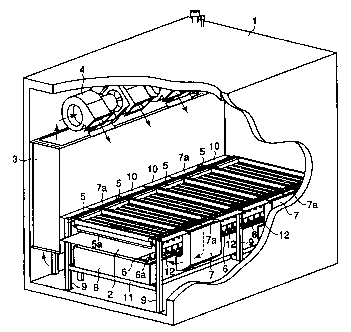
Referring to FIG.3 and FIG.4 showing the first embodiment
of the present invention, reference numeral 1 is a housing
which is preferably composed of heat insulating walls. The
housing is closed except an entrance opening and an exit
opening not shown in the drawings for entrance and exit of
a conveyor belt 2. Chilled air is circulated in the housing.
Reference numeral 3 is a cooler and 4 are cooling fans to
constitute a part of a chilled air cycle.
Reference numeral 5 are upper slit nozzle units located
above the conveyor belt 2. Each of the units 5 is composed
_ CA 02540443 2006-O1-10
of a plurality of upper slit nozzle 5a. Reference numerals
9 are columnar supports for supporting the conveyor belt 2,
upper slit nozzle units 5, etc. Reference numerals 10 are
longitudinal frames attached to the columnar supports 9. A
plurality of upper slit nozzle units 5 are placed on the
longitudinal frames 10 to be capable of being uplifted.
Reference numerals 6 are lower slit nozzle units located under
the conveyor belt . Each of the units 6 is composed of a plurality
of lower slit nozzles 6a. A plurality of lower slit nozzle
units are placed on a duct 8 supported on lateral frames 11.
The slit nozzle 'n' is shaped to have an entranceway which
has a tapered passage(V-shaped in a cross section) and a
succeeding parallel passage 'b' as shown in FIG.2. Each of
the upper and lower slit nozzles 5a and 6a is mounted such
that the slit opening thereof extends laterally across the
conveyor belt 2. The slit of the slit nozzle may be a continuous
aperture so that air curtain is formed by the air spouting
out from the slit nozzle or spacers attached at certain
intervals along the continuous aperture so that air jets of
certain width spout out from the slit nozzle. The type of
the slit nozzle is selected in accordance with the kind of
articles to be treated.
Chilled air produced by the cooler 3 flows out from the
fans 4 toward the upper slit nozzle units 5 as indicated by
arrows in FIG.3 and FIG.4. A part of the chilled air flows
into ducts 7 from the inlet openings 7a of the ducts 7, is
introduced to the duct 8 located under the lower slit nozzle
units 6 each of which the entrance way is communicated to
the duct 8, and then spout out from the lower slit nozzles
11
CA 02540443 2006-O1-10
6a against the undersurface of the conveyor belt 2 to cool
indirectly the articles placed on the upper surface of the
belt from under the belt.
In the embodiment, the conveyor belt 2 is a steel belt
made of steel of good heat conductivity, and the belt is not
perforated because the articles on the belt can be cooled
indirectly by the chilled air impinging on the undersurface
of the belt by virtue of good heat conductivity of the steel
belt. It is also suitable to use perforated conveyor belt
so that a part of chilled air coming down from above the belt
flows down through the holes of the conveyor belt and a part
of the chilled air going up from under the belt flows up through
the holes of the conveyor belt.
In the first embodiment like this, the conveyor belt 2
transfers in the direction of arrow 'a' with an article 'w'
to be treated placed thereon as shown in FIG.5. On the other
hand, chilled air produced by the cooler 3 is directed by
the fan 4 to flow toward the upper slit nozzle unit 5. A large
part of the chilled air flows into the upper slit nozzles
5a to be spouted out from the slit opening thereof as air
jet 'k' toward the conveyor belt 2 at right angles to the
upper surface thereof, and the air j et 'k' impinges against
the article 'w' on the conveyor belt to cool the article.
A remaining part of the chilled air flows into the duct 8
passing through the inlet opening 7a of the duct 7.-The chilled
air reaching the duct 8 flows into the lower slit units 6
and spouts out from the lower slit nozzles 6a as air jet 'k'
toward the undersurface of the conveyor belt 2 at right angles
to the undersurface thereof to cool the conveyor belt. By
this, the article on the conveyor belt is cooled indirectly
12
CA 02540443 2006-O1-10
by the steel belt 2.
The chilled air impinged on the article 'w' and the
undersurface of the conveyor belt 2 is exhausted through the
concaves 12(exhaust passages) formed between each of slit
muzzles 5a and 6a to both lateral end sides of the conveyor
belt 2 as shown by arrows a in FIG S (the arrows are shown
only in one direction in the drawing) . The air exhausted is
sucked by the fan 4 through the cooler 3.
According to the installation of the first embodiment,
chilled air streams 'k' rectified and given directionality
by the upper and lower slit nozzles 5a and 6a and having
increased longitudinal coverage 'h' are allowed to impinge
on the articles 'w' , so that a stable, thin chilled air stream
layer can be formed around the surface of each of the articles
by virtue of Coanda effect. Therefore, heat transfer
coefficient between the chilled air and the surface of the
article is extremely increased when chilled air stream is
impinged on the articles and cooling effect is improved.
Further, circulation of air is generated in the housing
such that chilled air flows out from said blower to the space
above the upper slit nozzles in the housing, a part of the
chilled air flows to said upper slit nozzles to be spouted
from the upper slit nozzles and exhausted through said exhaust
passages, the remaining part of the chilled air flows to said
lower slit nozzles through ducts having openings adjacent
both lateral end sides of the conveyor belt to be spouted
fromsaid lower slit nozzles and exhausted through said exhaust
passages, and the exhausted air returns to said cooler, so
that the chilled air spouted from the slit nozzles and cooling
the articles 'w' is smoothly exhausted outside of the belt
13
CA 02540443 2006-O1-10
without disturbing the air j ets spouted against the articles
or atmosphere around the articles.
Further, by forming a concave 12 between each of the upper
slit nozzles 5a and between each of the lower slit nozzles
6a to serve as an exhaust passage respectively, the exhaust
passage can be formed easily and the formation thereof does
not constitute a limiting factor of providing slit nozzles.
In addition, as the air spouted against the conveyor belt
2 is smoothly exhausted outside of both lateral end sides
of the conveyor belt 2 and the exhausted air proceeds freely
toward the cooler 3 to be sucked by the fan 4, smooth circulation
of air is generated in the housing with reduced flow loss.
Further, as a plurality of slit nozzles are integrated
to constitute an upper slit nozzle unit 5 and lower slit nozzle
unit 6, manufacturing and mounting of the slit nozzles become
extremely easy. Further, by constructing such that the upper
slit nozzle unit 5 located above the conveyor belt 2 is placed
detachably on the longitudinal frames 10 provided adjacent
to both lateral end sides of the conveyor belt 2, the slit
nozzle unit can be detached easily when performing cleaning,
inspection, o,r maintenance work.
FIG.6 is a partially enlarged side view schematically
representing the second embodiment of the present invention.
When there is difference between the pressure near the
entrance opening and that near the exit opening of the housing,
there occurs an air stream flowing from the opening side of
higher pressure toward the opening side of lower pressure
and the air may flow out from the housing or outside air may
flow into the housing. When this occurs, chilled air leaks
14
CA 02540443 2006-O1-10
out of the housing and workers may be adversely affected or
outside air intrudes into the housing and the cooler may be
frosted resulting in decreased performance of the cooler.
The second embodiment aims to solve this problem.
Referring to FIG. 6, when chilled air stream flowing from the
entrance opening not shown in the drawing toward exit opening
22 of the housing 21 as shown by an arrow in the drawing,
leading end parts 23a of slit nozzles of an upper slit nozzle
unit 23 located near the exit opening 22 of the housing 21
are slanted to the direction opposite to the exit opening
22. By this, spewing out the chilled air from the exit opening
22 and intrusion of outside air from the entrance opening
not shown in the drawing can be prevented. Reference numeral
23b are leading end parts of slit nozzles located in positions
remote from the exit opening 22 and directed at right angles
to a conveyor belt 25. Reference numeral 24 is a lower slit
nozzle unit and leading end parts 24a thereof are directed
at right angles to a conveyor belt 25. Reference mark 'w'
are articles transferred on a conveyor belt 25. FIG. 6 (A) is
an enlarged detail of part VIa in FIG.6. As mentioned above,
blowing out of the chilled air from the housing and intrusion
of outside air into the housing can be prevented by slanting
some of the leading end parts of the slit nozzles.
Not only some of the leading end part 23a of the upper
slit nozzles but some of the leading end parts 24a of the
lower slit nozzles may be slanted. The number of the slit
nozzles of which the lead end parts are slanted is decided
according to the conditions of the installation.
Industrial applicability
CA 02540443 2006-O1-10
According to the invention, a continuous transfer type
freezer capable of cooling or freezing articles transferred
on a conveyor belt efficiently with apparatuses of simple
construction installed in a housing is provided, in which
chilled air stream layer is formed around the surface of the
article by virtue of Coanda effect resulting in an increased
cooling effect by using slit nozzles shaped to have an entrance
way consisting of a tapered passage and a succeeding parallel
passage to form air jets of increased longitudinal coverage
not diffusing easily, and in which exhaust passages are formed
to allow the air spouted from the slit nozzles to be exhausted
toward both lateral end sides of the conveyor belt and chilled
air can be circulated smoothly in the housing.
16