Note : Les descriptions sont présentées dans la langue officielle dans laquelle elles ont été soumises.
CA 02540924 2006-03-31
WO 2005/032606 PCT/US2004/032332
1
METHODS FOR DELIVERING VOLATILE MATERIALS
FIELD OF THE INVENTION
The present invention relates to methods for emitting or releasing volatile
materials to the
atmosphere. More specifically, the invention relates to methods for delivering
one or more
volatile materials from at least one source using a non-energized delivery
system containing an
evaporative surface device.
BACKGROUND OF THE INVENTION
It is generally known to use a device to evaporate a volatile composition into
a space,
particularly a domestic space, e.g., a bathroom, to provide a pleasant aroma.
The most common of
such devices is the aerosol container, which propels minute droplets of an air
freshener
composition into the air. Another common type of dispensing device is a dish
containing or
supporting a body of gelatinous matter which when it dries and shrinks
releases a vaporized air-
treating composition into the atmosphere. Other products such as deodorant
blocks are also used
for dispensing air-treating vapors into the atmosphere by evaporation. Another
group of vapor-
dispensing devices utilizes a carrier material such as paperboard impregnated
or coated with a
vaporizable composition. There are a variety of such devices on sale, for
example the
ADJUSTABLE (manufactured by Dial Corp.) or the DUET 2 in 1 Gel + Spray
(manufactured
by S.C. Johnson). Generally, these devices consist of a perfume or fragrance
source, an
adjustable top for fragrance control and/or a sprayer. By the adjustment of
the openings in the
fragrance source (passive dispenser), there will be a continuous supply of the
perfume or
fragrance to the space in which the device is placed. By application of the
sprayer (active
dispenser), there will be a temporary supply of the perfume or fragrance to
the space in which the
device is delivered.
A problem with such an arrangement is that a person occupying the space will
quickly
become accustomed to the perfume or fragrance and, after a while, will not
perceive the fragrance
strength as being as intense or may not notice it at all. This is a well-known
phenomenon called
habituation. One effort to deal with the problem of habituation is described
in U.S. Patent
Application Publication No. US 5,755,381, to Seiichi Yazaki. The Yazaki.
patent discloses an
aroma emission device for emitting aroma from an aromatic liquid for a certain
period of time at a
uniform level of aroma. The device comprises a vessel that is partitioned via
a portioning plate
CA 02540924 2006-03-31
WO 2005/032606 PCT/US2004/032332
2
into an upper compartment and a lower compartment, having an air tube
penetrating through a top
cover portion and a bottom cover portion. Perforation is provided in the
portioning plate to allow
the upper and lower compartments to communicate with each other. As air is let
into the upper
compartment, the aromatic liquid held in the upper comparlment flows down
through the
perforation into the partitioning plate and builds up in the empty portion of
the bottom
compartment. Aroma-laden air is released via the air tube of the lower
compartment. When the
aromatic liquid in the upper compartment fully transfers into the lower
compartment, the emission
of the aroma-laden air stops. The device can be repeatedly used by placing the
vessel of the
device upside down at any time. The Yazaki. patent, however, appears to be
directed to a device
which can be operated as a water clock. That is, as the fluid travels from
upper one compartment
to the lower compartment, the device emits an aromatic fragrance and then
stops itself when the
fluid transfer is complete. The Yazaki patent does not mention the use of
evaporative surface
devices to deliver the perfume or aromatic fragrance, rather aroma-laden air
of the Yazaki device
is released via the use of an air tube located in the lower comparhnent. In
addition, the Yazaki
aromatic fragrance is delivered as a temporary emission. It is specifically
designed not to be
continuous.
Evaporative surface device devices (such as, wicking devices) are well known
for
dispensing volatile liquids into the atmosphere, such as fragrance, deodorant,
disinfectant or
insecticide active agent. A typical evaporative surface device utilizes a
combination of a wick
and emanating region to dispense a volatile liquid from a liquid fluid
reservoir. Evaporative
surface devices are described in U.S. Pat. Nos. 1,994,932; 2,597,195;
2,802,695; 2,804,291;
2,847,976; 3,283,787; 3,550,853; 4,286,754; 4,413,779; and 4,454,987.
Ideally, the evaporative surface device should be as simple as possible,
require little or no
maintenance and should perform in a manner that allows the volatile material
to be dispensed at a
steady and controlled rate into the designated area while maintaining its
emission integrity over
the life span of the device. Unfortunately, nearly all of the relatively
simple non-aerosol devices
that are commercially available suffer from the same limitation. The emission
becomes distorted
over the life span of the device due to the fact that the more volatile
components are removed
first, leaving the less volatile components behind. This change of the
composition with time
eventually results in a weakening of the intensity of the fragrance since the
less volatile
components evaporate more slowly. It is these two problems, i.e., the
weakening of intensity and
distortion over the lifetime of the fragrance material, that have occupied
much of the attention of
those who seek to devise better air freshener devices. Practically all
devices, which depend on
CA 02540924 2006-03-31
WO 2005/032606 PCT/US2004/032332
3
evaporation from a surface, suffer from the shortcomings mentioned above. In
most of these
devices, a wick, gel or porous surface simply provides a greater surface area
from which the
fragrance material can evaporate more quickly, but fractionation still occurs,
as it would from the
surface of the liquid itself, resulting in an initial burst of fragrance
followed by a period of lower
intensity once the more volatile components have evaporated. Due to this
fractionation, and
perhaps in combination with the clogging of the wick due to precipitation of
insolubles, the
evaporative surface device begins to malfunction. As the fragrance becomes
distorted, the
intensity of the emission weakens perceptibly.
Other problems associated with volatile material delivery systems include the
steady
decline in scent intensity over time, and the limited ability of the consumer
to control scent
intensity on demand. Attempts to solve these problems often involve combining
the features of
active and passive dispensers. The goal of these combined devices is to
provide the ability to both
enhance the atmosphere with a burst of dispersible material for immediate
effect, and to provide
for a longer lasting, continuous, evaporative effect. An example of such an
attempt is set forth in
U.S. Patent No. 3,972,473 of Harrison which teaches a combined spray and
evaporative air
freshener comprising an aerosol container and an open cup dispenser. Another
such dispenser,
adapted for combined continuous and instant operation, is described in U.S.
Patent 5,364,027 of
Kuhn, wherein a deformable container for a liquid dispersible substance is
fitted with two
immersion tube channels, one terminating in a spray nozzle, the other
containing a evaporative
surface device or similar absorbent material providing for evaporation of the
liquid. Also Muoio,
in U.S. Patent No. 4,726,519, teaches a device for both instant and continuous
dispensing of an air
treatment composition. The device includes a pressurized container containing
an air-treating
liquid and an absorbent member. The device can simultaneously spray the air-
treating liquid into
the air and discharge it into the absorbent member. The device of Dearling,
U.S. Patent No.
4,084,732 may be manipulated and adjusted for simultaneous spraying into the
air and recharging
of a continuous dispensing means. Another effort is described in EP Patent
Publication No.
1076014 to Furner, et al. The Fumer patent discloses a dual functional
dispenser, which
combines active aerosol spray dispensers in combination with passive
dispensers of volatile
materials. The active dispensers described in the Fumer patent encompass the
following sprayers:
pressurized, aerosol, bellows, air displacement, and pump action dispensers,
including fluid
reservoirs of compressed gaseous active material.
Like the Yazaki patent, the various devices described by the above
publications have a
number of practical problems and disadvantages, which make them ineffective
and/or
CA 02540924 2006-03-31
WO 2005/032606 PCT/US2004/032332
4
uneconomical for use. Consumers want non-energized devices that provide an
interactive scent
experience which enable them to better enjoy the fragrance through improved
consistency over
time coupled with periodic bursts of freshness. Though some of the above
patents require human
interaction, none of the patents describe a non-energized device that can
provide a temporary,
higher scent intensity on-demand (boost level emission) with an automatic
return to the
continuous, base line scent intensity (maintenance level emission) without
further consumer
interaction. For those publications that require evaporative surface device
devices, none teach an
improvement in scent intensity and character fidelity over time by the
periodic reversals in
volatile material flow direction on the evaporative surface device. There is
no non-energized,
non-aerosol spray device disclosed that automatically returns to a base line
emission level of
volatile materials after providing an intensifying temporary emission level of
volatile materials.
Furthermore, there is no teaching of a non-energized, non-aerosol device that
provides for
flushing of the evaporative surface device to reduce the problems associated
with volatile material
fractionation (such as, partitioning) or clogging of the evaporative surface
device.
Solutions to the problems of habituation, scent decline, fractionation, and
wick clogging
coupled with the ability of a non-energized volatile material delivery system
to transform the
notion of intensity control into a desirable, rewarding process for consumers
have been sought.
The improved aesthetics associated with the simplicity of how the boost level
emission is
provided, and the dynamic interactive scent experience thereby created,
coupled with an
automatic return to the maintenance level emission, makes the non-energized,
non-aerosol device
highly desirable.
SUMMARY OF THE INVENTION
There are numerous embodiments of methods for emitting or releasing volatile
materials
to the atmosphere using the non-energized, non-aerosol volatile delivery
systems described
herein, all of which are intended to be non-limiting examples. In one aspect
of the invention, a
method for releasing at least one volatile material to the atmosphere is
provided. The steps of the
method comprise (a) providing a non-energized volatile material delivery
system (hereinafter
"delivery system"), and (b) delivering a continuous maintenance level emission
of at least one
volatile material, and/or a temporary boost level emission of at least one
volatile material, wherein
the delivery system is free of a source of heat, gas, or electrical current,
and wherein the at least
one volatile material is not mechanically delivered by an aerosol. The
delivery system may
further comprise: (a) at least one container comprising at least one fluid
reservoir; (b) at least one
evaporative surface device opening located in the at least one container; (c)
at least one
CA 02540924 2006-03-31
WO 2005/032606 PCT/US2004/032332
evaporative surface device, having at least some longitudinal exposure, is at
least partially located
in the evaporative surface device opening and in the fluid reservoir; wherein
the evaporative
surface device is fluidly connected to the volatile material; (d) optionally
at least one by-pass
tube; and (e) optionally one or more secondary evaporative surface devices.
The methods described herein made performed for purposes of providing
fragrances, air
fresheners, deodorizers, odor eliminators, malodor counteractants,
insecticides, insect repellants,
medicinal substances, disinfectants, sanitizers, mood enhancers, and aroma
therapy aids, or for
any other purpose using a material that acts to condition, modify, or
otherwise charge the
atmosphere or the environment. The at least one volatile material may be from
a single source, or
alternatively from multiple sources. The at least one volatile material may be
a composition
containing a variety of volatile materials, as well as, non-volatile
materials, in any phase or in any
amount. The one or more volatile materials may have various volatility rates
over the useful life
of the delivery system.
In still another aspect of the invention, a method of releasing at least one
volatile material
to the atmosphere using a kit is provided. The method comprises the steps of
(a) providing a kit
and (b) delivering a continuous maintenance level emission of at l'east one
volatile material and/or
a temporary boost level emission of at least one volatile material to the
atmosphere. The kit
comprises (a) a package; (b) instructions for use; and (c) a non-energized
volatile material
delivery system comprising at least one volatile material, wherein said
delivery system provides a
continuous maintenance level emission of at least one volatile material and/or
a temporary boost
level emission of at least one volatile material, wherein said delivery system
is free of a source of
heat, gas, or electrical current, and wherein said volatile material is not
mechanically delivered by
an aerosol.
BRIEF DESCRIPTION OF THE DRAWINGS
While the specification concludes with claims particularly pointing out and
distinctly
claiming the invention, it is believed that the present invention will be
better understood from the
following description taken in conjunction with the accompanying drawings in
which:
Figs. 1, 2, 3a, and 4, 5c, 6, 7a, 7b, 8a, 8b, 8c, 9a, 9b, 9c, 9d, 10a, lOb,
11, 12, 13c, 15a,
and 15b show cross-sections of a delivery system.
Fig. 3b shows a cross-section of a delivery system with a gutter.
Fig. 3c shows a top-view of a gutter assembly.
Fig. 5a show side views of a delivery system.
Fig. 5b shows a cross-section of an evaporative surface device.
CA 02540924 2006-03-31
WO 2005/032606 PCT/US2004/032332
6
Fig: 10c shows a cross-section of a pleated wick.
Fig. 13a and 14 show perspective views of a delivery system.
Fig. 13b shows a top view of a delivery system.
DETAILED DESCRIPTION OF THE INVENTION
The present invention relates to methods for emitting or releasing volatile
materials to the
atmosphere. In some embodiments, the invention relates to methods of
delivering volatile
materials during the maintenance level emission and/or boost level emission
modes. In viewing
these figures, it should be understood that there are numerous embodiments of
the delivery
systems described herein, all of which are intended to be non-limiting
examples.
Definitions
The term "volatile materials" as used herein, refers to a material or a
discrete unit
comprised of one or more materials that is vaporizable, or comprises a
material that is vaporizable
without the need of an energy source. Any suitable volatile material in any
amount or form may
be used. The term "volatile materials", thus, includes (but is not limited to)
compositions that are
comprised entirely of a single volatile material. It should be understood that
the term "volatile
material" also refers to compositions that have more than one volatile
component, and it is not
necessary for all of the component materials of the volatile material to be
volatile. The volatile
materials described herein may, thus, also have non-volatile components. It
should also be
understood that when the volatile materials are described herein as being
"emitted" or "released,"
this refers to the volatilization of the volatile components thereof, and does
not require that the
non-volatile components thereof be emitted. The volatile materials of interest
herein can be in
any suitable form including, but not limited to: solids, liquids, gels, and
combinations thereof.
The volatile materials may be encapsulated, used in evaporative surface
devices (e.g. evaporative
surface devices), and combined with carrier materials, such as porous
materials impregnated with
or containing the volatile material, and combinations thereof. Any suitable
carrier material in any
suitable amount or form may be used. For example, the delivery system may
contain a volatile
material comprising a single-phase composition, multi-phase composition and
combinations
thereof, from one or more sources in one or more carrier materials (e.g.
water, solvent, etc.).
The terms "volatile materials", "aroma", and "emissions", as used herein,
include, but are
not limited to pleasant or savory smells, and, thus, also encompass materials
that function as
fragrances, air fresheners, deodorizers, odor eliminators, malodor
counteractants, insecticides,
insect repellants, medicinal substances, disinfectants, sanitizers, mood
enhancers, and aroma
CA 02540924 2006-03-31
WO 2005/032606 PCT/US2004/032332
7
therapy aids, or any other suitable purpose using a material that acts to
condition, modify, or
otherwise charge the atmosphere or the environment.. It should be understood
that certain volatile
materials including, but not limited to perfumes, aromatic materials, and
emissioned materials,
will often be comprised of one or more volatile compositions (which may form a
unique and/or
discrete unit comprised of a collection of volatile materials). For example, a
malodor control
composition may include, but is not limited to: odor-neutralizing materials,
odor blocking
materials, odor masking materials, and combinations thereof.
The delivery system may contain volatile materials in the form of perfume
oils. Most
conventional fragrance materials are volatile essential oils. The volatile
materials may comprise
one or more volatile organic compounds which are commonly available from
perfumery
suppliers. Furthermore, the volatile materials can be synthetically or
naturally formed materials.
Examples include, but are not limited to: oil of bergamot, bitter orange,
lemon, mandarin,
caraway, cedar leaf, clove leaf, cedar wood, geranium, lavender, orange,
origanum, petitgrain,
white cedar, patchouli, lavandin, neroili, rose absolute, and the like. In the
case of emissioned
materials or fragrances, the different volatile materials can be similar,
related, complementary, or
contrasting.
The volatile material may also originate in the form of a crystalline solid,
which has the
ability to sublime into the vapor phase at ambient temperatures or be used to
fragrance a liquid or
a gel. Any suitable crystalline solid in any suitable amount or form may be
used. For example,
suitable crystalline solids, include but are not limited to: vanillin, ethyl
vanillin, coumarin,
tonalid, calone, heliotropene, musk xylol, cedrol, musk ketone benzohenone,
raspberry ketone,
methyl naphthyl ketone beta, phenyl ethyl salicylate, veltol, maltol, maple
lactone, proeugenol
acetate, evemyl, and the like.
It may not be desirable, however, for the volatile materials to be too similar
if the
different volatile materials are being used in an attempt to avoid the problem
of emission
habituation, otherwise, the people experiencing the emissions may not notice
that a different
emission is being emitted. The different emissions can be related to each
other by a common
theme, or in some other manner. An example of emissions that are different,
but complementary
might be a cinnamon emission and an apple emission. For example, the different
emissions can
provided using a plurality of delivery systems each providing a different
volatile material (such
as, musk, floral, fruit emissions, etc).
CA 02540924 2006-03-31
WO 2005/032606 PCT/US2004/032332
8
In certain non-limiting embodiments, the maintenance level emission of
volatile materials
may exhibit a uniform intensity until substantially all the volatile materials
are exhausted from the
delivery system source at the same time. In other words, when characterizing
the maintenance
level emission, uniformity can be expressed in terms of substantially constant
volatility rates over
the life of the volatile material delivery system. The term "continuous," with
regard to the
maintenance level emission, means that although it is desirable for a delivery
system to provide a
uniform maintenance level emission mode which continuously emits until all of
the volatile
materials are substantially depleted (and optionally, for this to occur at
approximately the same
time in the case where there are one or more sources of the volatile
materials), the maintenance
level emission can also include periods where there are gaps in emission. The
delivery of the
maintenance level emission can be of any suitable length, including but not
limited up to: 30 days,
60 days, 90 days, shorter or longer periods, or any period between 30 to 90
days.
In certain other non-limiting embodiments, when the boost level emission mode
is
activated by human interaction, a higher, optionally uniform, intensity of
volatile material(s) is
emitted over a suitable emission duration, at which time the delivery system
can automatically
return to delivering volatile material(s) in the maintenance level emission
mode without further
human interaction. The term "temporary," with regard to the boost level
emission, means that
though it is desirable for the boost level emissions to emit at a higher
intensity for a limited period
of time after being activated and/or controlled by human interaction, the
boost level emission can
also include periods where there are gaps in emissions. Not to be bound by
theory, it is believed
that the higher intensity of the boost level emission depends upon a number of
factors. Some of
these factors include, but are not limited to: the "perfume effect" of the
volatile material; the
volume of the volatile material delivered to the evaporative surface device
for purposes of
providing a boost level emission; the rate of delivery of the volatile
material available from the
source for boost level emissions; and the available surface area of the
evaporative surface device
during the delivery of the boost level emission.
Any suitable volatile material, as well as, any suitable volatile material
volume, rate of
delivery, and/or evaporative surface area may also be used to raise and/or
control the intensity of
the boost level emission. Suitable volumes, rates of delivery, and surface
areas are those in which
the boost level emission exhibits an emission intensity greater than or equal
to the maintenance
level emission. For example, by providing a greater volume of volatile
material to the evaporative
surface device, the intensity of the boost level emission may be an increased
and/or controlled by
the consumer. The volume of the volatile material delivered to the evaporative
surface device
may also be controlled using a specific dosing device having a specific
volume. A collection
basin may be used to force a certain volume through the evaporative surface
device. The
CA 02540924 2006-03-31
WO 2005/032606 PCT/US2004/032332
9
collection basin may be made of any suitable material, size, shape or
configuration and may
collect any suitable volume of volatile material. For example, the delivery
system may comprise
a collection basin, such as a unit dose chamber, that may be at least
partially filled with at least
some of the volatile material to activate the boost level emission. The unit
dose chamber provides
a controlled volume of the volatile material to an evaporative surface device,
such as a
evaporative surface device. Other dosing devices may include pumps and spring-
action devices.
The term "evaporative surface device" includes any suitable surface that
allows for at
least some evaporation of volatile materials. Any suitable evaporative surface
device having any
suitable size, shape, form, or configuration may be used. Suitable evaporative
surface devices
made from any suitable material, including but not limited to: natural
materials, man-made
materials, fibrous materials, non-fibrous materials, porous materials, non-
porous materials, and
combinations thereof. The evaporative surface devices used herein are
flameless in character and
include any device used for dispensing any type of volatile material (e.g.
liquids) into the
atmosphere (such as fragrance, deodorant, disinfectant or insecticide active
agent). In certain
non-limiting embodiments, a typical evaporative surface device utilizes a
combination of a wick,
gel, and/or porous surface, and an emanating region to dispense a volatile
liquid from a liquid
fluid reservoir.
As stated above, any suitable increase in the rate of delivery or evaporative
surface area is
useful in raising and/or controlling the intensity of the boost level
emission. The "rate of
delivery" relates to the time the volatile material has to evaporate on the
evaporative surface
device before being returned to a container or fluid reservoir for storage.
Suitable means for
delivering the volatile material to the evaporative surface device may
include, but is not limited
to: inversion, pumping, or by use of a spring-action device. For example, the
addition of one or
more evaporative surface devices (such as, primary wicks or secondary wicks)
to the delivery
system may be used to increase the surface area in order to increase
intensity. The surface area of
the secondary evaporative surface device can range from about 1 to about 100
times greater than
the surface area of the primary evaporative surface device. Optionally, the
secondary evaporative
surface device may be in fluid communication with other evaporative surface
devices.
In certain non-limiting embodiments, the boost level emission may comprise
volatile
material emissions from both a primary evaporative surface device and/or a
secondary evaporative
surface device. The boost level emission may exhibit a boost emission profile
of any suitable
emission duration. For example, suitable boost level emission durations may
include, but are not
limited to, durations from less than or equal to 10 minutes; or from about 10
minutes to about 2
hours; and alternatively, from about 2 hours to about 24 hours.
CA 02540924 2006-03-31
WO 2005/032606 PCT/US2004/032332
In some non-limiting embodiments, the delivery system may maintain its
character
fidelity over time with periodic reversals in volatile material flow direction
on the evaporative
surface device. For example, over time the character fidelity of the delivery
system may decrease
due to fractionation (such as, partitioning effects) of at least one volatile
material or by wick
clogging. The solution to both fractionation and wick clogging is to provide a
suitable flow
reversal on the evaporative surface device over a suitable duration. For
example, a suitable flow
reversal of the evaporative surface device may consist of the activation of
the boost level emission
and emission over a suitable duration. In this case, volatile material flow
reversal of the
evaporative surface device resulting from inversion, pumping or by spring-
action can
substantially flush the wick in a manner sufficient to clear away some of the
unwanted insoluble
precipitates, fractionation and/or partitioning effects. Thus, character
fidelity is at least partially
restored by flushing the wick during the boost level emission. In this way,
the consumer can
revive the dynamic interactive scent experience by sensing the entire range of
different volatile
materials contained in the delivery system is a simple step.
In other non-limiting embodiments, the delivery system described herein may be
used for
such things as fragrancing, malodor control, and insect repellant. For example
when placed in a
room, or optionally outdoors, such as on a picnic table, insect control,
besides fragrancing and
malodor control, can be achieved by adjusting the emission levels depending
upon the number of
insects in the immediate area. When the insect annoyance is small, the
maintenance level
emission will likely be adequate to provide consumer comfort. However, when
bothered by
numerous insects, such as mosquitoes and biting flies, the consumer may choose
to deliver the
boost level emission.
Figures
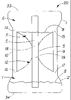
Figure 1 depicts a cross-section of a non-limiting embodiment of a delivery
system 20
comprising at least one container 1 (and 2) comprising at least one wick
opening 18 (and 19), at
least one wick 5, at least one fluid reservoir 6 (and 7), and at least one
volatile material 8. The
delivery system and its components may be made in any suitable size, shape,
configuration, or
type, and from any suitable material. Suitable materials include, but are not
limited to: metal,
glass, natural fiber, ceramic, wood, plastic, and combinations thereof. The
container 1(and 2)
may comprise the exterior surface of the delivery system 20, as such is
subject to visual inspection
as well as being picked up and manipulated by the consumer during use, or it
may be housed in a
shell (not shown). The wick 5 has at least some portion exposed to the
atmosphere. The wick
opening 18 (and 19) may be of any convenient size and shape and may located
anywhere on the
CA 02540924 2006-03-31
WO 2005/032606 PCT/US2004/032332
11
container 1 (and 2). The at least one wick opening 18 (and 19) allows a means
of delivering the
volatile material 8 to the atmosphere via the at least one wick 5 during the
maintenance level
emission and/or boost level emission modes. In certain non-limiting
embodiments, the container
1 (and 2) may be housed in a outer shell (not shown) which is desirably
visually attractive and of
suitable dimensions that it may be left in view in the area of usage for
greatest effectiveness
during evaporative dispensing. When more than one container 1 and 2 is
present, they may be
opposedly-connected and/or fluidly-connected as shown.
In one non-limiting embodiment, the containers 1 and 2 are in fluid-
communication via
an evaporative surface device comprising a wick 5 having at least some
longitudinal exposure to
the atmosphere. The container 1 (and 2) may be attached to any other suitable
component of the
delivery system 20. For instance, containers 1 and 2 may be attached to each
other via the wick 5,
as part of a shell or housing (not shown), or by any other suitable means. The
wick 5 is in fluid
contact with at least some volatile material 8 some of the time. The volatile
material 5 may be
stored in either fluid reservoir 6 or 7. The longitudinal portion of the wick
5 provides enough
exposed wick 5 surface area to allow suitable emission rates of the volatile
material 8 during both
the maintenance level emission and boost level emission modes. Once connected,
containers 1
and 2 and their corresponding fluid reservoirs 6 and 7 may be in fluid-
communication with each
other via the wick 5 or by any other suitable means (e.g. an enclosed channel
or tube). Besides
providing an evaporative surface for emissions, another purpose for connecting
containers 1 and 2
with a wick 5 is to provide a way for excess volatile material 8, which is not
evaporated or
emitted, to be transported from the upper container 1 by gravity for
collection and storage within
the lower container 2 without substantial leaking when the delivery system 20
is inverted by the
consumer.
The wick fitting 3 (and 4) may function as a seal to hold at least some
volatile material 8
in the delivery system 20. The wick fitting 3 (and 4) may be made of any
suitable material in any
suitable size, shape or configuration so as to sealably attach the wick 5
and/or any component to
any component within the delivery system 20. The wick fitting 3 (and 4) may be
attached to any
portion of the delivery system 20 such that it aids in wick 5 loading and
dosing without allowing
substantial leakage of the volatile material 8 from the non-wick portion of
the delivery system 20.
The wick fitting 3 (and 4) may be inserted in the wick opening 18 (and 19),
which is located in
any suitable location on the container 1 (and 2) surface, such that the wick 5
or any other suitable
component (not shown) may pass through the wick opening 18 (and 19) and enter
at least a
portion of the fluid reservoir 6 (and 7). The at least one wick opening 18
(and 19) and wick
CA 02540924 2006-03-31
WO 2005/032606 PCT/US2004/032332
12
fitting 3 (and 4) are dimensioned to both accommodate the wick 5 and any other
component, and
to minimize excess volatile material 8 leakage from the delivery system 20 if
the delivery system
20 is inverted or overturned by the consumer.
The wick 5 may made of any suitable material in any suitable size, shape, or
configuration, such that it functions as an wick to allow emission of the
volatile material 8 by
having at least some portion exposed to the atmosphere. The wick 5 may be
located in any
suitable location within the container 1 (and 2). The wick 5 may be at least
partially located in the
container 1 (and 2), the wick opening 18 (and 19), and/or the wick fitting 3
(and 4), being fluidly
connected to the volatile material 8, which is stored in the fluid reservoir 6
(and 7) of the
container 1 (and 2). The wick 5 may extend inside of the fluid reservoir 6
(and 7) to the container
base 33 (and 34). Conversely, the wick 5 may be of any suitable length which
will maintain the
fluid connection with even a small amount of volatile material 8 in the at
least one fluid reservoir
6 (and 7) while in the maintenance level emission mode throughout the useful
life of the delivery
system 20. There is no particular wick 5 length requirement inside or outside
the container 1 (and
2). The at least one wick 5 may be positioned at any desired internal depth
within the fluid
reservoir 6 (and 7). The at least one wick 5 can optionally occupy the full
internal length of the
both fluid reservoirs 6 and 7 to maximize the emission delivery of the
volatile material 8.
The wick 5 is sealably fastened to the container 1 (and 2) in the location of
the at least
one wick opening 18 (and 19) via the wick fitting 3 (and 4). The wick fitting
3 (and 4) may
sealably hold at least a portion of the wick 5 and other suitable component
passing through the
wick opening 18 (and 19). The wick fitting 3 (and 4) may fit snuggly around
the at least one wick
opening 18 (and 19) and the at least one wick 5, respectively, so as to
prevent unwanted leakage
of the volatile material 8 from the delivery system 20 in storage, during wick
5 loading or dosing
of the wick 5 after inversion, pumping or by spring-action, or if toppled. The
wick fitting 3 (and
4) may be affixed by any means (such as by friction, adhesion, etc) to the
container 1(and 2) so as
to minimize unwanted volatilization of the volatile material 8 especially when
not in use. The
wick fitting 3 (and 4) may be optionally vented (not shown) in any suitable
location so as to aid
loading of the wick 5.
There may be at least one container base 33 (and 34) to aid in stabilizing
and/or hold the
delivery system 20 in the proper configuration, such as, in the upright
position during the
maintenance level emission mode. The delivery system 20 may further comprise
an additional
resealable seal (not shown) for containing the volatile material in the
container 1 (and 2). The
delivery system 20 may further have a package seal (not shown) for covering
the at least one wick
CA 02540924 2006-03-31
WO 2005/032606 PCT/US2004/032332
13
and/or delivery system 20 containing one or more of the volatile materials 8
described above
when desired by the manufacturer or consumer, for instance, when the volatile
material 8 is not
desired to be emitted such as prior to sale or during extended periods away
from the room to be
fragranced.
Fig. 2a depicts a cross-section of another non-limiting embodiment of a
volatile material
delivery system 20 having two containers 1 and 2 which are opposedly-connected
and fluidly-
connected to each other via at least one by-pass tube 9 (and 10) and/or the at
least one wick 5. As
above, the containers 1 and 2, having fluid reservoirs 6 and 7 for containing
at least some volatile
material 8, are fluidly connected via the at least one wick 5 and/or the by-
pass tube 9 (and 10).
The by-pass tube 9 (and 10) may connect to the container 1(and 2) via a by-
pass tube openings
and 17 (14 and 16) having any size, shape, or configuration. The by-pass tube
9 (and 10) may
be formed as an integral component of the container 1 (and 2) or may provided
as a separate
component which is added to the container 1 (and 2). The by-pass tube 9 (and
10) may be made
of any suitable material which is compatible with the container 1(and 2) such
that it may be
suitably sealed or connected to the container 1(and 2) and/or fluid reservoir
6 (and 7) in any
configuration without fluid leakage. The by-pass tube openings 15 and 17 (14
and 16) allow for
direct fluid communication of the volatile material 8 between the fluid
reservoirs 6 and 7 via the
by-pass tube 9 (and 10). The by-pass tube 9 (and 10), as well as the by-pass
tube openings 14 and
16 (15 and 17) may be configured so as to allow for any suitable type of flow
desired. The by-
pass tube 9 (and 10) and/or the by-pass tube openings 14, 15, 16, and/or 17
may be each
structurally modified to provide for open flow, one-way flow, restricted flow,
or combination
thereof, of any fluid that passes through these structures. For example, by-
pass tube openings 14
and 17 may be made with unrestricted flow while by-pass tube openings 15 and
16 may be made
to collect fluid from only one direction or have a reduced flow to provide for
aesthetic benefits,
such as a dripping. This unique flow configuration gives the delivery system
20 the ability to
provide the consumer with unusual visual interests since a modified flow of a
volatile material 8
may attract attention to the delivery system. It is possible for each
container 1 (and 2) to share a
portion of one or more fluid reservoirs 6 (and 7) such that at least some
volatile material 8 may be
present within the delivery system 20 in any particular location at any time.
Such a container 1
(and 2) could, for instance, hold a least some volatile material 8 in both
fluid reservoir 6 and fluid
reservoir 7 immediately after loading or dosing of the wick 5 by inversion,
pumping, or by spring-
action. The volatile material 8 itself may also comprise any suitable adjunct
ingredient in any
suitable amount or in any suitable form. For example, dyes, pigments, and
speckles may provide
CA 02540924 2006-03-31
WO 2005/032606 PCT/US2004/032332
14
additional aesthetic benefits, especially when observed by the consumer during
a modified flow
configuration.
The by-pass tube 9 (and 10) may also serve both as an additional fluid
reservoir for
collecting a certain amount of the volatile material 8, and/or a means to
divert a portion of a
certain volume of volatile material 8 between the opposing fluid reservoirs 6
and 7 after mixing,
pumping or inversion. For example, should the delivery system 20 be toppled
off its base 34 from
the upright vertical position to a horizontal position, the delivery system 20
may be designed to
come to rest in a configuration such that at least one by-pass tube 9 or 10 is
located so that it may
collect at least some volatile material 8 from each fluid reservoir 6 and 7.
In this case, the by-pass
tube 9 or 10 acts as an additional fluid reservoir to decrease the potential
for unwanted spillage
and/or the escape of the volatile material 8 from the delivery system 20.
The wick opening 18 (and 19) may be located anywhere on the exterior surface
of the
container 1 (and 2). For instance, the wick opening 18 (and 19) may be
positioned on the exterior
surface of the container 1 (and 2) such that it lies on a plane parallel to
the plane of the container
base 33 (and 34). A unit dose chamber 11 (and 12) may be located anywhere
within the container
1 (and 2), and is generally within the fluid reservoir 6 (and 7). The unit
does chamber 11 (and 12)
is defined by the interior volume created within the fluid reservoir 6 (and 7)
between the
uppermost region of the at least one wick opening 18 (and 19) and the
lowermost region of the
by-pass tube openings 14 and 15 (16 and 17). The actual volume of unit dose
chamber 11 (and
12) can vary depending on the size of the at least one fluid reservoir 6 and
7, the volume occupied
by the at least one wick 5, and the amount of volatile material 8 delivered to
the at least one unit
dose chamber 11 and 12 upon inversion of the delivery system 20. In certain
non-limiting
embodiments, the consumer can control the volume of volatile material
delivered to the wick 5
via the unit dose chamber 11 (and 12) by adjusting the loading and/or dosing
of the unit dose
volume. This may be accomplished for example, by adjusting the amount of
volatile material 8
pumped, or by manipulating the inversion of the container 1 (and 2), or by any
other suitable
means.
When inverted the delivery system 20 may route excess volatile material 8 from
the upper
fluid reservoir 6 of container 1, which is not collected in the at least one
unit dose chamber 11 or
absorbed by and/or is loaded onto the at least one wick 5, via the by-pass
tubes 9 and 10 via by-
pass tube openings 14 and 15 to the lower fluid reservoir 7 via by-pass tube
openings 16 and 17
for collection and storage in container 2. For example, the unit dose chamber
10 (and 11) may
contain at least some of the volatile material 8 upon inversion of the
delivery system 20 and/or the
CA 02540924 2006-03-31
WO 2005/032606 PCT/US2004/032332
container 1(and 2). When the delivery system 20 and/or the container 1 (and 2)
is inverted and/or
toppled from its upright position, the by-pass tube 9 (and 10) fill with some
of the volatile
material 8 released from the one or more fluid reservoir 6 (and 7), from the
at least one unit dose
chamber 11 9and 12), and/or from the wick 5. .
When the unit dose chamber 11 in the upper fluid reservoir 6 is at least
partially filled,
loaded and/or dosed with at least some of the volatile material 8, the unit
dose chamber 11 will
deliver a controlled volume (e.g. unit dose) of the volatile material 8 to the
wick 5 to provide the
boost level emission to the atmosphere. What excess volatile material 8 that
is not evaporated or
emitted will be transported by the wick 5 and collected in the lower fluid
reservoir 7 without
substantial leakage. The delivery system 20 is also capable of delivering
multiple controlled
volumes and/or unit doses to enable the initiation of multiple boost level
emissions for one or
more of the following purposes: fragrancing, malodor control, insect
repellency, mood setting,
and combinations thereof. The dosing process allows a consumer to deliver a
temporary boost
level emission to a space whenever needed, for example for malodor control.
Dosing of the wick 5 can be performed by any suitable means, for example, by
inversion,
by squeezing a bladder, by non-aerosol pumping, or by any other suitable means
excluding the
use of heat, gas, or electrical current. For example, dosing may occur by
inversion when the
consumer simply turns the delivery system 20 upside down, setting the delivery
system 20 on the
container base 33 (and 34). Thus upon inversion, the volatile material 8 that
was originally stored
in the lower fluid reservoir (6 or 7) is temporarily positioned in the upper
fluid reservoir (6 or 7).
The volatile material 8 begins to inunediately drain from the upper fluid
reservoir (6 or 7) and
pass to the lower fluid reservoir (6 or 7) via gravity through the unit dose
chamber (11 or 12), the
wick 5, and/or the by-pass tube 9 (and 10). Once the volatile material 8 is
collected 'in the dose
chamber 11 (and 12), the boost level emission begins as the volatile material
8 is delivered to the
at least one wick 5 via gravity along the portion of the wick 5 exposed to the
atmosphere. When a
controlled volume of the volatile material 8 is delivered to the one wick 5
via the unit dose
chamber 11 (and 12), the boost level emission may be substantially uniform in
terms of volatility
rates of volatile material 8, over the a portion of the life of the delivery
system 20.
In one non-limiting embodiment, at least some of the unit dose of volatile
material 8 in
the upper fluid reservoir (6 or 7) that passes from the unit dose chamber 11
(and 12) through the
wick opening 18 (and 19) and the wick 5 will be emitted to the atmosphere.
That portion of the
unit dose that is not emitted may be delivered back to the lower fluid
reservoir (6 or 7) via the
wick 5 and/or the wick opening 19 (and 18). Once the unitdose chamber 11 (and
12) in the upper
CA 02540924 2006-03-31
WO 2005/032606 PCT/US2004/032332
16
fluid reservoir (6 or 7) is drained by gravity, the boost level emission
beings to slowly subside
until unit dose either is emitted or passes through to the lower reservoir (6
or 7). When the boost
level emission ceases, the maintenance level emission automatically returns.
In the maintenance
level emission mode, the wick 5 draws volatile material 8 stored in the lower
fluid reservoir (6 or
7) via capillary action to at least some portion of the wick that exposed to
the atmosphere. For
example, the volatile material 8 may be emitted from the full length, or any
portion thereof, of the
exposed longitudinal wick 5 surface between wick openings 18 and 19.
Figure 3a depicts a cross-section of another non-limiting embodiment of a
volatile
material delivery system 20 having two containers 1 and 2 which are opposedly-
connected and
fluidly-connected to each other via by-pass tubes 9 and 10 and/or the wick 5.
In this embodiment,
by-pass tubes 9 and 10 are configured in such a manner as to create a
convenient concave hand
hold for ease of placement of the delivery system 20 and to provide protection
of the wick 5 from
damage if the delivery system 20 is inverted and/or toppled from its upright
position and not
placed on its container base 33 (and 34).
In one non-limiting embodiment, the volume of the unit dose chamber for the
boost level
emission may be defined by the volume of volatile material 8 in the upper
fluid reservoir (6 or 7)
not collected by the by-pass tube 9 (and 10) for channeling back down to the
lower fluid reservoir
(6 or 7). The unit dose chamber walls 23, 24, 25 and 26 may be configured and
located anywhere
within the reservoir 6 (and 7) and/or the container 1 (and 2). For example,
the unit dose chamber
12 may have chamber walls 25 and 26 that are configured below the by-pass tube
openings 16
and 17. The unit dose volume is then collected by the open end 22 of the unit
dose chamber walls
25 and 26. Conversely, other configurations of the chamber walls are also
useful. For example,
the volume of the unit dose collected by the unit dose chamber 11 may be
independent of the
configuration by-pass tube 9 (and 10) and/or the by-pass tube openings 14 and
15. The unit dose
chamber 11 may be located within the fluid reservoir 6 having walls 23 and 24
that extend above
the location of the by-pass tube openings 14 and 15. Here a unit dose volume
of volatile material
8 in the upper reservoir 6 may be collected in the unit dose chamber 11 via
the open end 21 of the
unit dose chamber walls 23 and 24 upon inversion, pumping or by spring-action
of the delivery
system 20.
Fig. 3b depicts a cross-section of another non-limiting embodiment of a
volatile material
delivery system 20 having a gutter assembly. A gutter 138, located near the
wick opening 18 (and
19) on the exterior surface of the container 2, is provided to collect excess
volatile material 8 that
may escape from the wick 5 and/or the wick opening 18 (and 19) after wick 5
loading and/or
CA 02540924 2006-03-31
WO 2005/032606 PCT/US2004/032332
17
toppling of the delivery system 20. Any gutter 138 of any size, shape,
configuration, or material
may be used. In one non-limiting embodiment the gutter is located in the area
in or adjacent to
the location of the wick opening 19. In order to catch or collect excess
volatile material 8 that
may drip out of the opposing wick opening 19 and/or off the wick 5 (such as,
after excessive
loading by inversion, pumping and/or tipping) an absorbent material 139 is
provided. Any
suitable absorbent material 139 may be used in any suitable size, shape, or
configuration. The
absorbent material 139 may be made from any suitable materials that can
substantially absorb
and/or facilitate evaporation of the volatile material 8. The absorbent
material 139 may comprise
any suitable evaporative surface material. For example, suitable absorbent
material 139 may
include paper, plastic, sponge, etc. Excess volatile material 8 that is
collected in the gutter 138
may then be absorbed or reabsorbed by absorbent material 139 and redirected to
the wick 5, the
wick opening 19, or allowed to evaporate directly to the atmosphere.
In certain other non-limiting embodiments, an absorbent material 139 may be
placed in or
near the location of the gutter 138 so as to aid in the collection of excess
volatile material 8 that is
not collected by the lower fluid reservoir 7. For example, the absorbent
material 139 may be
made from wick 5 material in the shape of a thin washer or doughnut that is
located in the gutter
138 and surrounds the at least one wick 5. Fig. 3c depicts a top view of the
gutter assembly
comprising the wick 5, the gutter 138 and the absorbent material 139 in the
shape of a thin washer
or doughnut. It should be noted that the absorbent material 139 does not have
to be in physical
contact with either the wick 5 or the wick opening 19. It may be attached to
any part of the
exterior surface of the delivery system 20 by any suitable means (such as by
friction, adhesion,
fasteners, etc.). In fact, it does not have to be fixedly attached at all
since it can be added or
removed by the consumer as desired. The absorbent material 139 can freely
slide along the
longitudinal axis of the at least one wick 5 coming to rest in the area of the
opposing gutter (not
shown) wherein it can collect any excess volatile material 8 that may be
present in the vicinity of
the opposing wick opening (not shown), for example, during inversion, excess
pumping, or
toppling of the delivery system 20.
Figure 4 depicts another non-limiting embodiment of a volatile material
delivery system
20 having two containers 1 and 2 which are opposedly-connected and fluidly-
connected to each
other via a single by-pass tube 9 and/or the at least one wick 5. The by-pass
tube 9 may take any
suitable size, shape, or configuration and be made of any suitable material.
The by-pass tube 9
may be connected to the container 1 (and 2) by any suitable means at any
suitable location. For
instance, the by-pass tube 9 of similar material as the container 1 (and 2)
may be formed in the
CA 02540924 2006-03-31
WO 2005/032606 PCT/US2004/032332
18
shape of a spiral, sphere, or ellipse and is connected to the reservoir 6 (and
7). The by-pass tube 9
may be part of any component of the delivery system 20. For example, the by-
pass tube 9 may be
integrated in the container 1 (and 2) and/or in the wick 5. The by-pass tube 9
may have one or
more by-pass tube opening 15 (and 17) which allow fluid communication with the
container 1
(and 2) without loss due to leaking or vaporization. For example, the volatile
material 8 may flow
by gravity~ after inversion from the upper reservoir 6 to the lower reservoir
7 via the by-pass tube
9 and/or the at least one wick 5. The by-pass tube opening 15 (and 17) may be
located anywhere
on the surface of the container 1 (and 2) and may be located in such a manner
as to allow the
formation of a unit dose chamber 11 (and 12), located in the interior space of
fluid reservoir 6
(and 7) between the wick opening 18 (and 19) and the by-pass tube opening 15
(and 17), for
delivery of the optionally uniform, temporary boost level emission. The by-
pass tube 9 may
surround the wick 5 so as to protect the wick 5 from physical tampering or
damage if the delivery
system 20 is inverted and/or toppled from its upright position. This
configuration aids in
protecting children from unwanted or direct exposure to the volatile material
8 by discouraging
contact with the wick 5.
Figures 5a, 5b, 5c depict another non-limiting embodiment of a volatile
material delivery
system 20. Fig. 5a depicts the exterior surface of a single integrated
container 1 having one or
more vent openings 35 on the integrated container 1. The one or more vent
openings 35 allow the
volatile material (not shown) to be emitted or delivered from the wick (not
shown) to the
atmosphere of the room or rooms that require treatment. Optionally, an
adjustable vent (not
shown) may be added to the container 1 of the delivery system 20 so that the
width of the one or
more vent openings 35 may be made adjustable and/or closeable. This allows the
maintenance
and boost level emission rates to be controlled by the consumer. The
adjustable vent (not shown)
may be made of any suitable material, be of any suitable size or shape, and be
located anywhere
on or within the delivery system 20. For example, a consumer may open,
partially open, partially
close, or close the one or more vent openings 35 by moving the adjustable vent
(not shown) such
that the desired amount of emission is delivered to the location needing
treatment.
Fig. 5b depicts a non-limiting embodiment of a evaporative surface device 40
having a
wick 5, a wick fitting 3 (and 4), a wick fitting opening 43 (and 44), an
optional wick fitting vent
hole 27 (and 28), and a wick fitting flange 31 (and 32). All components of the
evaporative
surface device 40, may be made of any suitable material, and be of any
suitable size, shape, or
configuration. Each end of the at least one wick 5 may sealably fit into the
wick fitting opening
43 (and 44) of the wick fitting 3 (and 4) so as to allow for fluid
communication between fluid
CA 02540924 2006-03-31
WO 2005/032606 PCT/US2004/032332
19
reservoirs (not shown) via the wick 5 but reduce unwanted leakage of the
volatile material (not
shown) from around the wick fitting-opening 43 (and 44), the wick openings
(not shown), or the
container (not shown) during use or storage.
Fig. 5c depicts a cross-section of another non-limiting embodiment having a
single
integrated container 1 having two fluid reservoirs 6 and 7 which are opposedly-
connected and
fluidly-connected to each other via by-pass tubes 9 and 10 and/or the at least
one wick 5. In this
embodiment, the by-pass tube 9 (and 10) is configured within the interior of
the single integrated
container 1 in such a manner as to create a convenient concave hand hold for
ease of placement of
the delivery system 20 and to provide protection of the wick 5 from damage
during inversion
and/or if the delivery system 20 toppled from its upright position. The unit
dose chamber 11 (and
12) is located within the fluid reservoir 6 (and 7) of the single integrated
container 1. The one
unit dose chamber 11 (and 12) can have walls 23 and 24 (25 and 26) in the
shape of a cup with an
open end 21 (and 22) for collection of the volatile material 8 when the
delivery system 20 is
inverted. The unit dose chamber 11 (and 12) may contain at least some of the
volatile material 8
at anytime, especially immediately after inversion. The volatile material 8
may flow by gravity or
by non-aerosol pump (not shown) via the by-pass tube 9 (and 10) and/or the
wick 5 to the
opposing fluid reservoir (6 or 7). The at least one wick opening 18 (and 19)
allows penetration of
the wick 5 to the fluid reservoir 6 (and 7). The unit dose chamber walls 23
and 24 (25 and 26)
may extend above the by-pass tube openings 14 and 15 (16 and 17) inside the at
least one fluid
reservoir 6 (and 7) when in the upright position or they may be at or below
these openings
depending on the at least one wick 5 loading requirements. The wick fitting
bracket 36 (and 37)
may be located in any suitable location on the integrated container 1 so as to
accept and provide
for a tight seal with the wick fitting 3 (and 4) and the wick 5. The wick
fitting 3 (and 4) may be
configured to tightly hold the wick 5 as it is placed in the wick fitting
bracket 36 (and 37), which
may be made to sealably enclose the wick fitting 3 (and 4) and/or the wick 5
to minimize leakage
of the volatile material 8 at or from either or both the junctions of the wick
fitting 3 (and 4) and
the wick 5 or the wick fitting 3 (and 4) and the wick fitting bracket 36 (and
37).
Fig. 6 depicts a cross-section of another non-limiting embodiment of a
volatile material
delivery system 20 having two containers 1 and 2 which are opposedly-connected
and fluidly-
connected to each other via the at least one by-pass tube 9, and/or the at
least one wick 5. For
example, the by-pass tube 9 may be incorporated within the wick 5 itself. It
can be located near
but not in physical contact with the wick 5 or it can actually be in physical
contact the wick 5.
One or more by-pass tube opening 15 (and 17) may be located anywhere within
the wick 5, the
CA 02540924 2006-03-31
WO 2005/032606 PCT/US2004/032332
reservoir 6 (and 7), and/or the container 1 (and 2) of the delivery system 20.
For example, the by-
pass tube 9 can enter the same wick opening 18 (and 19) as the wick 5 but can
be made longer
and be positioned away from the wick 5 so as to act as an alternative fluid
reservoir for collecting
volatile material 8 when and if the delivery system 20 is inverted and/or
toppled. In another
example, the by-pass tube opening 15 (and 17) may be integrated within the
wick opening 18 (and
19) such that both the by-pass tube 9 and the wick 5 pass through the same
opening. In this case,
only one seal (not shown) may be needed to prevent excess volatile material 8
from escaping the
delivery system 20 during the boost level emission mode. This will reduce the
costs of
manufacture and reduce the potential for seal failure or leakage. The by-pass
tube 9 also may be
made of wick 5 material by simply creating a cavity within the wick 5 itself.
There can be more
than one by-pass tube 9 and/or wick opening 15 (and 17) in the same reservoir
6 (and 7) and/or in
the same wick 5.
Fig. 7a depicts the cross-section of another non-limiting embodiment of a
delivery system
20 in the maintenance level emission mode. The delivery system 20 has two
reservoirs 78 and 79,
two by-pass tubes 9 and 10, one wick 5, and at least one multi-phase volatile
material comprised
of two or more separate and distinct phases 61 and 83. Any suitable multi-
phase volatile material
in any suitable amount, density and/or viscosity may be used. During the
maintenance level
emission mode, the multi-phase volatile material is stored in the lower fluid
reservoir 79. The
separate and distinct phases 61 and 83 may be delivered to the atmosphere via
capillary action
from the fluid reservoir 79 to the at least one wick 5 in any suitable order
or sequence. For
example, the wick 5 may draw and deliver both phases in equal amounts from the
reservoir 79
(and 80) to the atmosphere; and preferentially deliver phase 61 quicker than
phase 83, and vice
versa. Any other method that causes the wick 5 to preferentially draw and
deliver fluid from one
of the desired phases at a rate greater than that of the other at rest or
equilibrium may be used.
For example, the length of the at least one wick 5 may be configured or height
positioned within
the fluid reservoir 80 such that it preferentially draws phase 61 during the
maintenance level
emission while at the same time not drawing on phase 83. Other means of
providing differential
uptake by the wick include, but are not limited to: providing different wick
material types and/or
designs, and adjusting the chemical properties of the different phases in the
multi-phase volatile
composition to modify uptake on the wick 5.
Fig. 7b depicts the delivery system 20 in the boost level emission mode. When
a boost
level emission is desired, the consumer inverts the delivery system 20. Upon
inversion, the lower
fluid reservoir 79 (of Fig. 7a) becomes the upper fluid reservoir 79 of Fig.
7b. Whereupon, at
CA 02540924 2006-03-31
WO 2005/032606 PCT/US2004/032332
21
least some of the multi-phase volatile material is collected in the unit dose
chamber 80 while the
excess multi-phase volatile material begins to drain to the lower fluid
reservoir 78 via inlet
openings 16 and 17 and by-pass tubes 9 and 10. The location of the at least
one by-pass tube
openings 16 and 17 may allow the consumer to fill the unit dose chamber 80
and/or the at least
one wick 5 with a desired fluid phase.
The character, as well as, the intensity of the multi-phase volatile material
perceived by
the consumer during the boost level emission may change upon mixing and/or
displacement of the
separate phases 61 and 83 of the multi-phase composition being collected in
the unit dose
chamber 80. Any suitable physical property or characteristic of the multi-
phase volatile material
78 may be used to separate and preferentially load the at least one wick 5
with the desired phase.
The density of the at least two separate and distinct phases of the multi-
phase volatile
material may control how and when a particular volatile material phase is
delivered to the wick 5.
For example, though a less dense phase 61 may enter the by-pass tubes 9 and 10
and flow faster
upon mixing after inversion than a more dense phase 83, the more dense phase
83 may actually
displace some or all of the less dense phase 61 in the unit dose chamber 80
given the proper
configuration and/or conditions. When a portion of the more dense phase 83
displaces a portion
of the less dense phase 61 in the unit dose chamber 80, the displaced less
dense phase 61 may
then be drained back to the lower fluid reservoir 78. During the boost level
emission mode, the
more dense phase 83 is preferentially delivered to the wick 5 and emitted to
the atmosphere over
the less dense phase 61. Thus, the same multi-phase volatile material at the
maintenance level
emission mode may exhibit a different character and/or intensity during the
boost level emission
mode.
Similarly, the viscosity of the at least two separate and distinct phases of
the multi-phase,
volatile material (not shown) may control how and when a particular volatile
material phase is
delivered to the wick. For example, at equilibrium during the maintenance
level emission, the
wick may be located at a specific height or in a specific position in the
lower fluid reservoir so as
to draw from the more viscous phase of the two or more volatile materials.
Upon mixing during
the boost level emission, the lower fluid reservoir becomes the upper fluid
reservoir. Since the
less viscous phase may flow faster than the more viscous volatile material,
the unit dose chamber
may be first filled with the less viscous phase. The more viscous volatile
material, being slightly
less or of similar density with the less viscous phase, is directed to the by-
pass tubes and collected
by the lower fluid reservoir via gravity. Thus, during the boost level
emission mode, the less
CA 02540924 2006-03-31
WO 2005/032606 PCT/US2004/032332
22
viscous volatile material is preferentially delivered to the wick and emitted
to the atmosphere over
the more viscous phase.
Fig. 8a depicts the cross-section of another non-limiting embodiment of the
volatile
material delivery system 20 having at least one secondary wick 38. The at
least one secondary
wick 38 may be loaded with volatile material 8 at any time, for example, upon
inversion of the
delivery system 20 or by non-aerosol pump to deliver a boost level emission.
The secondary wick
38 may aid in the delivery of an increased intensity of volatile material 8 to
the atmosphere by
increasing the evaporative surface area during the boost level emission mode.
The secondary
wick 38 made of any suitable material in any suitable size, shape, or
configuration. For example,
the secondary wick 38 may in the shape of a flat washer, hollow ring, or
doughnut, extending at
least partially within the at least one fluid reservoir 6 (and 7) such as,
just beyond the junction of
the at least one wick opening 18 and 19 as shown. The secondary wick 38 may
also be extended
to any position within the fluid reservoir 6 (and 7), such as, to the full
length of the interior fluid
reservoir 6 (and 7) cavity, perhaps even touching the interior surface of the
container base 33 (and
34). In this example, the secondary wick 38 may be in physical contact with
the primary wick 5.
Fig. 8b depicts the cross-section of another non-limiting embodiment of the
volatile
material delivery system 20 having at least one secondary wick 39 not in
physical contact with the
primary wick 5.
Fig. 8c depicts the cross-section of another non-limiting embodiment of a
multiple
delivery system 100 having a plurality of individual delivery systems. For
example, the delivery
system 100 may comprise of a plurality of separate containers 101, 102, 103
and 104 in any
configuration, not all of which are physically-connected, opposedly-connected,
or fluidly-
connected. Containers 101 and 102 may be opposedly-connected, and/or fluidly-
connected, but
not necessarily physically-connected to containers 103 and 104, yet all may be
housed in a single
delivery system 100 or housing (not shown). Each pair of containers 101 and
102, and 103 and
104 may contain at least one reservoir or a pair of reservoirs 113 and 116,
and 114 and 115, and
respectively. Each pair of reservoirs 113 and 116, and 114 and 115 may have at
least one by-pass
tube 107 (and 108) and corresponding by-pass tube openings 109 and 111, (110
and 112) that
fluidly-connects the opposing reservoir pairs as described above. In this
embodiment, different
volatile materials may be provided in each of the fluid reservoir pairs. For
example, volatile
material 117 may be provided in reservoir pair 113 and 116, while volatile
material 118 may be
provided in reservoir pair 114 and 115.
CA 02540924 2006-03-31
WO 2005/032606 PCT/US2004/032332
23
The position, location, size, shape, and configuration of the individual wick
105 (and
106) may vary according to the requirements of each individual delivery system
housed in the
multiple delivery system 100. For example, wick 105 may be positioned in
reservoir 116 so that
the wick 105 extends the full length of the interior fluid reservoir 116
cavity of container 101
while the wick 105 extends only partially within the interior fluid reservoir
113 cavity of
container 102. Similarly, wick 106 may be positioned in reservoir 114 so that
the wick 106
extends the full length of the interior fluid reservoir 114 cavity of
container 103 while the wick
106 extends only partially within the interior fluid reservoir 115 cavity of
container 104.
In this configuration, a different fragrance may be emitted from each
individual delivery
system during the two separate maintenance level emission modes. In the first
maintenance level
emission mode (A), wick 105 is immersed in volatile material 118 while at the
same time wick
106 is non-immersed in volatile material 117. Thus, only wick 105 is active,
emitting volatile
material 118 via capillary action. When the boost level emission mode is
desired, the multiple
delivery system 100 is inverted. The lower fluid reservoirs 115 and 116 become
the upper fluid
reservoirs. In the boost level emission mode, wicks 105 and 106 are
individually loaded and/or
dosed with the volatile material 118 and 117, respectively. When the boost
level emission mode
is completed and the volatile material 117 (and 118) drains to their
respective lower reservoir
pairs 114 (and 113) via either the by-pass tube 107 (and 108) or wick 105 (and
106), the second
maintenance level emission mode automatically begins.
In the second maintenance level emission mode (B), wick 106 is immersed in
volatile
material 117 while at the same time wick 105 is non-immersed in volatile
material 118. Thus,
only wick 106 is active, emitting volatile material 117 via capillary action.
Thus, the character of
the boost level emission is different than both maintenance level emissions
(A) and (B) which
may be in turn be different in character from themselves.
Fig. 9a, 9b, 9c, and 9d depict the cross-sections other non-limiting
embodiments having a
single container 1, at least one fluid reservoir 6 and at least one dosing
tube 45 in the maintenance
level emission mode. When the boost level emission mode is desired, the
inversion of the
delivery system 20 in Fig. 9a is required to load and/or doses the wick 5 with
a volatile material 8.
The wick 5 is at least partially located inside the at least one fluid
reservoir 6 and is fluidly-
connected to at least some of the volatile material 8 that is stored in the at
least one fluid reservoir
6. Upon inversion, the dosing tube inlet opening 49 collects the volatile
material 8, located within
the fluid reservoir 6, in the dosing tube 45, which becomes at least partially
filled with the volatile
material 8. When the delivery system 20 is returned to the upright position by
being placed back
CA 02540924 2006-03-31
WO 2005/032606 PCT/US2004/032332
24
on its container base 34, at least some portion of the volatile material 8 is
collected by the dosing
tube 45. The collected portion of volatile material 8 then flows by gravity to
the wick 5 via the
dosing tube. outlet opening 51 which is physically and/or fluidly-connected to
the wick dosing
chamber 54 which in turn is physically and/or fluidly-connected to the wick 5
and/or the at least
one secondary wick 38. The wick dosing chamber 54 allows the volatile material
8 to wet the
wick 5 and the secondary wick 38 with at least some of the volatile material 8
collected in the
dosing tube 45 after inversion for delivery of the boost level emission. It
should be noted that
delivery of the maintenance level emission in this embodiment requires no
mechanical action,
such as inversion. The capillary loading of the wick 5 automatically returns
after inversion. The
capillary action automatically may continue until the delivery system 20 is
substantially exhausted
of the volatile material 8 by the emission processes.
Like the embodiment of Fig. 9a, the embodiment of Figures 9b and 9c also
require no
mechanical step to deliver the maintenance level emission. However, unlike the
previous
embodiment, the boost level emission is accomplished by loading the wick 5
and/or secondary
wick 38 (and 39) with volatile material 8 via a squeezable bladder 47 or non-
aerosol pump 48.
Fig. 9b uses the squeezable bladder 47, which draws at least some volatile
material 8 from the
fluid reservoir 6 of container 1 via the dosing tube inlet opening 49. The
volatile material 8 is
collected in the dosing tube 45 and is collected in the bladder 47 via the
bladder inlet opening 52
and is discharged to the dosing tube 46 via the bladder outlet opening 53 when
the bladder is
squeezed. The wick 5 and the optional secondary wick material (not shown) may
be loaded or
dosed according to the method described above in Fig. 9a.
Like the embodiment of Fig. 9b,' the embodiment of Fig. 9c uses the same
delivery
concept except the squeezable bladder 47 is replaced with a non-aerosol hand
pump 48. The non-
aerosol hand pump 48, having pump inlet opening 56 and pump outlet opening 55,
may be of any
suitable type, size, shape, and/or dimension having a suitable pump head such
that at least some
volatile material 8 is delivered to the wick 5 and/or the secondary wick 38
and 39 when the non-
aerosol hand pump is used with minimal mechanical effort. There is no sprayer
attached to any
pump or squeezable bladder device.
Fig. 9d depicts the cross-section another non-limiting embodiment of a
delivery system
20 having two separate containers 1 and 50. The wick 5 is fluidly-connected to
the volatile
material 8 stored in the fluid reservoir 6 via the sealable wick opening 18. A
maintenance level
emission is provided by capillary action of the volatile material 8 via the at
least one wick 5 to the
atmosphere. The wick 5 may be of any suitable size or length and may extend
within the
CA 02540924 2006-03-31
WO 2005/032606 PCT/US2004/032332
reservoir 6 to the interior surface of the container base 34. Container 50 is
fluidly connected to
container 1 via a dosing tube 46. Container 50 may comprise a dosing funnel
71, a dosing
diffuser 72, a collection base 73, a secondary fluid reservoir 57, and a
secondary wick 38. When
a boost level emission is desired, the volatile material 8 of container 1 may
be delivered to the
secondary wick 38 of container 50 by any suitable means. The volatile material
8 is delivered to
the dosing tube 46 via the dosing tube inlet opening 49. The volatile material
8 enters container
50 via the dosing tube outlet opening 51 where it is collected by an dosing
funnel 71, which
directs the volatile material 8 to the dosing diffuser 72, which delivers the
volatile material 8 to
the secondary wick 38. The secondary wick 38 is fluidly connected to the
dosing diffuser 72 and
the dosing funnel 71. The secondary wick 38 may also be fixedly connected to
the dosing
diffuser 72 and the container base 73 via any suitable connection.
The secondary wick 38 may be any suitable size or shape. For example, the
secondary
wick may be in the shape of a hollow cup, sphere or ring wherein the volatile
material 8 flows by
gravity from the dosing diffuser 72 through the secondary wick 38 to the
container base 73. The
secondary wick 38 may comprise from any suitable surface area. For example, a
suitable surface
area may range from about 1 to about 100 times, or from about 1 to about 50
times, or from about
1 to about 20 times, or from about 1 to about 5 times more surface area than
the at least one wick
5. The increase in wick surface area may be provided by any suitable means,
such as by varying
the pore size of the wick material or by pleating or folding the wick
material.
Like the embodiments in Figs. 9a, the embodiment of Fig 9d may initiate the
boost level
emission by inversion (or by any other suitable means) of container 1 such
that volatile material 8
is delivered to the secondary wick 38 for boost level emission. Excess
volatile material 8 that is
not collected onto the secondary wick 38 after being delivered via the dosing
diffuser 72 may be
collected in the secondary fluid reservoir 57, which is fluidly connected to
the secondary wick 38.
The secondary wick 38 may also be a porous solid, having an optional secondary
fluid reservoir
57. The porous solid may absorb excess volatile material 8 not immediately
emitted from the
secondary wick 38 itself. The boost level emission will last until all of the
volatile material 8
evaporates. For example, all the volatile material 8 that is loaded onto the
secondary wick 38 or
that is stored in the secondary fluid reservoir 57 will be delivered to the
atmosphere via
evaporation during the boost level emission.
Figs. 10a and 10b depict the cross-sections another non-limiting embodiment of
a
delivery system 120 having an adjustable, high-surface area wick 58 that can
deliver more or less
volatile material 8 to the atmosphere depending on the amount of surface area
exposed to the
CA 02540924 2006-03-31
WO 2005/032606 PCT/US2004/032332
26
atmosphere. Fig. 10a represents the delivery system 120 at the equilibrium
state wherein the least
amount of surface area of the wick 58 is exposed to the atmosphere. The spring
75 is
uncompressed in its equilibrium state. In the folded position at equilibrium,
the wick 58 provides
the maintenance level emission.
In certain embodiments, the delivery system 120 comprises a wick spring
assembly
comprising an adjustable, high-surface area wick 58, a wick retraining ring
60, a spring 75, an
optional damping device (not shown), a spring restraining device (not shown),
optionally, a
perforated protective shell 121, and at least one lever 122 for compressing
the spring 75 via the
wick restraining ring 60. The perforated protective shell 121 may be made of
any suitable
material in any size, shape, or configuration so as to allow for unrestricted
emission flow of
volatile material via the perforations (not shown), which may be any suitable
size, shape or
configuration. For example, the perforations (not shown) may be a plurality of
slots. The
perforated protective shell 121 may provide for a vertical slot 123 that
allows the lever 122, which
is attached to the wick restraining ring 60, to travel the full length
required for spring 75
compression. The wick spring assembly allows the consumer to configure or
adjust the exposed
surface areas of wick 58 in order to vary the intensity of the boost level
emission. While using the
lever 122 to compress the spring 75, the consumer may deliver the boost level
emission without
having to invert the delivery system 120.
Fig. 10b represents the delivery system 120 in the maximum boost level mode.
Here the
greatest amount of surface area of the wick 58 is exposed to the atmosphere.
The spring 75 is
fully compressed. The wick 58 may be made of any suitable material in any
suitable shape or size
such that when it is unrestrained, it opens or unfolds to expose its greatest
surface areas to the
atmosphere. As the spring 75 gradually returns to its equilibrium length, the
surface area of the
wick is reduced by the wick restraining ring 60. The optional spring damping
device (not shown)
will allow variable boost level emission durations to be provided. When the
wick spring to its
equilibrium state, the boost level emission mode ceases and the maintenance
level emission mode
automatically returns. Thus, the duration and intensity of the boost level
emission may be
controlled by the consumer by simply depressing the lever 122 to the desired
position.
Fig. 11 depicts the cross-section of another non-limiting embodiment of a
delivery system
20 having a stability cradle 62. The stability cradle 62 may be made of any
suitable material
having any suitable size, shape, or configuration, such that the delivery
system 20 is at least
partially stabilized in a suitable dispensing position (for example, an
upright positions) once
placed in the stability cradle 62. The upright position in this case refers to
any inclination greater
CA 02540924 2006-03-31
WO 2005/032606 PCT/US2004/032332
27
than 45 degrees from vertical in any direction. For example, the stability
cradle 62 made be made
of wood, metal, plastic and/or glass and may optionally have a recessed area
63 which when in
contact with the at least one container base 34 adds at least some stability
to the delivery system
20. The stability cradle 62 allows consumers the convenience of identifying a
setting for the
delivery system 20 in any room or location needing treatment (for example,
living room, kitchen,
bathroom, garage, backyard, etc.). The stability cradle 62 may allow for
decorative items to be
placed onto the structure in order to allow the consumer to personalize the
delivery system 20.
For example, a colored veneer may be selected having many different decorative
colors available
for color coordination. The decorative items may be attached anywhere on the
stability cradle 62
and/or delivery system 20 by any fastening means, such as fasteners,
adhesives, lock and key
devices, etc.
Fig. 12 depicts the cross-section of another non-limiting embodiment of a
delivery system
20 having at least one ballast 63 which may be made of any suitable material
in any size, shape,
or configuration, so as to provide at least some stability against overturning
once the delivery
system 20 is overturned by touching, shaking, unleveling toppling, or
otherwise. Suitable forms
of suitable ballast materials include, but are not limited to: solids,
liquids, gels, powders, granules,
and combinations thereof. For example, the ballast 63 may comprise any
suitable material having
any suitable weight in order to reduce overturning of the delivery system 20.
The ballast 63 may
be attached to the delivery system 20 and/or the container 1(and 2) in any
suitable manner (for
example, fixed, non-fixed, etc). The ballast 63 may be removably attached to
allow adjustment on
the delivery system 20. Thus, the ballast 63 may be positioned and/or
repositioned on the
container 1 (and 2) in any suitable configuration and by any suitable means.
For example, the
consumer may attach the ballast 63 to the lower container 2 after inversion.
Alternatively, the
manufacturer may attach the ballast 63 so that it may automatically be
repositioned from the
upper container 1 to the lower container 2 by the action of gravity when the
at delivery system 20
is inverted.
The ballast 63 may be connected to the at least one container via any suitable
mechanism,
for example a sliding mechanism. The ballast 64 may freely move along a
longitudinal axis of the
delivery system 20 by gravity, for example, by sliding along the by-pass tube
9 (and 10) via an
attachment device 65, such as a ring. Alternatively, the ballast 64 may be
physically relocated,
without sliding, for example, by clipping the ballast 64 to any portion of the
delivery system 20,
such as to the lower container base 34 or to the by-pass tube 9 (and 10),
before, during, or after
the inversion process. A suitable attachment device 65 can be made of any
suitable material in
CA 02540924 2006-03-31
WO 2005/032606 PCT/US2004/032332
28
any suitable size, shape, or configuration. For example, the attachment device
65 may be a clamp,
clip, ring, string, tie, adhesive material, friction fitting, magnet, and
combinations thereof. The at
least one ballast 63 may also be attached and/or connected to the at least one
container 1(and 2)
in a fixed position. In one non-limiting embodiment, the ballast (not shown)
may be in the form
of sand or a ball bearing that is housed in a component of the delivery system
20.
Fig. 13a depicts a perspective view of another non-limiting embodiment of a
delivery
system 20 having four by-pass tubes 65, 66, 67, and 68 and at least one wick
5. When overturned
over, the by-pass tubes 65, 66, 67, and 68 may act as secondary fluid
reservoirs to collect some of
the volatile material (not shown) that was stored in either fluid reservoir
(not shown) and thereby
minimize leakage from the delivery system 20. Fig. 13b shows the top view of
the delivery
system 20 of Fig. 13a. This configuration aids in stabilizing the delivery
system 20 after toppling
from the upright position. Fig. 13c shows the cross-section view (A-A) through
the by-pass tubes
66 and 68.
Fig. 14 depicts a perspective view of another non-limiting embodiment of a
delivery
system 20 having an external frame 69 having at least one ballast 70. The
external frame 69 may
be made of any suitable material and configured in any suitable size or shape.
The external frame
69 may be removeably attached to the delivery system 20 by any suitable means.
The ballast 70
may also be removably attached to the external frame 69. The delivery system
20 may be easily
removed from the external frame 69 and inverted by the consumer before
reattaching.
Alternatively, the delivery system 20 may be inverted in place. For example,
the external frame
69 may provide a means to invert the delivery system 20 by providing a
pivoting arm (not shown)
which allows the consumer to simply invert the delivery system 20 by pushing
on the container 1
(and 2). The ballast 70 may be removed after the delivery system 20 and
reattached to the
external frame 69 as needed, for example, for cleaning.
Fig. 15a depicts a cross-section of a delivery system 20 comprising another
wick spring
assembly mechanism. The wick spring assembly comprises at least one
retractable wick 86, at
least one spring 87, at least one spring adjuster 88, an optional damping
device (not shown), and a
spring restraining device (not shown). Like the embodiment of Fig. 10a, the
maintenance level
emission mode occurs at the equilibrium state where the least amount of
surface area of the
retractable wick 86 is exposed to the atmosphere. At equilibrium, the
retractable wick 86 is
immersed in the volatile material 8 contained in the fluid reservoir 6 of the
container 1. In this
case, the wick spring assembly 75 would be compressed in the equilibrium
state.
CA 02540924 2006-03-31
WO 2005/032606 PCT/US2004/032332
29
When a boost level emission is desired, more surface area of the retractable
wick 86 is
exposed to the atmosphere. For example, the consumer may increase the wick
surface area by
pulling up on the spring adjuster 88 to the desired length and thereby
exposing more retractable
wick 86 surface area to the atmosphere than is exposed at equilibrium. When
the retractable wick
86 is fully extended, the wick spring 75 is uncompressed. The volatile
material 8 emission rate
increases as a function of the amount of wick surface area exposed. The more
surface area
exposed, the higher the boost level emission rate. Thus, the consumer has the
ability to control
perceived intensity levels during the boost level emission mode by varying the
amount of
retractable wick 86 surface area exposed. As the wick spring assembly 75
gradually compresses
back to the equilibrium state, the retractable wick 86 is returned to the
fluid reservoir 6 of
container 1 where it is again immersed in and reloaded with the volatile
material 8. Thus, the
boost level emission may be uniformly delivered, being repeated as many times
as necessary by
the consumer until the volatile material 8 is exhausted.
Any other suitable means of increasing the intensity of the boost level
emission is also
useful. For example, in certain other embodiments, the volatile material in
the delivery system
may be in the form of a gel or liquid gel (not shown). In such a case, the
wick may be modified to
facilitate the loading of the volatile gel composition onto the wick, the
spring itself, and/or onto a
suitable delivery device such as, paddles, which can be attached onto or
adjacent to the wick
spring. The gel-laden wick spring itself and/or the delivery device can
provide the means to
deliver boost level emission. At equilibrium, evaporation of the volatile gel
composition from off
the top layer surface of the wick and/or volatile gel material would provide
the maintenance level
emission mode. Conversely, as the gel-laden wick spring is extended away from
the container in
the uncompressed mode (similar to the embodiment of Fig. 15b), more surface
area evaporation of
the volatile gel material would occur. As the wick spring gradually returns to
equilibrium, the
boost level emission would automatically cease while the maintenance level
emission would
automatically return.
In other alternative embodiments, the delivery system can comprise a kit
containing a
bundle or packs of one or more volatile materials. Any of the foregoing
embodiments may be
used in supplying consumers with their initial product(s), as well as with
refills for the same. In
certain non-limiting embodiments, the delivery system may comprise supplying
consumers with a
choice of different types of volatile materials (for example, a fragrance
composition, a malodor
reducing composition, an insecticide, a mood enhancer composition, or
combinations thereof)
other than, or in addition to, the volatile materials sold in the initial
product(s).
CA 02540924 2006-03-31
WO 2005/032606 PCT/US2004/032332
The disclosure of all patents, patent applications (and any patents which
issue thereon, as
well as any corresponding published foreign patent applications), and
publications mentioned
throughout this description are hereby incorporated by reference herein. It is
expressly not
admitted, however, that any of the documents incorporated by reference herein
teach or disclose
the present invention.
It should be understood that every maximum numerical limitation given
throughout this
specification would include every lower numerical limitation, as if such lower
numerical
limitations were expressly written herein. Every minimum numerical limitation
given throughout
this specification will include every higher numerical limitation, as if such
higher numerical
limitations were expressly written herein. Every numerical range given
throughout this
specification will include every narrower numerical range that falls within
such broader numerical
range, as if such narrower numerical ranges were all expressly written herein.
While particular embodiments of the subject invention have been described, it
will be
obvious to those skilled in the art that various changes and modifications of
the subject invention
can be made without departing from the spirit and scope of the invention. In
addition, while the
present invention has been described in connection with certain specific
embodiments thereof, it
is to be understood that this is by way of illustration and not by way of
limitation and the scope of
the invention is defined by the appended claims which should be construed as
broadly as the prior
art will permit.