Note : Les descriptions sont présentées dans la langue officielle dans laquelle elles ont été soumises.
CA 02541062 2006-03-31
WO 2005/033441 PCT/SE2004/001420
1
APPARATUS FOR FACILITATING NEW CONSTRUCTION AND THE
INTERNAL INSPECTION AND REPAIR OF LARGE VESSELS,
SUCH AS RECOVERY BOILERS AND TANKS
Field of the Invention
The present invention relates to an apparatus for
facilitating new construction and internal inspection
and repair of large vessels, such as recovery boilers
and tanks. The apparatus comprises a platform which is
vertically adjustably suspended by means of suspension
cords hanging down from a roof of the vessel, the plat-
form being built from at least two parallel spaced-apart
girders, to which the suspension cords are attached, and
at least one plank being arranged perpendicular to the
girders and interconnecting the same, the plank resting
on the girders and at least partly covering the same.
Background Art
When large vessels, such as recovery boilers and
tanks, are to be built and internally inspected and pos-
sibly repaired, the large dimensions thereof always make
it necessary to use some kind of scaffold or platform,
from which the work can be performed in a safe way. Then
there is frequently the problem that the parts included
in this scaffold or platform must be inserted through
relatively small manholes in the walls or roof of the
vessel. Another problem is that the above-mentioned large
dimensions require the use of a large number of scaffold
or platform parts so that all parts of the vessel can be
reached. A further problem is that the parts inside the
vessel must frequently be mounted under difficult cir-
cumstances, such as high heat inside a boiler. Finally,
especially in boilers, there is also the problem that on
the one hand some parts of the vessel can be difficult to
reach because of what is referred to as a nose which is
CA 02541062 2006-03-31
WO 2005/033441 PCT/SE2004/001420
2
to be found in certain boilers, i.e. a projecting portion
on one of the side walls of the boiler, and on the other
hand that it may be necessary to inspect or repair super-
heaters which are suspended from the roof of the boiler
and which between them form narrow passages.
US-A-5,007,501 discloses an apparatus, which is
especially intended for the boiler in a thermal power
station and which eliminates some of the problems occur-
ring in the same. More specifically, a smaller number of
parts are required for the known apparatus than for a
traditional scaffold which is erected standing on the
bottom of the large vessel. However, the mounting of the
prior-art apparatus is still based on initial mounting
from the bottom of the large vessel, still comprises a
large number of parts that must be assembled, and does
not solve all the problems of accessibility in a satis-
factory manner.
Japanese Published Application JP-A-2000-054618
discloses an apparatus as stated by way of introduction,
which eliminates at least one of the problems with the
solution according to US-A-5,007,501. The apparatus
according to the Japanese publication thus solves the
problem with the initial mounting from the bottom of the
vessel, but at the same time its applicability is limit-
ed significantly by the fact that the footboard, which is
formed of said at least one plank, extends only perpendi-
cular to the girders. This greatly limits the applicabi-
lity and safety of the apparatus when, because of an
obstacle, a gap must be left between two neighbouring
planks.
Object of the Invention
In view hereof, the object of the invention is to
improve the known apparatus according to JP-A-2000-054618
in such a manner that the remaining problems with this
apparatus are eliminated and moreover a considerably more
flexible and safer apparatus is provided, which for new
CA 02541062 2006-03-31
WO 2005/033441 PCT/SE2004/001420
3
construction, inspection and repair is universally
applicable to all types of large vessels.
Summary of the Invention
According to the invention, this is achieved by an
apparatus of the type mentioned by way of introduction,
said apparatus being characterised in that the girders
are individually vertically adjustable first lattice
girders, to which the suspension cords are attached and
which have flat upper sides forming a footboard.
By the apparatus according to the invention compris-
ing individually vertically adjustable lattice girders,
which have a built-in plank for walking, there is provid-
ed, in contrast to JP-A-2000-054618, a safe floor surface
also along the girders. The lattice girders are insert-
able in a hanging manner through manholes in the vessel
at any level without necessitating setting foot upon the
bottom of the vessel. Said at least one plank is then
arrangeable in any position between two parallel suspend-
ed lattice girders. It will thus be possible to inspect,
from the thus provided platform, for instance all walls
of a recovery boiler, i.e. also those above the above-
mentioned nose, or the superheaters of this boiler all
the way up to the roof of the boiler. Owing to the over-
length of the plank resting on the girders (it is longer
than the normal distance between two juxtaposed girders
suspended at the same level), it will be possible within
reasonable limits on the one hand to individually lower
and raise the lattice girders involved and, on the other
hand, to follow the contour of the superheaters which in
course of time will frequently be very irregular owing to
the high temperatures occurring in the operation of the
boiler.
The girders of the apparatus are preferably rectan-
gular in cross-section, and the suspension cords are
suitably attached to them by enclosing holders which
enclose the respective girders and have an upper side
CA 02541062 2006-03-31
WO 2005/033441 PCT/SE2004/001420
4
which has a centrally arranged fastening means for each
suspension cord. The advantages of girders that are rec-
tangular in cross-section are that they have an excellent
load-carrying capacity, that, if desired, they can easily
be connected perpendicular to a corresponding girder of
rectangular cross-section, and that outside the vessel
they are stackable in an advantageous way.
Said enclosing holders each preferably consist of
two essentially C-shaped halves, with the C openings fac-
ing one another, said halves having at their upper and
lower ends lugs, through which locking cotter pins are
movable for locking said halves together. Thus designed
holders protect in an advantageous manner the girder con-
struction from being damaged by squeezing especially on
the sides and ensure, by extending under the girder, that
the entire load-carrying capacity of the girder construc-
tion can be utilised.
Preferably, the lugs of the enclosing holders form
at the upper ends said fastening means for the suspension
cords. It will thus in an advantageous manner be possible
to use the same locking cotter pin both for locking toge-
ther the halves of the enclosing holders and for attach-
ing a suspension cord.
The halves of the enclosing holders are suitably
made of a band material of steel bent to the cross-
sectional contour of the girders. Steel has the advantage
that it is very stable in shape and has great tensile
strength and that it is easy to weld, which considerably
facilitates the attachment of the lugs for the locking
cotter pins.
The apparatus according to the invention may, if
desired, comprise at least one additional girder, which
is of the same type as said first lattice girders and
is suspended under at least one of those at a fixed dis-
tance. It will thus be easy to provide a platform with
several storeys.
CA 02541062 2006-03-31
WO 2005/033441 PCT/SE2004/001420
It will be appreciated that the additional girder
suitably should be rectangular in cross-section and
that it is advantageous if it is suspended by enclosing
holders, which enclose the girder and which are suspended
5 from the superposed girder by means of suspension bands
arranged on both sides of the girder.
It will also be appreciated in view of that stated
above that the last-mentioned enclosing holders prefer-
ably each consist_of two substantially C-shaped halves,
with the openings facing one another, said halves having
at their upper and lower ends lugs, through which locking
cotter pins are movable for locking said halves together.
It goes without saying that also the last-mentioned
enclosing holders suitably consist of halves which are
made of a band material of steel which is bent to the
cross-sectional contour of the additional girder.
The suspension bands that are used for suspending an
additional girder from a superposed girder are preferably
steel bands, which at their ends have holes, through
which locking cotter pins are movable for locking engage-
ment in corresponding holes in the sides of the enclosing
holders of the associated girders. The steel bands are
also advantageous because of the good tensile strength of
the steel and the fact that the holes formed therein need
no extra reinforcement.
It will be appreciated that the apparatus according
to the invention can be extended further by at least one
additional girder being suspended under two spaced-apart
girders at a fixed distance and by at least one tele-
scopic plank, arranged perpendicular to the girders,
resting on the additional girders and interconnecting
the same.
Said at least one plank is preferably telescopic.
The telescopic design makes it easier to adjust the appa-
ratus to different conditions prevailing in the vessel.
More specifically, the telescopic plank preferably
consists of an outer and an inner mutually telescoping
CA 02541062 2006-03-31
WO 2005/033441 PCT/SE2004/001420
6
U section, which have downwardly directed U openings with
ends curved inwards and the projection of which is limit-
ed by a pullout-limiting means. The advantage of the ends
curved inwards is that they contribute to good mutual
displaceability of the U sections since a point charge
is avoided. The pullout-limiting means is for natural
reasons necessary to prevent the two cooperating U sec-
tions from unintentionally sliding apart.
Said pullout-limiting means suitably comprises at
least one spring-biased pin, which for locking is arrang-
ed to be automatically moved from the inner U section
through lock openings in the legs of the U-shaped sec-
tions. This solution has the advantage that the pin con-
struction is well protected inside the contour of the
plank, thereby facilitating the handling of the plank.
Preferably the outer U section has, at an end which
is adapted to rest on a girder, at least one vertical
hole for insertion of a locking cotter pin, which is
arranged to engage in a corresponding hole in the upper
side of the girder. This type of securing of the plank
relative to the girder is important especially for the
outermost girder of a platform construction.
The suspension cords are suitably chains hanging
down from electrically operated telphers arranged on
the roof of the vessel. Advantages of chains are that,
in contrast to wires that are used according to US-A-
5,007,501, they cannot be untwined and that they can be
handled with greater accuracy by chain telphers than
wires which are wound in layers by a wire winch.
Finally, the telphers are preferably individually
remote controlled from the interior of the vessel. It
will thus be easily possible to vertically adjust indivi-
dual girders inside the vessel.
Brief Description of the Drawings
A preferred embodiment of the apparatus according to
the invention will in the following be described in more
CA 02541062 2006-03-31
WO 2005/033441 PCT/SE2004/001420
7
detail
with reference
to the
accompanying
schematic
draw-
ings, in which
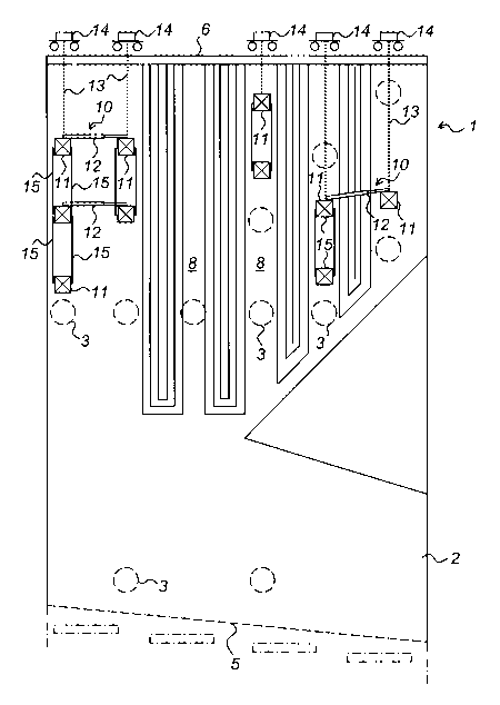
Fig. 1 is side view with partly broken-away compo-
nents and illustrates parts of a recovery boiler, in
which an apparatus according to the invention is used;
Fig. 2 is a side view and illustrates parts of the
long side of a lattice girder;
Fig. 3 is a top plan view and illustrates parts of
the upper side of the lattice girder;
Fig. 4 is an end view and illustrates three lattice
girders rranged one above the other, which are inter-
a
connected by means of steel bands arranged on the sides;
Fig. 5 is an end view and illustrates a first
enclosing holder with associated locking cotter pins;
Fig. 6 is an end view and illustrates a second
enclosing holder with an associated locking cotter pin;
Fig. 7 is a top plan view and illustrates parts of
the upper side of a telescopic plank;
Fig. 8 is a side view and illustrates parts of the
long side of the telescopic plank; and
Fig. 9 is a sectional view and illustrates.parts of
the upper side of the plank.
Description of a Preferred Embodiment
Fig. 1 illustrates parts of a pressure vessel 1 for
a recovery boiler, in which an apparatus according to
the invention is used for inspection and repair purposes.
However, it would be possible to use the apparatus for
the same purpose also in other types of pressure vessels,
such as a bark-fired boiler, or inside a vessel, such as
an oil tank. Moreover, it can be used in new construction
of such vessels.
The pressure vessel 1 in Fig. 1 has, among other
things, walls 2 with manholes 3 formed therein, a
so-called nose 4 mentioned by way of introduction, a
protective roof 5 and a roof 6, from which a number of
superheaters 7 are suspended.
CA 02541062 2006-03-31
WO 2005/033441 PCT/SE2004/001420
8
The superheater 7 constitutes one of the parts that
are of special interest to be examined in connection with
an inspection. However, they make such inspection diffi-
cult by forming, between them, narrow vertical passages,
which may have a height of several meters and are partly
positioned above the nose 4. Some of the passages extend
parallel to the plane of the drawing in Fig. T, and some
8 extend vertically to this plane. The manholes 3 are
preferably arranged at least at one end of the passages
8.
The apparatus according to the invention is shown
in Fig. 1 to the right and to the left in the form of two
platforms 10 with slightly different configurations. A
common feature of the two platforms 10 is that the compo-
nents included therein are identical since they consti-
tute parts of a construction kit which can be extended
as desired to be adjusted to the prevailing situation.
Each platform 10 includes lattice girders 11 and
telescopic planks 12 as the main components.
Of the girders 11, the uppermost are horizontally
suspended parallel to each other both in the passages 8
and outside the same by chains 13 hanging down from elec-
tric telphers 14 mounted on the roof 6 of the vessel 1.
The telphers are remote controlled and can advantageously
be used, for instance, in order to initially pull in a
girder into the vessel 1 through a suitable manhole 3.
The lower girders 11 are suspended from the superposed
girders 11 by means of steel bands 15 which are arranged
on both sides of the girders 11. The suspension of both
the upper and the lower girders 11 will be described in
more detail below with reference to Figs 4-6, and the
construction of the girders 11 will be discussed below
with reference to Figs 2-4.
The telescopic planks 12 shown in Fig. 1 rest on
girders 11 hanging at essentially the same level, and
extend, seen from above, perpendicular to these girders
11. They are thus arranged perpendicular also to the
CA 02541062 2006-03-31
WO 2005/033441 PCT/SE2004/001420
9
passages 8 and can therefore be used to reach the pas-
sages (those parallel to the plane of the drawing) which
are perpendicular to these passages 8. The construction
of the planks 12 will be described in detail below with
reference to Figs 7-9.
Fig. 2 is a side view of a part of a lattice girder
11, Fig. 3 is a top plan view of a corresponding part,
and Fig. 4 is an end view of a plurality of such girders
11. The girder 1l, which is rectangular in cross-section,
is made of aluminium and comprises four longitudinal main
pipes 16 arranged in the cross-sectional corners. A grid
structure of thinner pipes or rods 17, which stabilises
the main pipes 16, extends between these main pipes 16 in
a zigzag. On top of the two upper main pipes 16, a foot-
board plate 18 is attached, which has a grooved anti-skid
upper side 19. At the ends of the girder 11, coupling
means (not shown) of prior-art type can be arranged for
a possible extension of the girder 11 or for connection
of a ladder for instance.
For suspension of the girders 11, use is made, as
stated above, of chains 13 for the upper girders 11 and
steel bands 15 for the lower girders 11. The chains 13
as well as the steel bands 15 are attached, as is evident
from Fig. 4, to the girders 11 by enclosing holders 20,
21, of which the holder 20 is intended especially for the
upper girders 11 and is shown in more detail in Fig. 5,
and the holder 21 is intended for the lower girders 11
and is shown in more detail in Fig. 6.
The holder 20 comprises two essentially C-shaped
halves 22, 23 shaped according to the cross-sectional
contour of the lattice girder 11, with the openings fac-
ing one another, said halves being made of a bent band
material of steel. Said halves 22, 23 have lugs 24, 25
at their upper ends and lugs 26, 27 at their lower ends,
which at the upper ends consist of vertically upwardly
bent portions of the band material and which at the lower
ends consist of tubular sleeves which are welded to the
CA 02541062 2006-03-31
WO 2005/033441 PCT/SE2004/001420
band material. A cotter pin 28 is moved through the lugs
24, 25 for attaching the above-mentioned chains 13, said
cotter pin suitably belonging to a shackle 29, into which
a hook 30 at the lower end of a chain 14 can be hooked.
5 At the lower ends, the lugs 26, 27 are preferably con-
nected to each other by means of a locking cotter pin
31, which is moved through the tubular sleeves and then
locked.
The holder 21 also comprises two essentially
10 C-shaped halves 32, 33 shaped according to the cross-
sectional contour of the lattice girder 11, with the
openings facing one another, said halves being made of
a bent band material of steel. Said halves 32, 33 have
lugs 34, 35 at their upper ends and lugs 36, 37 at their
lower ends, which at both the upper and the lower ends
consist of tubular sleeves which are welded to the band
material. The lugs 34-37 are preferably connected to each
other by means of locking cotter pins 38 which are moved
through the tubular sleeves and then locked.
To attach the above-mentioned steel bands 15 to the
sides of the girders 11, the steel bands 15 have holes
39 formed at their ends, and both the holder 20 and the
holder 21 have holes 40 formed in their sides, through
which locking cotter pins 41 can be moved and then be
locked.
Fig. 7 is a top plan view of a part of a telescopic
plank 12, Fig. 8 is a side view of a corresponding part,
and Fig. 9 is a sectional view of a part of the plank 12
corresponding to the situation in Fig. 7. The plank 12
consists of an outer and an inner mutually telescoping
U section 42, 43, which have downwardly directed U open-
ings with ends 44, 45 curved inwards, which give the
telescopic plank 12 a good load-bearing capacity. For
reasons of safety, the sections 42, 43 have a grooved
anti-skid surface 46, 47 and a pullout-limiting means
48 for limiting the possible projection.
CA 02541062 2006-03-31
WO 2005/033441 PCT/SE2004/001420
11
The pullout-limiting means 48 comprises two pins 50
which are biased by means of a leaf spring 49 and which
for locking are arranged to be automatically moved from
the inner U section 43 through lock openings 51, 52 in
the legs of the U-shaped sections 42, 43. To allow simple
release, the pins 50 are fixedly connected to a cable 53
which is connected to both pins 50 and thus allows simul-
taneous release of the two pins 50.
The sections 42, 43, preferably the outer section
42, can also, for reasons of safety, at one end which is
adapted to rest on a girder 11 have at least one vertical
hole for insertion of a locking cotter pin, which is
arranged to engage in a corresponding hole in the upper
side of the girder 11.
A person skilled in the art will realise that the
above-described embodiment of the invention may be varied
in many ways within the scope of the claims, and that the
above-described platforms 10, depending on the number of
planks 12 that are arranged and the number of girders 11
arranged under and next to each other are usable for most
operations which are to be performed in the vessels at
issue and in which a scaffold is required.