Note : Les descriptions sont présentées dans la langue officielle dans laquelle elles ont été soumises.
CA 02541340 2011-01-31
1
BLASTING
Field of the Invention
This invention relates to blasting. it relates more specifically to blasting
of rock or other material by
means of a blasting substance charged into a drill hole extending into the
rock or other material to
be blasted.
Summary of the Invention
For purposes of this invention, the term "blasting" is to be interpreted
widely to cover, generally,
destruction of rock or other material by means of pressure generating or shock
wave generating
substances such as explosives, propellants, or the like. Likewise, the term
"blasting substance" is to
be interpreted to cover explosives, propellants and other pressure or shock
wave generating
substances.
In.accordance with a first aspect of this invention, there is provided a
method of charging a drill hole
extending between a mouth thereof at a surface, and a blind end or bottom
thereof remote from
the mouth, the method including
providing in the drill hole at a relatively low level toward said bottom a
lower layer of a
blasting substance, and a lower layer of a plunger material proximately above
the lower layer of
blasting substance;
providing in the drill hole at a relatively high level remote from said bottom
a higher layer of
a plunger material, spaced a predetermined distance above said lower layer of
plunger material, and
proximately above said higher layer of plunger material, a higher layer of a
blasting substance;
placing initiators in association with the respective layers of blasting
substances and
connecting the initiators to a controller for actuating the initiators at
predetermined time intervals.
The spacing between opposing surfaces of respectively said lower layer and
said higher layer of
plunger material may be of the same order of magnitude, i.e. between about 0,5
m and about 3 m.
The respective layers of plunger material may be flowable material allowing
placement in the drill
hole at the respective desired positions. Drill cuttings are a preferred
plunger material.
Said relatively low level may be spatially adjacent a bottom of the drill hole
and spaced above the
bottom by a predetermined distance. The spacing may be between about 0,5 m and
about 3 m,
CA 02541340 2011-01-31
2
advantageously between about 1 m and about 2 m, preferably about 1.5 m, but
depending on
several factors, such as the depth of the drill hole, the nature of the rock
or other material to be
blasted, the nature of the plunger material, the nature of the blasting
substance, and the like.
The method may include supporting in each respective case the layer of plunger
material and the
layer of blasting substance on a plug capable of being positioned in the drill
hole at a predetermined
level.
By way of development, preferably, the method may include providing plunger
material below the
lower layer of blasting substance to provide a lower composite layer,
providing plunger material
above the higher layer of blasting substance to provide a higher composite
layer, and providing one
or more further composite layers of blasting substance and plunger material in
the drill hole, with
spacings in-between, in series along the drill hole. Further, preferably, the
method may include
tamping the drill hole proximate its mouth.
In a variant method, the lower layer of blasting substance may be positioned
proximate and may be
supported on the bottom of the drill hole.
In accordance with a second aspect of this invention, there is provided a
method of blasting a drill
hole charged in accordance with the first aspect of this invention, the method
including actuating
the initiators by means of the controller. The initiators may be actuated
simultaneously. They may
be actuated electrically or electronically. Instead, they may be actuated
pyrotechnically.
The invention extends in accordance with a third aspect to a method of mining
including blasting an
array of drill holes, each in accordance with the second aspect of this
invention.
The invention extends in accordance with a fourth aspect to a charged drill
hole extending between
a mouth thereof at a surface, and a blind end or bottom thereof remote from
the mouth, including
a lower layer of a blasting substance at a relatively high level toward said
bottom, and a
lower layer of a plunger material proximately above the lower layer of
blasting substance;
a higher layer of a plunger material at a relatively high level remote from
said bottom, and
spaced a predetermined distance above said lower layer of plunger material,
and proximately above
said higher layer of plunger material, a higher layer of a blasting substance;
CA 02541340 2011-01-31
3
initiators placed in association with the respective layers of blasting
substances and having
connectors for connection to a controller for actuating the initiators at
predetermined time
intervals.
Thus, generally, the drill hole is charged in accordance with the first aspect
of this invention.
The spacing between opposing surfaces of respectively said lower layer and
said higher layer of
plunger material may be between about 0,5 m and about 3 m.
The respective layers of plunger material may be flowable material allowing
placement in the drill
hole at the respective desired positions. The plunger material may be drill
cuttings.
Said relatively low level may be spatially adjacent a bottom of the drill hole
and spaced above the
bottom by a predetermined distance. The spacing may be between about 0,5 m and
about 3 m, with
the preferred range and value, and provisos mentioned above.
In a preferred embodiment, in each respective case or in each respective
series, the layer of plunger
material and the layer of blasting substance may be supported on a plug
positioned in the drill hole
at a predetermined level.
By way of preferred development, the charged drill hole may include plunger
material provided
below the lower layer of blasting substance to form a lower composite layer,
plunger material
provided above the higher layer of blasting substance to form a higher
composite layer, and one or
more further composite layers of blasting substance and plunger material, with
spacings in-
between, in series along the drill hole.
The charged drill hole may include tamping material closing the drill hole
proximate its mouth.
In accordance with a fifth aspect of the invention, there is provided a
blasting operation including an
array of blast holes each in accordance with the fourth aspect.
The initiators may be connected to a common control.
CA 02541340 2011-01-31
4
In accordance with another aspect of the present invention, there is provided
a method of charging
and blasting a drill hole extending between a mouth thereof at a surface, and
a blind end or bottom
thereof remote from the mouth, the method steps of charging the drill hole
including
providing in the drill hole a lower layer of a blasting substance, and a lower
layer of a
plunger material proximately above the lower layer of blasting substance;
providing in the drill hole a higher layer of a plunger material, supported by
means of a plug
and spaced a predetermined distance above said lower layer of plunger material
to form a spacing,
and proximately above said higher layer of plunger material, a higher layer of
a blasting substance;
placing initiators in association with the respective layers of blasting
substances and
connecting the initiators to a controller for actuating the initiators at
predetermined time interval,
the method steps of blasting the charged drill hole including
actuating the initiators by means of the controller, thereby propelling the
lower layer of
plunger material by means of the lower layer of blasting substance into said
spacing, and propelling
the higher layer of plunger material by means of the higher layer of blasting
substance into said
spacing, thereby causing the lower layer of plunger material and the higher
layer of plunger material
to impinge upon each other, and causing conversion of kinetic energy
associated with the propelled
layers of plunger material into pressure or shock waves to effect destruction
of rock in the
surrounding material.
In accordance with another aspect of the present invention, there is provided
a charged drill hole
extending between a mouth thereof at a surface, and a blind end or bottom
thereof remote from
the mouth, including within the drill hole,
a lower layer of a blasting substance, and a lower layer of a plunger material
proximately
above the lower layer of blasting substance;
a higher layer of a plunger material, supported by means of a plug and spaced
a
predetermined distance above said lower layer of plunger material such as to
form a spacing
therebetween, and proximately above said higher layer of plunger material, a
higher layer of a
blasting substance;
initiators placed in association with the respective layers of blasting
substances and having
connectors for connection to a controller for actuating the initiators at
predetermined time
intervals,
an arrangement being provided wherein the lower and higher layers of plunger
material
oppose each other spatially, each layer of plunger material being backed by a
layer of blasting
substance, such that, in use, on actuation of the layers of blasting substance
the layers of plunger
CA 02541340 2011-01-31
material are propelled toward each other, to impinge upon each other and to
convert kinetic energy
associated with the propelled layers of plunger material into pressure or
shock waves to destruct
surrounding material.
5 Brief Description of the Drawings
The invention is now described by way of example with reference to the
accompanying
diagrammatic drawings, in which
Figure 1 is a sectional view of a charged drill hole in accordance with the
invention; and
Figure 2 is a truncated sectional view of a variant embodiment of a charged
drill hole in accordance
with the invention.
Detailed Description of the Invention
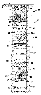
With reference to Figure 1 of the drawings, a charged drill hole in accordance
with the invention is
generally indicated by reference numeral 10.
A drill hole, indicated by reference numeral 12, extends along material, such
as rock, to be blasted.
The drill hole 12 has an open mouth 14 at a surface of the material to be
blasted, and a blind end or
blind bottom remote from the mouth and indicated by reference numeral 16. For
convenience of
terminology (e. g. higher/lower, above/below, and the like), it is assumed
that the drill hole is a
vertical drill hole extending from the mouth 14 downwardly to the bottom.
However other orientations, such as drill holes extending obliquely
downwardly, are also covered
mutatis mutandis as falling within the scope of this invention.
The charged drill hole 10 comprises a lower composite layer generally
indicated by reference
numeral 20. The position of the lower composite layer 20 is determined by
means of a plug 22 which
is lodged at a predetermined position in the drill hole 12. The plug 22 is a
sacrificial plug and may be
any plug suitable for this purpose.
In the embodiment illustrated in Figure 1, the lower composite layer 20, and
more specifically the
plug 22, is at a predetermined spacing, generally indicated by reference
numeral 23, above the
bottom 16. In this embodiment, the spacing 23 is about 1,5m.
CA 02541340 2011-01-31
6
The lower composite layer 20 extends from the position of the plug 22
upwardly. Immediately above
the plug 22, supported by, and partially contained within, the plug 22, is
provided a layer 24 of
plunger material in the form of drill cuttings. The layer 24, including a
portion of the layer 24
contained within the plug 22, is of the order of 150 mm length or thickness,
in this embodiment. The
reason for selecting the term "plunger material" for the layer 24 and its
mechanism of operation,
will be described herein below.
Immediately above the layer 24, there is provided a layer 26 of an explosive
which, in this
embodiment, is of the order of 9 m long.
Immediately above the layer 26 of explosive, there is provided a further layer
of plunger material
generally indicated by reference numeral 28.
The plunger material 28, in this embodiment, is of the order of about 0,6m
thick or long and it has an
upper, free surface 28.1.
At a relatively higher level remote from the bottom, there is provided a
higher composite layer
generally indicated by reference numeral 30.
The higher composite layer 30 is of generally similar construction and
composition to the lower
composite layer 20. It includes a plug 32, a layer 34 of plunger material, a
layer 36 of explosive, and a
layer 38 of plunger material having an upper, free surface 38.1. Furthermore,
the higher composite
layer 30 is spaced at a predetermined spacing 33 above the upper free surface
28.1 in a manner
similar to spacing of the lower composite layer 20 above the bottom 16. For
convenience, similar
reference numerals have been used for the respective layers or components and
they are not again
described. The length of the layer 36 of explosive, for the higher composite
layer, is of the order of
about 6 m.
The general arrangement may be repeated as many times as required, depending
also on the depth
of the drill hole. Generally, all of the composite layers have a more or less
central charge of
explosives flanked above and below by a layer of plunger material and each
composite layer is based
or supported on a plug 22, 32, or the like.
CA 02541340 2011-01-31
7
Toward the top of the drill hole 12, there is provided a plug 42 supporting a
layer of plunger material
in the form of drill cuttings indicated by reference numeral 44 and having
thereabove a charge of
explosives 46. Above the charge of explosives 46, tamping material, for
example in the form of hard
rock, drill cuttings, or the like is provided indicated by reference numeral
48, and which extends
generally to the mouth 14. The plug 42, the layer 44 of plunger material, the
charge of explosives
46m, and the tamping material 44 define a composite layer 40.
In each of the layers of explosives, there is provided one or more initiators
27, 37, 47 for actuating
the explosives. In this embodiment, the initiators are electric or electronic
and are controlled by
means of a controller 57. In another embodiment or application, the initiators
may be pyrotechnic.
The Applicant does not wish to be bound by theory, but an explanation of the
Applicant's hypothesis
of the mechanism of operation when the explosives are actuated, is expected to
assist a reader's
understanding of the invention.
Generally, the Applicant expects that it would wish the explosives to be
actuated generally
simultaneously, but this is not at this stage regarded as of particular
importance, and further tests,
also depending on various factors, may indicate that time lags may be
advantageous.
The general hypothesis is based on two aspects. First, it is believed that
actuation of an explosive
would propel the adjacent material, i.e. the plunger material, in the nature
of a plunger away from
the centre of actuation i.e. along a respective spacing, 23, 33, 43, or the
like, bearing in mind that
such spacing would generally offer the route of least resistance. It is
expected that at least the
spacings remote from the bottom 16 would consist of air, whereas the spacing
23 adjacent the
bottom may consist of air, or water in the case of wet holes, or partially
water and partially air.
The second aspect is that the plunger propelled by actuation of the explosive
will necessarily
impinge on an obstacle and will come to a sudden halt. For example, the layer
of plunger material 24
will impinge and come to a halt when it hits the bottom 16, and in the case of
the plunger material
28 propelled upwardly when the layer of explosive 26 is actuated, and the
plunger material 34 which
will be propelled downwardly when the explosive 36 is actuated, they will
impinge upon each other
to cause the sudden halt.
CA 02541340 2011-01-31
8
It is to be appreciated that propelling of the plunger material converts the
chemical or potential
energy, associated with actuation of the explosive, into or partially into
kinetic energy in that the
respective layers or masses of plunger material are propelled at high speed.
Initial calculations
indicate that very high amounts of kinetic energy are involved.
Thus, when the carrier of the kinetic energy (i.e. the mass proceeding at high
speed) is forced to a
sudden halt, the kinetic energy is again converted into energy associated with
pressure or shock
wave which causes very effective destruction of rock or other surrounding
material, in accordance
with preliminary tests conducted by the Applicant.
The Applicant believes that this invention has the possibility of greatly
reducing the amount of
explosives required to conduct blasting operations. This will have the direct
effect of a
commensurate cost saving in respect of explosives, which makes out a high
percentage of the total
cost of blasting. It is further expected to have the subsidiary advantages,
which may be very
important in some applications, of focussing or concentrating the destructive
effort intermediate the
bottom 16 of the drill hole and the mouth 14 of the drill hole thus limiting
or virtually totally
obviating unrequired and sometimes undesired destruction of rock below the
bottom 16.
Furthermore, it limits and possibly virtually obviates transfer of energy
above the level of the mouth,
for example limiting or obviating fly rock, and other undesirable side effects
of blasting.
With reference to Figure 2, in a variation of the embodiment of Figure 1, an
explosive substance 126
is positioned proximate the bottom 16 to be supported on the bottom 16.
Immediately above the
layer 126 of explosive substance, there is provided a layer 128 of a plunger
material, conveniently in
the form of drill cuttings, and forming a free upper surface 128.1. An
initiator 127 is provided with
the explosive substance 126 and is connected to a controller such as the
controller 57. Spaced above
the free upper surface 128.1 (i.e. with an air space in between) there is
provided one or more
composite layers 20, 30 and the like as described with reference to Figure 1.