Note : Les descriptions sont présentées dans la langue officielle dans laquelle elles ont été soumises.
CA 02541610 2006-04-03
PATENT
Attorney Docket No.: 22.1596 (SLB.0004)
DOWNHOLE ACTUATION TOOLS
BACKGROUND
Field of the Invention
[0001] Implementations of various technologies described herein generally
relate
to downhole actuation tools.
Description of the Related Art
10002] The following descriptions and examples are not admitted to be prior
art
by virtue of their inclusion within this section.
[0003] Mechanical rupture discs and shear-pins have been widely used as a
method for controlling the actuation of downhole tools, such as packers,
valves and
the like. However, for some applications where maximum pressures may be
limited,
downhole assemblies may be complex and multiple tools may need to be
controlled
serially, mechanical rupture discs and shear-pins may not provide sufficient
control.
[0004] Therefore, a need may exist in the art for improved methods and
apparatuses for actuating downhole tools.
SUMMARY
10005] Described herein are implementations of various technologies for an
apparatus for actuating a downhole tool. In one implementation, the apparatus
may
include a pressure sensor for receiving one or more pressure pulses and an
electronics module in communication with the pressure sensor. The electronics
module may be configured to determine whether the pressure pulses are
indicative
of a command to actuate the downhole tool. The apparatus may further include a
motor in communication with the electronics module. The motor may be
configured
to provide a rotational motion. The apparatus may further include a coupling
mechanism coupled to the motor. The coupling mechanism may be configured to
translate the rotational motion to a linear motion. The apparatus may further
include
2
CA 02541610 2008-07-21
78543-225
a valve system coupled to the coupling mechanism. The valve system may be
configured to actuate the downhole tool when the valve system is in an open
phase.
(0006] In another implementation, the valve system may include a lead screw
coupled to the coupling mechanism, a sealing plug disposed inside a plug port,
and
a pin coupled to the lead screw. The pin may be configured to confine the
sealing
plug inside the plug port when the valve system is in a closed phase. The
valve
system may further include a valve channel in communication with the plug port
and
a compression spring disposed inside the valve channel.
(00071 In yet another implementation, -the valve system may include an
atmospheric chamber and a vent port in communication with the atmospheric
chamber. The valve system may further include a lead screw coupled to the
coupling mechanism, an o-ring disposed inside the atmospheric chamber and a
sealing pin disposed between the lead screw and the vent port through the o-
ring
such that the sealing pin and the o-ring form a seal with the vent port, when
the
valve system is in a closed phase.
3
CA 02541610 2008-07-21
78543-225
In still another implementation, there is provided
an apparatus for actuating a downhole tool, comprising: an
inlet port in communication with well fluid; a pressure
sensor for receiving one or more pressure pulses; an
electronics module in communication with the pressure
sensor, wherein the electronics module is configured to
determine whether the pressure pulses are indicative of a
command to actuate the downhole tool; a motor in
communication with the electronics module, wherein the motor
is configured to provide a rotational motion; a coupling
mechanism coupled to the motor, wherein the coupling
mechanism is configured to translate the rotational motion
to a linear motion; and a valve system coupled to the
coupling mechanism to control communication between the
inlet port and a control line extending to the downhole tool
to selectively isolate the downhole tool from pressure
exerted by the well fluid, wherein the valve system is
configured to actuate the downhole tool when the valve
system is in an open phase.
In yet another implementation, there is provided
an apparatus for actuating a downhole tool, comprising: a
pressure sensor for receiving one or more pressure pulses;
an electronics module in communication with the pressure
sensor, wherein the electronics module is configured to
determine whether the pressure pulses are indicative of a
command to actuate the downhole tool; a motor in
communication with the electronics module, wherein the motor
is configured to provide a rotational motion; a coupling
mechanism coupled to the motor, wherein the coupling
mechanism is configured to translate the rotational motion
to a linear motion; and a valve system configured to actuate
the downhole tool when the valve system is in an open phase,
wherein the valve system comprises: a lead screw coupled to
3a
CA 02541610 2008-07-21
78543-225
the coupling mechanism; a sealing plug disposed inside a
plug port; a pin coupled to the lead screw, wherein the pin
is configured to confine the sealing plug inside the plug
port when the valve system is in a closed phase; a valve
channel in communication with the plug port; and a
compression spring disposed inside the valve channel.
In a further implementation, there is provided an
apparatus for actuating a downhole tool, comprising: a
pressure sensor for receiving one or more pressure pulses;
an electronics module in communication with the pressure
sensor, wherein the electronics module is configured to
determine whether the pressure pulses are indicative of a
command to actuate the downhole tool; a motor in
communication with the electronics module, wherein the motor
is configured to provide a rotational motion; a coupling
mechanism coupled to the motor, wherein the coupling
mechanism is configured to translate the rotational motion
to a linear motion; and a valve system configured to actuate
the downhole tool when the valve system is in an open phase,
wherein the valve system comprises: an atmospheric chamber;
a vent port in communication with the atmospheric chamber; a
lead screw coupled to the coupling mechanism; an o-ring
disposed inside the atmospheric chamber; and a sealing pin
disposed between the lead screw and the vent port through
the o-ring such that the sealing pin and the o-ring form a
seal with the vent port, when the valve system is in a
closed phase.
[0008] The claimed subject matter is not limited to
implementations that solve any or all of the noted
disadvantages. Further, the summary section is provided to
introduce a selection of concepts in a simplified form that
are further described below in the detailed description
section. The summary section is not intended to identify
3b
CA 02541610 2008-07-21
78543-225
key features or essential features of the claimed subject
matter, nor is it intended to be used to limit the scope of
the claimed subject matter.
BRIEF DESCRIPTION OF THE DRAWINGS
[0009] Implementations of various technologies will
hereafter be described with reference to the accompanying
drawings. It should be understood, however, that the
accompanying drawings illustrate only the various
implementations described herein and are not meant to limit
the scope of various technologies described herein.
3c
CA 02541610 2006-04-03
PATENT
Attorney Docket No.: 22.1596 (SLB.0004)
[0010] Figure 1 illustrates a schematic diagram of a tubing string that may
include
a downhole actuation tool in accordance with implementations of various
technologies described herein.
[0011] Figure 2 illustrates a block diagram of a downhole actuation tool in
accordance with implementations of various technologies described herein.
[0012] Figure 3 illustrates a series of pressure pulses that may be used to
trigger
the downhole actuation tool in accordance with various implementations
described
herein.
[0013] Figure 4 illustrates a schematic diagram of an electronics module that
may
be used to interpret the pressure pulses in accordance with various
implementations
described herein.
[0014] Figure 5A illustrates a schematic diagram of a valve system in a closed
phase in accordance with one implementation of various technologies described
herein.
[0015] Figure 5B illustrates a schematic diagram of a valve system in an open
phase in accordance with one implementation of various technologies described
herein.
[0016] Figure 6A illustrates a schematic diagram of a valve system in a closed
phase in accordance with another implementation of various technologies
described
herein.
[0017] Figure 6B illustrates a schematic diagram of a valve system in an open
phase in accordance with another implementation of various technologies
described
herein.
[0018] Figure 7A illustrates a schematic diagram of a valve system in a closed
phase in accordance with yet another implementation of various technologies
described herein.
4
CA 02541610 2006-04-03
PATENT
Attorney Docket No.: 22.1596 (SLB.0004)
[0019] Figure 7B illustrates a schematic diagram of a valve system in an open
phase in accordance with yet another implementation of various technologies
described herein.
DETAILED DESCRIPTION
[0020] As used here, the terms "up" and "down"; "upper" and "lower";
"upwardly"
and downwardly"; "below" and "above"; and other similar terms indicating
relative
positions above or below a given point or element may be used in connection
with
some implementations of various technologies described herein. However, when
applied to equipment and methods for use in wells that are deviated or
horizontal, or
when applied to equipment and methods that when arranged in a well are in a
deviated or horizontal orientation, such terms may refer to a left to right,
right to left,
or other relationships as appropriate.
[0021] Figure 1 illustrates a schematic diagram of a tubing string 100 that
may
include a downhole actuation tool 10 in accordance with implementations of
various
technologies described herein. The tubing string 100 may be disposed inside a
wellbore 110, which may be lined with a casing or liner 120. In one
implementation,
the downhole actuation tool 10 may be disposed on an outside surface of the
tubing
string 100. It should be understood, however, that in some implementations the
downhole actuation tool 10 may be disposed anywhere on the tubing string 100,
including inside the tubing string 100. The downhole actuation tool 10 may be
configured to actuate a downhole tool 20, such as a ball valve, a sliding
sleeve, a
packer, a cutting tool or any other downhole tool commonly known by persons
having ordinary skill in the art. Illustratively, the downhole actuation tool
10 may be
disposed above the downhole tool 20. It is to be understood that in some
implementations the downhole actuation tool 10 may be disposed below the
downhole tool 20 or at the substantially the same level as the downhole tool
20.
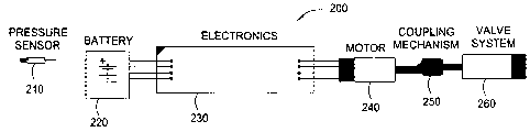
[0022] Figure 2 illustrates a block diagram of a downhole actuation tool 200
in
accordance with implementations of various technologies described herein. In
one
implementation, the downhole actuation tool 200 may include a pressure sensor
CA 02541610 2006-04-03
PATENT
Attorney Docket No.: 22.1596 (SLB.0004)
210, a battery 220, an electronics module 230, a motor 240, a coupling
mechanism
250 and a valve system 260.
[0023] The pressure sensor 210 may be configured to receive pressure pulses.
Figure 3 illustrates a series of pressure pulses that may be used in
accordance with
various implementations described herein. The vertical axis in Figure 3
represents
pressure in kpsi, while the horizontal axis represents time in minutes. In one
implementation, the pressure sensor 210 may be a pressure transducer. Although
implementations of various technologies described herein are described with
reference to a pressure sensor, it should be understood that other
implementations
may use other types of sensing devices, such as light transducers, acoustic
transducers, electromagnetic wave transducers and the like.
[00241 The battery 220 may be configured to supply electrical energy to the
electronics module 230 and the motor 240. Although implementations of various
technologies are described herein with reference to a battery as the power
source, it
should be understood that in some implementations other types of power source,
such as, fuel cell, turbine generators and the iike, may be used to supply
energy to
the electronics module 230 and the motor 240.
[0025] Figure 4 illustrates an electronics module 400 that may be used in
various
implementations described herein. In one implementation, the electronics
module
400 may include a microprocessor 410 coupled via a bus 408 to a non-volatile
memory 402 (e.g., a read only memory (ROM)) and a random access memory
(RAM) 430. An analog-to-digital (A/D) converter 422 and a motor interface 424
may
also be coupled to the bus 408. The non-volatile memory 402 may be configured
to
store instructions that form a computer program 404 that, when executed by the
microprocessor 410, causes the microprocessor 410 to detect the pressure
pulses
and recognize sequences of pressure pulses as commands to activate the motor
240. The non-volatile memory 402 may also be configured to store signature
data
406 that correspond to various sequences of pressure pulses. Such signature
data
may be used by the microprocessor 410 to interpret sequences of pressure
pulses.
6
CA 02541610 2008-07-21
78543-225
[0026] The A/D converter 422 may be coupled to a sample and hold (S/H) circuit
420 that may be configured to receive an analog signal from the pressure
sensor
210 indicative of the sensed pressure pulse. The S/H circuit 420 may be
configured
to sample the analog signal and provide the sampled signal to the A/D
converter
422, which in turn may convert the sampled signal into digital sampled data
412
stored in the RAM 430. The electronics module 400 along with the pressure
sensor
210 and the battery 220 may be described in more detail in commonly assigned
United States Patent Nos. 6,182,764; 6,550,538 and 6,536,529.
Although various implementations are described
herein with reference to the motor 400, it should be understood that some
implementations may use a microcontroller having all the functionality of the
motor
400. In addition, in some implementations, the S/H circuit 420 may be an
optional
component of the motor 400.
[00271 The motor 240 may be configured to apply torque or turning force to the
coupling mechanism 250. The motor 240 may be coupled to the coupling
mechanism 250 through an output shaft (not shown). In one implementation, the
motor 240 may include a transmission, such as a planetary gear configured
transmission with a ratio of approximately 600 to 1, for example. In another
implementation, the motor 240 may be a stepper motor.
[0028] The coupling mechanism 250 may be configured to receive the torque
from the motor 240 and use that torque to turn a lead screw 255 connected
thereto,
as shown in Figure 5A. In this manner, the coupling mechanism 250 may be
configured to translate a rotational motion, i.e., the torque received from
the motor
240, to a linear motion, i.e., by linearly moving the lead screw 255 in
response to the
torque. In one implementation, the coupling mechanism 250 may be connected to
the output shaft of the motor 240 with a set screw (not shown) to facilitate
easy
removal of the valve system 260 from the motor 240. It should be understood,
however, that in some implementations the coupling mechanism 250 may be
connected to the output shaft of the motor 240 by other means, such as a press-
fit
pin. In another implementation, the coupling mechanism 250 may be a shaft
coupling mechanism. In yet another implementation, the coupling mechanism 250
7
CA 02541610 2006-04-03
PATENT
Attorney Docket No.: 22.1596 (SLB.0004)
may be connected to the lead screw 255 with a press-fit pin 258. While the
lead
screw 255 is inserted into the coupling mechanism 250, the press-fit pin 258
may be
pressed into a transversely-drilled hole through the lead screw 255. The press-
fit
pin 258 is held captive but free to slide in a transverse machined slot
through the
coupling mechanism 250 that allows both rotational and linear motion of the
lead
screw 255 to occur when the coupling mechanism 250 is turned by the motor 240.
[0029] In one implementation, the lead screw 255 may be an ACME screw.
However, it should be understood that other types of lead screws may be used
in
other implementations. The lead screw 255 may be configured to linearly move
within a nut 265. That is, the lead screw 255 may move in and out of the nut
265
based on the direction of the torque. Accordingly, the nut 265 may be an ACME
nut,
thereby making the lead screw 255 and the nut 265 a matched set. In one
implementation, the lead screw 255 and the nut 265 may be a'/4 - 20 ACME screw
and nut. The pitch and starts of the lead screw 255 may be configured to
determine
the torque required to back out the lead screw 255 to open the valve system
260.
For instance, a single start lead screw and nut may have negative efficiency
for back
driving, and as such, the motor 240 may provide the torque to back out the
lead
screw. On the other hand, a more efficient lead screw and nut with multiple
starts
and higher lead angles may have positive efficiency for back driving, and as
such,
the motor 240 may provide the braking torque to prevent the lead screw 255
from
backing out when pressure is applied to the valve system 260. In this manner,
the
back driving characteristics of the multi-start lead screw and nut may be used
to
advantage of designing an essentially zero electrical power operated, high
pressure
valve system. In one implementation, on one end of the lead screw 255, the
threads
may be removed and a small diameter hole may be drilled cross ways to accept
the
press-fit pin 258 used to connect to the coupling mechanism 250.
[ooso] In another implementation, the other end of the lead screw 255 may
include a small diameter pin 510 machined for holding a sealing plug 501 in
place.
In one implementation, the pin 510 may be free floating, i.e., not coupled to
the lead
screw 255. The sealing plug 501 may be used to form a high pressure seal at a
plug port 520. The elastomeric function of the sealing plug 501 is similar to
an o-
8
CA 02541610 2006-04-03
PATENT
Attorney Docket No.: 22.1596 (SLB.0004)
ring. The sealing plug 501 may be configured to fill the void between the pin
510
and the cylinder wall of the plug port 520 when energized by either the
compression
of the pin 510 and/or hydraulic pressure, which will be described in more
detail in the
paragraphs below. Thus, the sealing plug 501, when placed inside the plug port
520
and held in place by the pin 510, may form a high pressure seal with the plug
port
520. The diameter of the pin 510, the diameter of the plug port 520 and the
dimensions of the sealing plug 501 may be designed to complement each other to
form an effective seal. In one implementation, the diameter of the plug port
520 and
the diameter of the sealing plug 501 may be configured to minimize the amount
of
power applied by the motor 240 to open the valve system 260.
[0031] The valve system 260 may further include an inlet port 540 and a
control
line 550. In an open phase, well fluid from outside the downhole actuation
tool 200
may flow from the inlet port 540 through the control line 550 to the downhole
tool 20,
as will be described in more detail later. The valve system 260 may further
include a
pilot (or floating) piston 530 to facilitate the open and closed phases of the
valve
system 260. The pilot piston 530 may include a large portion 531 disposed
inside a
valve chamber 560 and a small portion 532 disposed inside the control line
550.
The pilot piston 530 may be sealed to the valve chamber 560 with o-rings 535.
[0032] The valve system 260 may further include a valve channel 570 coupled to
the valve chamber 560. The valve channel 570 may be configured such that its
flow
area is significantly less than the flow area of the valve chamber 560. In one
implementation, the flow area of the valve chamber 560 is about 0.071 inches3
while
the flow area of the valve channel 570 is 0.001 inches3. As such, the flow
area of
the valve chamber 560 is about 74 times greater than the flow area of the
valve
channel 570. The valve system 260 may further include a restriction channel
580
connecting the plug port 520 with the valve channel 570. In one
implementation, the
diameter of the restriction channel 580 is smaller than the diameter of the
plug port
520.
[0033] In one implementation, the space between the sealing plug 501 and the
pilot piston 530 may be filled with hydraulic oil. That space may be defined
by a
9
CA 02541610 2006-04-03
PATENT
Attorney Docket No.: 22.1596 (SLB.0004)
portion of the plug port 520, the restriction channel 580, the valve channel
570 and a
portion of the valve chamber 560. Although the valve system 260 may be
described
herein with reference to hydraulic oil, it should be understood that in some
implementations the valve system 260 may use any non-compressible fluid that
may
be used downhole, such as DC200-1000CS silicone oil made by Dow Corning from
Midland, Michigan.
[0034] Figure 5A illustrates a schematic diagram of the valve system 500 in a
closed phase in accordance with implementations of various technologies
described
herein. In the closed phase, no electrical signal or power is applied to the
motor
240. The motor 240 functions as a brake to prevent back drive. The coupling
mechanism 250 transfers the braking action from the motor 240 to the lead
screw
255. The pin 510 confines the sealing plug 501 inside the plug port 520 to
seal off
the valve chamber 560. The hydraulic oil prevents the pilot piston 530 from
moving
when external pressure from well fluid is applied against the pilot piston
530.
Because the hydraulic oil expands with increase in temperature, the pilot
piston 530
may be positioned inside the valve chamber 560 in a way that would allow the
pilot
piston 530 to move in response to temperature changes.
[0035] Figure 5B illustrates a schematic diagram of the valve system 500 in an
open phase in accordance with implementations of various technologies
described
herein. During the opening phase, electrical signal or power may be applied to
the
motor 240 to cause the motor 240 to turn. In one implementation, less than one
watt
is applied to the motor 240 to open the valve system 500. In response, the
coupling
mechanism 250 may cause the lead screw 255 to retract from the nut 265, i.e.,
to
move toward the motor 240. As the lead screw 255 is turned, the pin 510 is
withdrawn from the plug port 520, allowing the sealing plug 501 to be pushed
out by
pressure from the hydraulic oil. Once the sealing plug 501 is removed from the
plug
port 520, the hydraulic oil begins to flow out of the plug port 520. As the
hydraulic oil
flows from the plug port 520 to an atmospheric chamber 590, the pilot piston
530
moves toward the direction of the sealing plug 501 until a stopping region 575
of the
valve chamber 560 is reached. The stopping region 575 may have a variety of
finish, including drill point, flat, radiused and the like. As the pilot
piston 530 moves
CA 02541610 2006-04-03
PATENT
Attorney Docket No.: 22.1596 (SLB.0004)
toward the sealing plug 501, communication between the inlet port 540 and the
control line 550 is opened, allowing well fluid to flow from the inlet port
540 through
the control line 550 to the downhole tool 20. In one implementation, the
volume of
the atmospheric chamber 590 is greater than the volume of the valve chamber
560.
In another implementation, once the downhole actuation tool 200 is opened, it
may
not be closed without redressing the downhole actuation tool 200.
[0036] Figure 6A illustrates a schematic diagram of a valve system 600 in a
closed phase in accordance with implementations of various technologies
described
herein. In one implementation, the valve system 600 includes the same
components as the valve system 500 described in the above paragraphs, with a
few
exceptions. For example, the valve system 600 may include a compression spring
610 disposed inside a valve channel 670. In one implementation, the
compression
spring 610 may be held inside the valve channel 670 by a hollow set screw 620.
[0037) The valve system 600 may further include a floating pin 630 disposed
between the compression spring 610 and a sealing plug 640. The floating pin
630
may have a piston portion 632 configured to press against the sealing plug 640
and
a cylindrical portion 635 configured to provide a shoulder for the compression
spring
610 to press against. The compression spring 610 may be configured to push the
floating pin 630 against the sealing plug 640, thereby squeezing the sealing
plug
640 between the floating pin 630 and a lead screw 655. When squeezed, the
sealing plug 640 may shorten axially and expand radially, thereby causing the
sealing plug 640 to fit tight against a plug port 650 and create a pressure
seal. In
one implementation, the diameter of the piston portion 635 is smaller than the
diameter of the plug port 650. In another implementation, the diameter of the
cylindrical portion 635 is substantially the same as the diameter of the
compression
spring 610. In this manner, the compression spring 610 against the sealing
plug 640
allows the sealing plug 640 to seal well at low pressure as well as at high
pressure.
[0038] In the closed phase, no electrical signal or power is applied to the
motor
240. As with the valve system 500, the motor 240 functions as a brake to
prevent
back drive. The coupling mechanism 250 transfers the braking action from the
11
CA 02541610 2008-07-21
78543-225
motor 240 to the lead screw 655, which confines the sealing plug 640 inside
the plug
port 650. The hydraulic oil between the sealing plug 640 and a pilot piston
660
prevents the pilot piston 660 from moving when external pressure from well
fluid is
applied against the pilot piston 660.
[0039] Figure 6B illustrates a schematic diagram of the valve system 600 in an
open phase in accordance with implementations of various technologies
described
herein. During the opening phase, electrical signal or power may be applied to
the
motor 240 to cause the motor 240 to turn. In response, the coupling mechanism
250 may cause the lead screw 655 to retract from the nut 665, i.e., to move
toward
the motor 240. As the lead screw 655 is withdrawn from the plug port 650, the
sealing plug 640 is set free to be pushed out by pressure from the hydraulic
oil and
the compression spring 610 pushing against the floating pin 630. As the
hydraulic
oil drains from the plug port 650 into an atmospheric chamber 690, the pilot
piston
660 moves toward the direction of the sealing plug 640 until a stopping region
675 of
the valve chamber 680 is reached. In one implementation, the volume of the
atmospheric chamber 690 is greater than the volume of the valve chamber 680.
As
the pilot piston 660 moves toward the sealing plug 640, communication between
an
inlet port 654 and a control line 656 is opened, allowing well fluid to flow
from the inlet
port 654 through the control line 656 to the downhole tool 20.
[0040] Figure 7A illustrates a schematic diagram of a valve system 700 in a
closed phase in accordance with implementations of various technologies
described
herein. In one implementation, the valve system 700 includes the same
components as the valve system 500 described in the above paragraphs, with a
few
exceptions. For instance, in lieu of the sealing plug 501, the valve system
700 may
include an o-ring 710 disposed inside an atmospheric chamber 790. The valve
system 700 may further include a sealing pin 720 disposed between a lead screw
755 and a vent port 725 through the o-ring 710. A portion of the sealing pin
720
may be disposed inside the o-ring 710 to form a seal with the o-ring 710. A
back up
disc 730 may be disposed adjacent the o-ring 710 to enhance the reliability of
the o-
ring 710. In one implementation, the sealing pin 720 may be held by a recess
portion 760 of a lead screw 755. As such, in the closed phase, the sealing pin
720
12
CA 02541610 2006-04-03
PATENT
Attorney Docket No.: 22.1596 (SLB.0004)
and the o-ring 710 may be configured to seal a vent port 725. In another
implementation, as opposed to free floating, the sealing pin 720 may be
coupled to
the lead screw 755. The diameter of the sealing pin 720, the diameter of the
vent
port 725 and the dimensions of the o-ring 710 may be designed to complement
each
other to form an effective seal. In one implementation, a 0.062 diameter
sealing pin
may be used to form a seal with the o-ring 710.
[0041] In the closed phase, the o-ring 710 fills the void between the sealing
pin
720 and the center hole of the back up disc 730 and the void between the wall
of the
atmospheric chamber 790 and the back up disc 730, when energized by either the
compression of the sealing pin 720 and/or hydraulic pressure. In one
implementation, the o-ring 710 may be a fluorocarbon Viton elastomer with a
durometer of 95, which may be made by DuPont Dow Elastomers from Wilmington,
Delaware. However, it should be understood that in some implementations the o-
ring 710 may be made from any elastomer material rated for downhole
environment.
[0042] In the closed phase, no electrical signal or power is applied to the
motor
240. The motor 240 functions as a brake to prevent any back drive. The
coupling
mechanism 250 transfers the braking action from the motor 240 to the lead
screw
755. The hydraulic oil prevents the pilot piston 770 from moving when external
pressure from well fluid is applied against the pilot piston 770.
[0043] Figure 7B illustrates a schematic diagram of the valve system 700 in an
open phase in accordance with implementations of various technologies
described
herein. During the opening phase, electrical signal or power may be applied to
the
motor 240 causing the motor 240 to turn. In response, the coupling mechanism
250
may cause the lead screw 755 to retract from the nut 765, i.e., to move toward
the
motor 240. As the lead screw 755 is turned, the sealing pin 720 is withdrawn
from
the o-ring 710. If the sealing pin 720 is coupled to the lead screw 755, the
lead
screw 755 will pull the sealing pin 720 from the o-ring 710 at the cost of
higher o-ring
friction and higher torque requirements from the motor 240. On the other hand,
if
the sealing pin 720 is loose or free to turn with respect to the lead screw
755, the o-
ring friction is not transferred to the lead screw 755 and the motor torque
13
CA 02541610 2008-07-21
78543-225
requirements are reduced; however, hydraulic pressure may be required to
withdraw
the sealing pin 720 from the o-ring 710. As the hydraulic oil that was trapped
between the sealing pin 720 and the pilot piston 770 drains from the vent port
725
into the atmospheric chamber 790, the pilot piston 770 moves toward the
direction of
the o-ring 710 until the stopping region 775 of the valve chamber 780 is
reached. As
the pilot piston 770 moves toward the direction of the o-ring 710,
communication
between an inlet port 754 and a control line 756 is opened, allowing well
fluid to flow
from the inlet port 754 through the control line 756 to the downhole too120.
In one
implementation, the volume of the atmospheric chamber 790 is greater than the
volume of the valve chamber 780. Although implementations of various
technologies have described the flow of well fluid from the inlet port to the
control
line, it should be understood that in other implementations the well fluid may
flow
from the control line to the inlet port.
[0044] In this manner, various implementations of the downhole actuation tool
may be used as a rupture disc. One advantage various downhole actuation tool
implementations have over conventional rupture discs is that various downhole
actuation tool implementations are not limited by depth or pressure, since
they may
be actuated by a sequence of pressure pulses. Furthermore, various downhole
actuation tool implementations may also provide more precision in controlling
downhole tool actuation. Various downhole actuation tool implementations may
be
operated using less than one watt of power applied to the motor 240 and a
differential pressure ranging from less than lkpsi to greater than 20kpsi.
Such
differential pressure may be caused by the trapped low pressure in the
atmospheric
chamber and the high pressure from well fluid.
(0045] Although the subject matter has been described in language specific to
structural features and/or methodological acts, it is to be understood that
the subject
matter defined in the appended claims is not necessarily limited to the
specific
features or acts described above. Rather, the specific features and acts
described
above are disclosed as example forms of implementing the claims.
14