Sélection de la langue

Search

Sommaire du brevet 2541673 

Énoncé de désistement de responsabilité concernant l'information provenant de tiers

Une partie des informations de ce site Web a été fournie par des sources externes. Le gouvernement du Canada n'assume aucune responsabilité concernant la précision, l'actualité ou la fiabilité des informations fournies par les sources externes. Les utilisateurs qui désirent employer cette information devraient consulter directement la source des informations. Le contenu fourni par les sources externes n'est pas assujetti aux exigences sur les langues officielles, la protection des renseignements personnels et l'accessibilité.

Disponibilité de l'Abrégé et des Revendications

L'apparition de différences dans le texte et l'image des Revendications et de l'Abrégé dépend du moment auquel le document est publié. Les textes des Revendications et de l'Abrégé sont affichés :

  • lorsque la demande peut être examinée par le public;
  • lorsque le brevet est émis (délivrance).
(12) Demande de brevet: (11) CA 2541673
(54) Titre français: SYSTEME D'OSSATURE POUR BATIMENTS
(54) Titre anglais: FRAMING SYSTEM FOR BUILDINGS
Statut: Réputée abandonnée et au-delà du délai pour le rétablissement - en attente de la réponse à l’avis de communication rejetée
Données bibliographiques
(51) Classification internationale des brevets (CIB):
  • E04C 2/38 (2006.01)
(72) Inventeurs :
  • MEEK, MICHAEL A. (Etats-Unis d'Amérique)
  • PLUEARD, DAVID D. (Etats-Unis d'Amérique)
(73) Titulaires :
  • ALLIED TUBE & CONDUIT CORPORATION
(71) Demandeurs :
  • ALLIED TUBE & CONDUIT CORPORATION (Etats-Unis d'Amérique)
(74) Agent: SMART & BIGGAR LP
(74) Co-agent:
(45) Délivré:
(86) Date de dépôt PCT: 2004-10-06
(87) Mise à la disponibilité du public: 2005-04-21
Licence disponible: S.O.
Cédé au domaine public: S.O.
(25) Langue des documents déposés: Anglais

Traité de coopération en matière de brevets (PCT): Oui
(86) Numéro de la demande PCT: PCT/US2004/034162
(87) Numéro de publication internationale PCT: WO 2005035891
(85) Entrée nationale: 2006-04-05

(30) Données de priorité de la demande:
Numéro de la demande Pays / territoire Date
10/683,947 (Etats-Unis d'Amérique) 2003-10-10

Abrégés

Abrégé français

Système d'ossature pour bâtiments, qui comporte une pluralité d'entretoises et de rails montés ensemble pour former un système d'ossature unique en son genre. Chaque entretoise présente un corps à extension longitudinale, des pans terminaux opposés pliables et des brides opposées qui s'étendent vers l'extérieur à partir du corps. Chacune des brides opposées comporte également une seconde bride qui s'étend vers l'extérieur par rapport aux brides opposées, à un angle d'environ quatre-vingt-dix degrés. Une pluralité de rails est montée sur la pluralité d'entretoises. Chaque rail possède un corps à extension longitudinale et des brides de rail opposées qui s'étendent vers l'extérieur à partir dudit corps de rail.


Abrégé anglais


A framing system for buildings that includes a plurality of studs and track
mounted together to form a unique framing system. Each stud defines a
longitudinally extending body, opposing foldable end flaps, and opposing
flanges that extend outwardly from the body. Each of the opposing flanges also
includes a second flange that extends outwardly from the opposing flanges at
approximately an angle of ninety degrees. Mounted to the plurality of studs is
the plurality of track. Each of the plurality of track defines a
longitudinally extending track body and opposing track flanges extending
outwardly from the track body.

Revendications

Note : Les revendications sont présentées dans la langue officielle dans laquelle elles ont été soumises.


What We Claim Is:
1. A framing system for storage buildings comprising:
a plurality of studs each stud defining a longitudinally extending body and
opposing first
flanges extending outwardly from the body at approximately an angle of ninety
degrees, each
stud further defining opposing second flanges extending outwardly from the
opposing first
flanges at approximately an angle of ninety degrees, each study also defining
opposing
foldable end flaps,
a plurality of track mounted to the plurality of studs, each track defining a
longitudinally
extending track body and opposing track flanges extending outwardly from the
track body at
an angle of approximately ninety degrees.
2. The framing system of Claim 1 wherein the plurality of track further
includes a
plurality of mounting holes for the mounting of the track to the stud.
3. The framing system of Claim 2 wherein the track is mounted to the foldable
end flaps
of the stud.
4. The framing system of Claim 3 wherein the plurality of track and the
plurality of
studs are made from carbon steel with a galvanized zinc coating.
5. A framing system for storage buildings comprising:
a plurality of studs, each stud defining a longitudinally extending body and
opposing first
flanges extending outwardly from the body at approximately an angle of ninety
degrees, each
stud further defining opposing second flanges extending outwardly from the
opposing first
flanges at approximately an angle of ninety degrees, each stud also defining
opposing foldable
end flaps,
a plurality of track mounted to the plurality of studs, each track defining a
longitudinally
extending track body and opposing track flanges extending outwardly from the
track body at
an angle of approximately ninety degrees, each track also includes a plurality
of mounting
holes for the mounting of the track to at least one of the plurality of studs.
6. The framing system of Claim 5 wherein the track is mounted to the foldable
end flaps
of the stud.

7. The framing system of Claim 6 wherein the plurality of track and the
plurality of
studs are made from carbon steel with a galvanized zinc coating.

Description

Note : Les descriptions sont présentées dans la langue officielle dans laquelle elles ont été soumises.

CA 02541673 2006-04-05
WO 2005/035891 PCT/US2004/034162
Title: FRAMING SYSTEM FOR BUILDINGS
[0001] Storage buildings, sheds, and other similar buildings are quite known
as providing a
sheltered structure for numerous items, such as automobiles, agricultural
equipment,
gardening equipment, and the like. These structures are typically in an
outdoor
environment and must withstand various, and sometimes extreme, weather
conditions. The underlying framing system of these known buildings is what
provides the durability to withstand the sometimes extreme environmental
conditions.
It has become apparent that improvements in the framing system results in
improvements in the durability and longevity of the building. Consequently,
there is
a continuing need for improvements in the underlying framing structure that
supports
the storage building, shed, or other similar building.
[0002] The present invention is directed at such an improvement over existing
framing
systems.
BRIEF SUMMARY OF THE INVENTION
[0003] The present invention is directed to a framing system for storage
buildings, sheds,
shelters, houses or other buildings that store, house, or contain various
items and
things. The framing system of the invention is directed to framing structures
that use
studs and track as the supporting structure. The invention is particularly
useful as the
underlying framing structure for the floor of a building. Under the present
invention,
each stud defines a longitudinally extending body and opposing flanges that
extend
outwardly from the body. Each flange also includes a second flange that
extends
outwardly from the opposing flanges at approximately an angle of ninety
degrees.
Each stud also defines opposing foldable end flaps. Mounted to the plurality
of studs
at the end flaps is the plurality of track. Each track defines a
longitudinally extending
track body and opposing track flanges extending outwardly from the track body.
As a
1

CA 02541673 2006-04-05
WO 2005/035891 PCT/US2004/034162
system, the studs and track of the invention create a stronger and more
durable
framing structure over known structures.
BRIEF DESCRIPTION OF THE DRAWINGS
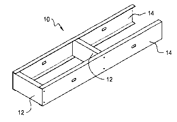
[0004] Figure I shows an isometric view of the framing system of the present
invention.
[0005] Figure 2 shows an exploded isometric view of the invention of Figure 1.
[0006] Figure 3 shows an isometric view of the stud of the invention of Figure
1.
[0007] Other features and advantages of the invention will become apparent to
those skilled
in the art upon review of the following detailed description, claims and
drawings in
which like numerals are used to designate like features.
DETAILED DESCRIPTION OF THE INVENTION
[0008] The invention may be embodied in various forms. Referring to the
Figures wherein
like numerals are used to designate like features, there is depicted in Figure
I a
framing system 10 of the present invention. The framing system 10 includes a
plurality of studs 12 and a plurality of track 14 that are mounted together to
make a
portion of the underlying frame for a building, such as a storage building,
shed,
shelter, house or other similar buildings. The framing system 10 is
particularly useful
as the frame underlying the floor of a storage building or shed. The
individual studs
12 and track 14 are further depicted in Figure 2.
[0009] Referring to Figure 3, the stud 12 defines a longitudinally extending
body 16 having
opposing ends 18, 20 and opposing sides 22, 24. Extending outwardly from the
sides
22, 24 of the body 16 are opposing flanges 26. The flanges extend outwardly at
approximately an angle of 90 degrees from the body 16. Located at the ends 28
of the
flanges 26 are second opposing flanges 30 that extend outwardly at
approximately an
angle of 90 degrees from the flanges 26. As depicted, the flanges 30 extend
parallel
to the body 16 and toward the longitudinal center of the body 16. The body 16
and
2

CA 02541673 2006-04-05
WO 2005/035891 PCT/US2004/034162
flanges 26, 30 form a stud that has a C-shaped cross section. One of skill in
the art
will understand that other similar stud shapes and configurations are
possible.
[0010] Located at the ends 18, 20 of the stud 12 are a plurality of holes or
slots 29 positioned
linearly and extending transversely across the body 16 of the stud. Also
located at the
ends 18, 20 are foldable end flaps 31 that, as depicted, are foldable along
the plurality
of holes 29. The foldable flaps define a mounting surface on which the track
14 may
be attached and also serve as a stiffener for the study 12. As depicted, the
track 14
may be mounted to the stud 12 at various positions along the track 14.
[0011] Referring to Figure 2, the track 14 includes a longitudinally extending
body 32 with
opposing ends 34, 36 and opposing sides 38, 40. Extending outwardly from the
opposing ends 34, 36 are opposing flanges 42. The opposing flanges 42 extend
outwardly at an angle of approximately 90 degrees from the body 32. Mounting
holes 44 are positioned along the body 32 of the track to permit the mounting
of the
track 14 to the stud 12 and specifically to the end flaps 31 of the study 12.
As is
known in the art, fasteners or rivets or the like may be used to mount the
track 14 to
the stud 12. Again, one skilled in the art will understand that other shapes
and
configurations of the track are possible.
[0012] The stud 12 and track 14 are preferably made of flat rolled carbon
steel with a
galvanized zinc coating for added corrosion resistance. It should be
understood by
those skilled in the art that other suitable materials may be used with the
present
invention depending on the application and the environment in which the
framing
system is to be used.
[0013] While the invention has been described with respect to specific
examples including
presently preferred modes of carrying out the invention, those skilled in the
art will
appreciate that there are numerous variations and permutations of the above
described
3

CA 02541673 2006-04-05
WO 2005/035891 PCT/US2004/034162
systems and techniques that fall within the spirit and scope of the invention
as set
forth in the appended claims.

Dessin représentatif
Une figure unique qui représente un dessin illustrant l'invention.
États administratifs

2024-08-01 : Dans le cadre de la transition vers les Brevets de nouvelle génération (BNG), la base de données sur les brevets canadiens (BDBC) contient désormais un Historique d'événement plus détaillé, qui reproduit le Journal des événements de notre nouvelle solution interne.

Veuillez noter que les événements débutant par « Inactive : » se réfèrent à des événements qui ne sont plus utilisés dans notre nouvelle solution interne.

Pour une meilleure compréhension de l'état de la demande ou brevet qui figure sur cette page, la rubrique Mise en garde , et les descriptions de Brevet , Historique d'événement , Taxes périodiques et Historique des paiements devraient être consultées.

Historique d'événement

Description Date
Le délai pour l'annulation est expiré 2008-10-06
Demande non rétablie avant l'échéance 2008-10-06
Réputée abandonnée - omission de répondre à un avis sur les taxes pour le maintien en état 2007-10-09
Lettre envoyée 2007-05-18
Inactive : Transfert individuel 2007-04-04
Inactive : Page couverture publiée 2006-06-13
Inactive : Lettre de courtoisie - Preuve 2006-06-13
Inactive : Notice - Entrée phase nat. - Pas de RE 2006-06-09
Demande reçue - PCT 2006-05-04
Exigences pour l'entrée dans la phase nationale - jugée conforme 2006-04-05
Demande publiée (accessible au public) 2005-04-21

Historique d'abandonnement

Date d'abandonnement Raison Date de rétablissement
2007-10-09

Taxes périodiques

Le dernier paiement a été reçu le 2006-09-27

Avis : Si le paiement en totalité n'a pas été reçu au plus tard à la date indiquée, une taxe supplémentaire peut être imposée, soit une des taxes suivantes :

  • taxe de rétablissement ;
  • taxe pour paiement en souffrance ; ou
  • taxe additionnelle pour le renversement d'une péremption réputée.

Veuillez vous référer à la page web des taxes sur les brevets de l'OPIC pour voir tous les montants actuels des taxes.

Historique des taxes

Type de taxes Anniversaire Échéance Date payée
Taxe nationale de base - générale 2006-04-05
TM (demande, 2e anniv.) - générale 02 2006-10-06 2006-09-27
Enregistrement d'un document 2007-04-04
Titulaires au dossier

Les titulaires actuels et antérieures au dossier sont affichés en ordre alphabétique.

Titulaires actuels au dossier
ALLIED TUBE & CONDUIT CORPORATION
Titulaires antérieures au dossier
DAVID D. PLUEARD
MICHAEL A. MEEK
Les propriétaires antérieurs qui ne figurent pas dans la liste des « Propriétaires au dossier » apparaîtront dans d'autres documents au dossier.
Documents

Pour visionner les fichiers sélectionnés, entrer le code reCAPTCHA :


Pour visualiser une image, cliquer sur un lien dans la colonne description du document. Pour télécharger l'image (les images), cliquer l'une ou plusieurs cases à cocher dans la première colonne et ensuite cliquer sur le bouton "Télécharger sélection en format PDF (archive Zip)" ou le bouton "Télécharger sélection (en un fichier PDF fusionné)".

Liste des documents de brevet publiés et non publiés sur la BDBC .

Si vous avez des difficultés à accéder au contenu, veuillez communiquer avec le Centre de services à la clientèle au 1-866-997-1936, ou envoyer un courriel au Centre de service à la clientèle de l'OPIC.


Description du
Document 
Date
(aaaa-mm-jj) 
Nombre de pages   Taille de l'image (Ko) 
Dessins 2006-04-05 2 30
Description 2006-04-05 4 126
Revendications 2006-04-05 2 46
Abrégé 2006-04-05 1 59
Page couverture 2006-06-13 1 31
Rappel de taxe de maintien due 2006-06-12 1 110
Avis d'entree dans la phase nationale 2006-06-09 1 192
Demande de preuve ou de transfert manquant 2007-04-10 1 101
Courtoisie - Certificat d'enregistrement (document(s) connexe(s)) 2007-05-18 1 107
Courtoisie - Lettre d'abandon (taxe de maintien en état) 2007-12-04 1 175
PCT 2006-04-05 2 66
Correspondance 2006-06-09 1 26