Note : Les descriptions sont présentées dans la langue officielle dans laquelle elles ont été soumises.
CA 02541773 2006-04-05
WO 2005/032325 PCT/IL2004/000919
APPARATUS FOR SPINAL FIXATION OF VERTEBRAE
FIELD OF THE INVENTION
The present invention relates to the field of devices and methods for
facilitating the performance of surgery on a number of vertebrae in a single
procedure, and especially using robotic execution of the procedure, computer
assisted techniques, or frame-aligned manual surgery.
BACKGROUND OF THE INVENTION
In a conventional surgical operation, the surgeon operates on an organ
using his visual and tactile senses in order to locate his hand and
the'surgical tool
in the correct position. In Computer Assisted Surgery (CAS) however, the
motion of the surgical tool is generally determined by a pre-operative plan,
with
the actual operating location being pre-planned using pre-operative X-ray, CT,
MRI or other images. During the operation, it is necessary to transfer this
planning information to the operation site, generally by mutually referencing
the
coordinate system of the patient, the position of the surgical tool and the
data
provided by the pre-operative plan. This is known as a registration procedure.
It is therefore important to provide the computer with accurate information
concerning the patient position relative to the navigation/robotic system.
This is
accomplished in contemporary CAS devices by either holding the body part on
which the operation is being performed, in a fixed position following the
registration process, or by attaching a' dynamic referencing device which
moves
with the body part being operated on, and compensates for undesired motion by
means of dedicated tracking software.
In spinal operation CAS procedures, if the procedure is to be performed
on more than one vertebra, it is necessary, according to prior art methods, to
affix
dynamic referencing sensors at each level of the spine, or even on each
vertebra,
so that relative motion between different regions of the spine or even between
CA 02541773 2011-08-03
2
different vertebrae can be detected and compensated for. Alternatively, all of
the
vertebra to be operated on are fixed to a stationary frame to ensure well-
defined
positions. Both of these alternatives are complex and inconvenient procedures.
There therefore exists an important need to provide a method of enabling
CAS to be performed on several vertebrae in a single procedure, by means of a
simple apparatus.
Additionally, when surgery is to be performed to correct or treat
conditions related to spinal curvature, according to prior art methods the
surgeon
has generally used visual means for estimating the position of the vertebrae
at
io different levels of the back. Such visual estimation, whether based on
manual
manipulation of the operating tools, or CAS guidance thereof, is potentially
inaccurate and highly dependent on the surgeon's skill. There therefore also
exists a need to provide a reference method for providing the surgeon with
information about the relative location of vertebrae over the whole length of
the
spine.
SUMMARY OF THE INVENTION.
According to the present invention, there is provided a system for use in
surgery on vertebrae of the spine of a subject, said system comprising:
a bridge attached at least at one end to a first vertebra in said spine of the
20 subject; and
a surgical robot mounted on said bridge, said robot being adapted to enable
the performance of a surgical procedure on at least said first vertebra,
wherein said bridge can move with movement of the spine of the subject, such
that movement of the spine does not affect the position of said robot relative
to said
at least one vertebra, and wherein said bridge comprises a number of
CA 02541773 2011-08-03
2a
predetermined locations adapted for positioning said robot such that surgery
may
be performed on a plurality of vertebrae in a single procedure.
According to the present invention, there is also provided a system for use in
surgery on the vertebrae of the spine of a subject, said system comprising:
a bridge assembly comprising:
at least a first spinal bridge section attached at least at one end to a
first vertebra in said spine of the subject;
at least a second spinal bridge section having two ends, one of said
ends being attached to said at least a first spinal bridge section, and a
second of
said ends being attached to either of the pelvic bone structure of the subject
and
the skull of the subject; and
a surgical robot mounted on said bridge assembly, said robot being adapted
to enable the performance of surgical procedures on a plurality of vertebrae,
wherein said bridge assembly moves with movement of the spine of the subject,
such that movement of the spine does not affect the position of said robot
relative
to said plurality of vertebrae, and wherein at least one of said bridge
sections of
said bridge assembly comprises a number of predetermined locations adapted for
positioning said robot such that said surgery may be performed on said
plurality of
vertebrae in a single procedure.
Other aspects, objectives, embodiments, variants and/or advantages of the
present invention, all being preferred, are briefly summarized hereinbelow.
Indeed, there is thus provided, according to various preferred embodiments of
the
present invention, novel frame devices for use in fixing a number of vertebrae
together into positions which are uniquely defined relative to the frame. Such
fixation is especially useful in two applications of spinal surgery:
(i) as a reference frame for Computer Assisted Surgery procedures
performed on a number of vertebrae of the spine in one procedure, either
using manual navigation and a tracking system to follow the position of 'the
CA 02541773 2011-08-03
2b
surgeon's tools relative to the operated vertebrae, or by using a
pre-programmed robot to perform the surgery.; and
(ii) as a reference frame for use in performing surgical procedures at
locations along the entire length of the spine of a subject, or a major part
thereof, when it is necessary to provide a reference for the alignment of
major lengths of the spine or of all of the spine.
CA 02541773 2006-04-05
WO 2005/032325 PCT/IL2004/000919
3
According to a first preferred embodiment of the present invention, there
is provided a reference bridge that fixes several vertebra together to
generate a
single frame of reference for all of those vertebrae. This bridge differs from
prior
art vertebrae fixing devices in that although it is fixed above the spine and
is
fixed relative to the vertebrae, it is allowed to move in space as a single
unit with
movement of the spine relative to the operating table. A dynamic referencing
sensor, a miniature robot or a passive measuring arm operating as a mechanical
digitizer, can be attached to this reference bridge, and since each of the
relevant
vertebrae are affixed to the bridge, a single registration procedure can be
used to
define the relative position and orientation of each of the vertebra and of
the
frame itself, relative to the operation planning environment, whether a
preoperative CT or MRI image, or an intra-operative X-ray fluoroscopic image,
or any other. This thus obviates the prior art need either for individual
registration of each vertebra, or for fixing of all of the vertebrae relative
to the
operating table.
The reference bridge is generally fixed only to a limited number of
vertebrae, such that only those vertebrae fixed by some means to the bridge
can
be considered as having a positively defined position relative to the bridge.
However, since the relative allowed motion between neighboring vertebrae is
small, even unattached vertebrae next to, or close to, vertebrae attached to
the
bridge, can also be considered to have reasonably well defined positions
relative
to the bridge. The required precision of the surgical procedure to be
performed
determines to what extent the positions of such unattached "neighboring
vertebrae" can be assumed to be sufficiently precisely known.
It is to be understood that terms such as "above the spine" or "above a
vertebra", or similar, as used in this application, and as claimed, are not
meant to
define a position in absolute space, but rather to indicate a general
disposition
relative to the spine or vertebrae. Since the usual position for performing
spinal
surgical procedures is when the subject is supine, the term "above" is used to
describe this general disposition, though is not meant to limit the invention
to the
use of mutually vertical relative positions.
CA 02541773 2011-08-03
4
Once their relative position is known, the vertebrae can then be accurately
operated upon, either using a navigation system or a bone mounted or bridge
mounted robot. The preferred use of a bone mounted or bridge mounted robot is
an advantageous embodiment, because it obviates the need to know where the
vertebrae are relative to the environment, being concerned only with the
relative
position of the vertebrae to each other and to the bridge, since the robot
position
is known relative to either of them.
According to another preferred embodiment of the present invention, the
bridge is used with a navigation system external to the bridge, in which the
bridge ensures that the referencing to each vertebrae is known, not only
relative
to each other vertebra, but also absolutely in space, and hence relative to
the
external navigation system. In such embodiment, a tracking system is used to
ensure correct positioning of the surgeon's tools relative to the bridge and
hence
to each vertebra.
When utilized for executing the first group (i) of applications mentioned
hereinabove, the bridge according to these preferred embodiments of the
present
invention, is operative in the fixation of the positions of several, generally
adjacent or closely spaced vertebra to the bridge. When utilized for executing
the
second group (ii) of applications mentioned hereinabove, the bridge preferably
takes the form of a long frame extending in its maximum configuration, from
the
pelvis to the skull, preferably with fixation at the skull and the pelvis, and
at
selected vertebral points between them. According to further preferred
embodiments of the present invention, the long frame bridge can extend, if not
over the whole length of the spine, then at least over large parts thereof,
such as
from the skull to the bottom of the thoracic level, or from the pelvis to the
bottom
of the cervical level. In any of the long frame embodiments, the bridge is
preferably divided into - several parts, preferably at least one central
section
generally covering the thoracic section of the spine, a lower section covering
the
lumbar region, and an upper section covering the cervical section.
CA 02541773 2006-04-05
WO 2005/032325 PCT/IL2004/000919
There are several indications in which the present invention can be
advantageously applied, the indications being listed according to the spinal
region of their application:
A. Surgical Indications for the Cervical Region
1.Atlantoaxial Instability, (C1-C2 Injuries)-Magerl technique of
transarticular Cl-C2 screw fixation.
2. Radiculopathy, when present, due to entrapment of an exiting nerve
root within a collapsed neuroforamen.
3. Syndrom a vertebralis due to segmental cervical spine instability.
4. Fractures of vertebral bodies.
5. Spinal vertebral body tumor with adjacent vertebral body fusion.
6. Failed decompressive. operations with syndrome of cervical spine
instability (status post laminectomy).
B. Surgical Indications for the Thoracic and Lumbar Regions
1. Mechanical back pain.
2. Radiculopathy, when present, is due to entrapment of an exiting nerve
root within a collapsed neuroforamen.
3. Spondylolisthesis.
4. Fractures of vertebral bodies
5. Spinal vertebral body tumor with adjacent vertebral body fusion.
6. Failed previous fusion (pseudoarthrosis).
7. Failed decompressive operations with syndrome of lumbar spine
instability.
8. Scoliosis correction.
There is therefore provided in accordance with a preferred embodiment of
the present invention, a bridge for use in surgery on the vertebrae of the
spine of
a subject, the bridge comprising (i) a first support member for attaching at
one
end to a first vertebra in the spine of the subject, (ii) at least a second
support
member for attaching at one end to a second bone of the subject, and (iii) a
cross
member attached to the first and second support members at positions remote
CA 02541773 2006-04-05
WO 2005/032325 PCT/IL2004/000919
6
from the ends of the support members attached to the subject, such that the
cross
member is positioned proximate the spine of the subject. The second bone of
the
subject may preferably be a second vertebra of the subject's spine, the
subject's
skull, or the subject's pelvic bone. In any of the above mentioned embodiments
of the present invention, the bridge is preferably. such that it is free to
move with
movement of the spine of the subject. Furthermore, in any of the above-
mentioned bridge embodiments, the first support member may preferably be
attached to the first vertebra in the spine of the subject by means of a bone
clamp,
or it may be a K-wire.
According to a further preferred embodiment, the bridge may also
comprise at least one additional support element for attaching the cross
member
to at least one additional vertebra of the spine, such that the first
vertebra, the
second bone and the at least one additional vertebrae have fixed positions
relative
to the bridge. The at least one additional support element may preferably be a
K-wire.
In accordance with still another preferred embodiment of the present
invention, in the above-described bridge, the cross member may preferably be
adapted to accommodate a surgical robot, such that the robot can perform
surgical procedures on at least one of the vertebrae. Preferably, the surgical
robot
can be accommodated at any of a plurality of predefined positions along the
cross
member, such that the robot can perform surgical procedures on a plurality of
the
vertebrae. In such a case, the robot can preferably perform these surgical
procedures on a plurality of the vertebrae with a single registration process.
Alternatively and preferably, a surgical robot may be attached to one of the
vertebrae, such that the robot can perform surgical procedures on at least one
of
the vertebrae. These surgical procedures can preferably be performed on a
plurality of the vertebrae with a single registration process.
According to still another preferred embodiment of the present invention,
the bridge can be provided with a navigational position probe associated with
a
computer assisted surgery system, such that the position of the bridge and of
the
vertebrae are known to the system.
CA 02541773 2006-04-05
WO 2005/032325 PCT/IL2004/000919
7
There is further provided in accordance with yet another preferred
embodiment of the present invention, a bridge assembly for use in surgery on
the
spine of a subject, the bridge assembly comprising (i) at least a first spinal
bridge
section comprising at least two support members, each of the support members
being attached to one vertebra of the spine, and a cross member connecting the
support members and attached thereto at positions remote from the vertebra
attachment ends of the support members, and (ii) at least a second spinal
bridge
section having two ends, one of the ends being attached to the at least a
first
spinal bridge section, and a second of the ends being attached by support
members to either the pelvic bone structure of the subject or the skull of the
subject, wherein the support members are such that the bridge assembly is
positioned proximate the vertebrae of the spine. In accordance with still
another
preferred embodiment of the present invention, in such a bridge assembly, the
at
least a second spinal bridge section may comprise two spinal bridge sections,
one
attached at its second end to the pelvic bone structure of the subject and the
other
attached at its second end to the skull of the subject, such that the bridge
assembly is positioned proximate vertebrae along the entire length of the
spine.
In such a case, the bridge comprises a lumbar section, a cervical section and
at
least one thoracic bridge section. In any of the above mentioned embodiments
of
the present invention, the bridge assembly is preferably such that it is free
to
move with movement of the spine of the subject.
In accordance with still another preferred embodiment of the present
invention, in the above-described bridge assembly, the bridge sections may
preferably be adapted to accommodate a surgical robot such that the robot can
perform surgical procedures on at least one of the vertebrae. Preferably, the
surgical robot can be accommodated at any of a plurality of predefined
positions
along the bridge sections of the bridge assembly, such that the robot can
perform
the surgical procedures on a plurality of the vertebrae. In such a case, the
robot
can preferably perform these surgical procedures on a plurality of the
vertebrae
with a single registration process. Alternatively and preferably, a surgical
robot
may be attached to one of the vertebrae, such that the robot can perform
surgical
CA 02541773 2011-08-03
8
procedures on at least one of the vertebrae. These surgical procedures can
preferably be performed on a plurality of the vertebrae with a single
registration
process.
According to still another preferred embodiment of the present invention,
the bridge assembly can be provided with a- navigational position probe
associated with a computer assisted surgery system, such that the position of
any
part of the bridge assembly and of the vertebrae are known to the system.
BRIEF DESCRIPTION OF THE DRAWINGS
The present invention will be understood and appreciated more fully from
the following detailed description, taken in conjunction with the drawings in
which:
Fig. 1 is a schematic illustration of the whole of a subject's spine, showing
two reference bridges, constructed and operative according to various
preferred
embodiments of the present invention, namely, a full-spine bridge assembly
covering the whole length of the spine, and a short bridge covering several
vertebrae of the lumbar section of the spine;
Fig. 2 illustrates schematically a close-up view of a lumbar section of a
subject's spine, showing the short bridge of Fig. 1 connecting a number of
lumbar vertebrae together;
. . Fig. 3 is a schematic, illustration of a lumbar section of subject's
spine,
showing a bridge, similar in function to that of the embodiment of Fig. 2, but
constructed and operative according to another preferred embodiment of the
present invention;
Fig. 4 is a schematic illustration of a lumbar section bridge, showing the
component parts for anchoring the lumbar section to the subject's pelvis;
CA 02541773 2006-04-05
WO 2005/032325 PCT/IL2004/000919
9
Fig. 5 is an alternative preferred embodiment of a lumbar section bridge,
similar to that shown in Fig. 4; and
Figs. 6 and 7 schematically show preferred embodiments of the whole
spine bridge assembly described in the embodiments of Figs. 4 and 5, but with
a
miniature surgical robot attached thereto; Fig. 6 shows the robot mounted on
the
thoracic section of the bridge, while Fig. 7 shows the robot mounted on the
lumbar section of the bridge.
DETAILED DESCRIPTION OF PREFERRED EMBODIMENTS
Reference is now made to Fig. I , which is a schematic illustration of a
model of the whole of a subject's spine, showing two reference bridges,
constructed and operative according to various preferred embodiments of the
present invention, for facilitating the performance of surgical procedures on
the
spine 10 of the subject. The illustration shows a first reference bridge 12
connecting a number of lumbar vertebrae 14 for enabling treatment of several
vertebrae in a single procedure, as mentioned in application (i) hereinabove,
and
a second reference bridge assembly 16, composed of several-bridge sections,
preferably connected to a number of vertebrae 18 along the entire length of
the
spine, as well as to the skull 20 and the pelvis 22, as mentioned in
application (ii)
hereinabove. It is to be understood that the two bridges shown can generally
be
used either as one connected system with no mutual relative motion, or
separately and independently. Each of these embodiments is now described in
more detail in the drawings to follow.
Reference is now made to Fig. 2, which illustrates schematically a view of
a lumbar section of a subject's spine, showing a bridge, constructed and
operative according to a first preferred embodiment of the present invention,
connecting a number of lumbar vertebrae together. Though this embodiment is
illustrated in connection with the lumbar vertebrae, it is to be understood
that it is
applicable to groups of vertebrae at any level of the back. In the preferred
embodiment illustrated, the bridge 12, comprising a cross member 30 with
CA 02541773 2011-08-03
referencing holes 32, and two vertical support arms 34, is connected to the
spinous processes of four adjacent vertebrae 14. When applied to a real
subject,
the attachment is preferably performed minimally invasively, through small
incisions in the subject's skin and back tissue (not shown in any of the
drawings).
Though the cross members 30 are shown as simple flat elements in most of the
illustrated embodiments of the present application, it is to be understand
that they
could also be of any other preferred form, such as rails, or angled profiles,
or
even a double strips, and the term cross member as claimed in the present
application, is thuswise to be understood. Two preferred methods of attachment
10 are shown in Fig. 2, the support arms 34 being preferably attached by means
of
clamps 36 onto the spinous processes of the outer pair of vertebrae, while the
inner vertebrae are preferably connected to the cross member 30 by means of
1.5-2mm K-wires 38 attached to their corresponding spinous processes.
Once the bridge has been mounted onto the vertebrae to be treated, the
cross member 30 constitutes a platform disposed close to and above the spine,
and which has a fixed position relative to each of the vertebrae connected
thereto,
and moves in absolute space together with the vertebrae. As described
hereinabove, a preliminary registration procedure, as known in the art, can be
performed to define the relative position and orientation of each of the
vertebra
relative to the frame itself, by means of dynamic referencing sensors, or a
passive
measuring arm operating as a mechanical digitizer. Once this has been done,
the
position of each of the vertebrae is known relative to the bridge, and if
suitable
pre-registration fiducials have been used, the position also of the bridge
itself
relative to the operation planning environment, whether a preoperative CT or
MRI image, or an intra-operative X-ray fluoroscopic image, or any other image.
According to one preferred method of use of the bridge of this embodiment, a
CA 02541773 2011-08-03
11
miniature surgical robot, such as that described in US Patent No. 6,837,892,
to one
of the inventors of the present application, may be attached to one or more of
the
referencing holes 32. Such a miniature robot is then able to utilize the
registration
information to perform accurately positioned procedures, such as screw hole
drilling, on each of the vertebrae in succession, regardless of whether the
subject
moves between the procedures on the successive vertebrae. This thus enables
such procedures to be performed more conveniently and comfortably than by
means of prior art methods, where either each vertebra is registered and
operated
on independently, or alternatively, if they are connected preoperatively, the
subject
is fixed relative to the operating table to render the connected vertebrae
immobile.
According to another preferred procedure, the operation may be
performed by a surgeon using hand-held tools, and an external tracking system
used to relate the position of these tools to the position of the bridge and
each of
the vertebrae, and to the operation environment, whether predetermined by
preliminary imaging, or determined intra-operatively.
Reference is now made to Fig. 3, which is a schematic illustration of a
lumbar section of subject's spine, showing a bridge, similar in function to
that of
the embodiment of Fig. 2, but constructed and operative according to another
preferred embodiment of the present invention. Features common to those of
Fig.
2 are labeled with the same reference characters. The bridge shown in Fig. 3
differs from that shown in Fig. 2 in that the cross member 40 of the bridge
has a
series of flat surfaces 42, with mounting holes 44 which are located to match
the
mounting holes of the base 48 of a miniature surgical robot 46, of the type
shown
below in Figs. 6 and 7. The robot is shown in Fig. 3 ready for mounting onto
the
center position of the bridge. Such a preferred mounting method makes it
particularly simple to move the robot from position to position when needed,
CA 02541773 2011-08-03
11a
while maintaining the accuracy of the registration. Though the robot in Fig. 3
is
shown without any operating tools attached to its working platform 50, it is
to be
understood that any such tools may preferably be attached thereto, such as is
described in the above mentioned US Patent No. 6,837,892.
The bridge of Fig. 3 also shows another preferred method of attachment to
the vertebrae, whereby the center of the bridge is attached by means of a
clamp,
CA 02541773 2006-04-05
WO 2005/032325 PCT/IL2004/000919
12
and the outer ends by means of K-wires attached to the spinous processes of
the
pouter vertebrae.
Reference is now made back to Fig. 1, in order to describe details of the
construction and operation of the whole-spine bridge, according to another
preferred embodiment of the present invention. The bridge, according to this
embodiment, can preferably be divided into three separate joined component
sections - a lumbar section, a thoracic section and a cervical section. It is
to be
understood however, that this division is only one convenient manner of
constructing such a bridge, and the present invention is not meant to be
limited
thereby. Other preferred constructions can also be envisaged, and even partial
spine bridges, where not all three sections of the spine are included, such as
a
lower back bridge covering from the thoracic section down to the pelvis, or an
upper back bridge, covering from the thoracic section up to the skull.
The thoracic section 76 of the bridge is connected at its lower end to the
lumbar section 60, and at its upper end by means of one or more clamps 78 to
the
spinous processes of one or more chosen vertebrae from the thoracic spine
region. Alternatively and preferably, though not shown specifically in Fig. 1,
one
or more 1.5-2 mm K-wires are drilled into one or more chosen vertebrae from
the
thoracic spine region, in the same manner as K-wires are shown in Fig. 2 for
use
with the lumbar vertebrae. As will be described in more detail below, a
sliding
carriage is preferably attached to the bridge, and can be moved to any desired
position along the thoracic section of the bridge, and rigidly locked
preferably by
means of a thumbscrew above the region of interest. A robotic system or a
dynamic referencing probe can be attached to the sliding carriage, and
positioned
at any of several defined locations down the thoracic spine, in order to reach
any
desired point along the thoracic spinal region. The miniature surgical robot
can
preferably be mounted on the platform of the carriage, in a manner similar to
that
shown in Figs. 6 and 7 hereinbelow.
At the top end of the spine, the cervical section of the bridge 80 is shown.
A halo ring 81 or another commonly used fixing device, is rigidly attached on
the
subject's skull 20. It is to be understood that this aspect of the invention
is
CA 02541773 2006-04-05
WO 2005/032325 PCT/IL2004/000919
13
applicable whether the fixing device is attached directly to the skull bones,
such
as by screws penetrating into the bone structure, or whether the fixing device
is
attached to the skull by means of a clamping mechanism which holds the fixing
device rigidly relative to the skull by applying pressure to the skull through
the
skin, but without penetrating the skin. In this application, both of these
types of
devices are described and claimed as being "attached" on the subject's skull.
The
upper end of the cervical section 80 of the bridge is preferably supported by
attachment to the halo ring 81. The lower end is supported either by
attachment
to the upper end of the thoracic section 76 of the bridge, or by means of a
clamp
or one or more K-wires to spinous processes suitably located near the lower
cervical region. As with the lumbar 60 and thoracic bridge 76 sections, a
sliding
carriage is preferably attached to the bridge, and can be moved to any desired
position along the thoracic section of the bridge, and rigidly locked above
the
region of interest. A robotic system or a dynamic referencing probe can be
attached to the sliding carriage, and can thus be positioned at any of several
defined locations in order to reach any desired point in the cervical spinal
region.
The miniature surgical robot can preferably be mounted on the platform of the
carriage, in a manner similar to that shown in Figs. 6 and 7 hereinbelow.
The cervical section of the bridge is preferably profiled to have the same
approximate shape 83 as the cervical lordosis, such that the operating point
of the
robot mounted on the carriage remains close to the point of operation on the
subject's spine.
Although in the preferred embodiment of the spinal bridge shown in Fig.
1, the thoracic section 76 of the bridge is shown anchored to the ends of the
cervical 80 and lumbar 60 sections, it is to be understood that the invention
is not
meant to be limited thereby, but that any suitable connection scheme may be
used, whereby the ends of each section of the bridge are firmly connected to
their
neighboring section's ends, where applicable, such that all of the sections of
the
bridge form one rigid structure generally parallel to the line of the spine,
and are
also firmly disposed relative to the vertebrae of the spine. Thus, for
example,
according to another preferred embodiment of the present invention, either or
CA 02541773 2006-04-05
WO 2005/032325 PCT/IL2004/000919
14
both ends of the thoracic section could preferably be connected directly to
vertebrae, and the cervical and lumbar sections attached to the thoracic
section.
Furthermore, although the invention has been described using three sections of
the whole-spine bridge, it is to be understood that the invention is not meant
to be
limited thereby, but that embodiments using two adjacent sections of the three
described are also understood to be included as preferred embodiments of the
present invention.
Whole spine bridges have been used previously for Halofemoral
longitudinal and pelvic traction for the correction of spinal deformity. The
spinal
bridges of the present invention differ in that they are adapted for use in
surgical
procedures performed on the spine, generally to correct spinal deformities,
such
as scoliotic deformity. Use of the spinal bridge of the present invention
improves
the anatomical relationships between vertebrae on which procedures are being
performed, such as by improving the accuracy with which screw insertion is
made into the pedicles for attaching inserts for correcting such deformities.
Additionally, the present invention may also be advantageous for providing
increased accuracy in robotic screw insertion through reduction of mutual
movement of adjacent vertebrae, since such mutual movement may result in
degraded screw insertion accuracy. Furthermore, the use of the whole spine
bridge of the present invention improves the accuracy of many surgical
procedures performed using it, whether drilling, sawing, milling or even
simple
guidance of a surgical tool relative to the vertebrae of the whole spine,
whether
applied robotically or manually by the surgeon, such that the procedure is
accurately performed relative to all of the vertebrae to be operated on.
Reference is now also made to Figs. 4 and 5, which show further details of
the lower end of the whole spine bridge, and which are to be viewed together
with the details shown in Fig. 1. Fig. 4 is a schematic illustration of the
lumbar
section of the bridge, showing the component parts for anchoring this section
to
the subject's pelvis. Fig. 5 is a schematic illustration of an alternative
embodiment to that shown in Fig. 4, of the lumbar section of the bridge. The
lumbar bridge section 60 preferably comprises two nails 62 with screwed ends,
CA 02541773 2006-04-05
WO 2005/032325 PCT/IL2004/000919
inserted into the spina iliaca posterior superior on both right and left sides
of the
subject. A bar 66 is preferably attached to both screwed nails 62, in order to
generate a rigid connection between the two nails, to serve as a base anchor
for
the lumbar section 60 of the spinal bridge. The upper end of the lumbar
section
of the bridge is preferably attached to a spinous process of one of the upper
lumbar vertebrae, either by means of a clamp 68 as shown in Fig. 1, or by
means
of a K-wire 70, shown in Fig. 4, drilled into such a suitably located spinous
process in the lumbar spine region. The lumbar bridge section and its
component
parts are preferably attached to each other by means of adjustable fittings,
such
that the disposition of the bridge relative to the spine can be performed with
maximum flexibility to suit individual subjects.
Attached to the bridge is a sliding carriage 72, that can be moved to any
desired position along the lumbar section of the bridge, and rigidly locked by
means of a thumbscrew 74 above the lumbar spine region of interest. A robotic
system or a dynamic referencing probe can be attached to the sliding carriage,
and thus positioned at several defined orientations in order to reach any
desired
location along the lumbar spine. The miniature surgical robot or a dynamic
referencing sensor can preferably be mounted on the platform of the carriage,
in a
manner similar to that shown in Figs. 6 and 7 hereinbelow.
Reference is now made to Fig. 5, which schematically illustrates an
alternative and preferable arrangement for the construction of the lumbar
section
of the bridge, and for anchoring this section to the subject's pelvis. Parts
having
the same function as those shown in the embodiment of Fig 4, are labeled with
the same reference characters, even though the structural form may be
different.
The sliding carriage 72 differs from that in Fig. 4 in that it has an offset
table 75
on which a miniature robot is preferably mounted, such an offset table
providing
better lateral access to the vertebrae, such as is advantageous in the
performance
of translaminar or transfacet fusion procedures. Additionally, the bridge
length
adjustment is performed at the pelvic end and not at the upper end. The
mounting
block 71 at the top end can be adapted to be fixed to the spine either by
means of
CA 02541773 2011-08-03
16
a K-wire, as shown in Fig. 4, or by means of a spinal process clamp, as shown
in
Fig. 1.
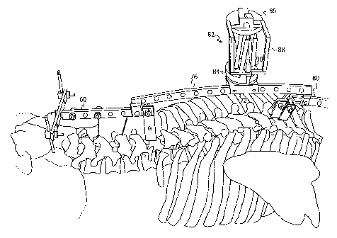
Reference is now made to Figs. 6 and 7, which schematically show
preferred embodiments of the whole spine bridge described in the embodiment of
Fig. 1, also showing attached thereto, a miniature surgical robot 82 of the
type
described in US Patent No. 6,837,892.
In Fig. 6, the robot 82 is shown attached by its base 84 to the adjustable
platform 72 on the thoracic section 76 of the bridge. The top plate 86 of the
preferred miniature robot shown is the surface whose motion is controlled by
the
robot actuators. To that surface is preferably attached a tool frame 88, which
in
the embodiment shown, carries a drill guide 90 for positioning the surgeon's
drill
accurately where required by the operation procedure. In Fig. 7, according to
another preferred embodiment of the present invention, the robot 82 is shown
attached by its base 84 to the adjustable platform 72 on the lumbar section 76
of
the bridge. The top plate 86 of the robot shown is the surface whose motion is
controlled by the robot actuators, and to that surface is preferably attached
a tool
frame 88, which in the embodiment shown, carries a drill guide 90 for
positioning the surgeon's drill accurately when so required in the operation
procedure.
It is appreciated by persons skilled in the art that the present invention is
not limited by what has been particularly shown and described hereinabove.
Rather the scope of the present invention includes both combinations and
subcombinations of various features described hereinabove as well as
variations
and modifications thereto which would occur to a person of skill in the art
upon
reading the above description and which are not in the prior art.