Note : Les descriptions sont présentées dans la langue officielle dans laquelle elles ont été soumises.
CA 02541915 2006-04-05
ELECTRIC OVEN
BACKGROUND OF THE INVENTION
Field of the Invention
[0001] The present invention relates to an electric oven, and
more particularly, to a heater cooling structure that can
intensively cool only a seal portion of a halogen heater using
the heat conduction.
Description of the Related Art
[0002] An electric oven is generally used for baking or
roasting food by heating the food using heat and steam generated
from the food and confined in the oven. Therefore, the food can
be cooked with a good taste without being burnt or hardened by
contraction, which caused when the food is directly roasted by
fire.
[0003] A typical electric oven includes a cavity in which
food is loaded and a door for opening and closing the oven to
load and withdraw the food in and from the cavity. A heat source
such as a heater is placed in the cavity.
1
CA 02541915 2006-04-05
[0004] The heater includes an upper infrared heater mounted
on an upper portion of the cavity, a lower heater mounted on a
lower portion of the cavity to increase an operation temperature
of the cavity and a convection heater mounted on a rear portion
of the cavity to bake the food. A fan is provided around the
convection heater to circulate fluid in the cavity.
[0005] The electric oven heats the food by transferring
thermal energy to the food by turning on one or more of the upper,
lower and convection heaters or by alternately turning on them.
[0006] When the heater is a sealed quartz tube heater such as
the halogen heater, the seal portion to which a lead wire is
connected is formed by compressing the glass. When a temperature
of the seal portion increases to a predetermined level (about
250 C, a gap is created due to the thermal expansion between the
metal and glass and thus air may be introduced into the quartz
tube through the gap, thereby reducing the service life of an
inner filament of the quartz tube.
[0007] To solve the problem, a cover is provided with a
plurality of holes to cool the seal portion.
[0008] However, although the forming of the holes on the
2
CA 02541915 2006-04-05
cover may have an advantage of cooling the seal portion, thermal
energy may leak through a gap created by a structure of the
heater, a reflection plate or the like. Due to this, the
temperature of the electric component room may increase, thereby
deteriorating the food heating efficiency.
SUNIlKARY OF THE INVENTION
[0009] Accordingly, the present invention is directed to an
electric oven, which substantially obviates one or more problems
due to limitations and disadvantages of the related art.
[0010] An object of the present invention is to provide an
electric oven having a heater cooling structure that can
intensively cool only a seal portion of a halogen heater using
the heat conduction.
[0011] Another object of the present invention is to provide
an electric oven that has a heat discharge unit enclosing a seal
portion and exposed to a cooling path of an electric component
room, thereby cooling the seal portion and improving the food
heating efficiency of the oven.
[0012] Additional advantages, objects, and features of the
3
CA 02541915 2006-04-05
invention will be set forth in part in the description which
follows and in part will become apparent to those having ordinary
skill in the art upon examination of the following or may be
learned from practice of the invention. The objectives and other
advantages of the invention may be realized and attained by the
structure particularly pointed out in the written description and
claims hereof as well as the appended drawings.
[0013] To achieve these objects and other advantages and in
accordance with the purpose of the invention, as embodied and
broadly described herein, there is provided an electric oven
including: a cavity having an electric component room; a light
wave generating unit mounted on a top surface of the cavity, the
light wave generating unit including a halogen heater emitting
heat and light and a connector coupled to opposite ends of the
halogen heater; and a heat discharge unit enclosing and cooling
the connector.
[0014] In another aspect of the present invention, there is
provided an electric oven including: a cavity; a partition plate
dividing an upper portion of the cavity into an electric
component room and an insulation layer; a halogen heater
4
CA 02541915 2006-04-05
interposed between the partition plate and the cavity to emit
heat and light; a connector connected to opposite ends of the
halogen heater; and a heat discharge unit provided at a lower
portion with a connector receiving portion for receiving the
connector.
[0015] In still another aspect of the present invention,
there is provided an electric oven including: a cavity having a
cooling passage; a heat generating unit disposed on an upper
portion of the cavity, the heat generating unit including a
halogen heater generating light wave, a heater cover reflecting
heat and light emitted from the halogen heater into the cavity, a
connector connected to opposite ends of the halogen heater, and a
supporter for supporting the connector; and a heat discharge unit
conducting the heat generated from the connector, a portion of
the heat discharge unit being exposed to the cooling passage.
[0016] According to the present invention, the temperature of
the seal portion of the radiation heater can be stably maintained
without forming additional fluid passage for directing air for
cooling the seal portion.
[0017] In addition, since the heat-insulation material
CA 02541915 2006-04-05
shields the circumference of the seal portion and an upper
portion of the heat discharge unit is partly exposed to a cooling
passage of an electric component room, heat loss caused by the
leakage of the high temperature air can be prevented, thereby
improving the food heating efficiency.
[0018] It is to be understood that both the foregoing general
description and the following detailed description of the present
invention are exemplary and explanatory and are intended to
provide further explanation of the invention as claimed.
BRIEF DESCRIPTION OF THE DRAWINGS
[0019] The accompanying drawings, which are included to
provide a further understanding of the invention and are
incorporated in and constitute a part of this application,
illustrate embodiment(s) of the invention and together with the
description serve to explain the principle of the invention. In
the drawings:
(0020] FIG. 1 is an exploded perspective view of an upper
structure of a cavity of an electric oven according to an
embodiment of the present invention;
6
CA 02541915 2006-04-05
[0021] FIG. 2 is a partial perspective view of a halogen
heater according to an embodiment of the present invention;
[0022] FIG. 3 is a partially broken perspective view of an
upper portion of a cavity of an electric oven according to an
embodiment of the present invention;
[0023] FIG. 4 is an enlarged view of an upper portion of a
heat discharge unit according to an embodiment of the present
invention;
[0024] FIG. 5 is a sectional view taken along line I-I' of
FIG. 3;
[0025] FIG. 6 is a sectional view taken along line II-II' of
FIG. 3;
[0026] FIG. 7 is a sectional view of a coupling structure of
a heat discharge unit according to another embodiment of the
present invention; and
[0027] FIG. 8 is a side sectional view of a cooling structure
for a heat discharge unit of an electric oven according to
another embodiment of the present invention.
7
CA 02541915 2006-04-05
DETAILED DESCRIPTION OF THE INVENTION
[0028] Reference will now be made in detail to the preferred
embodiments of the present invention, examples of which are
illustrated in the accompanying drawings. The invention may,
however, be embodied in many different forms and should not be
construed as being limited to the embodiments set forth herein;
rather, these embodiments are provided so that this disclosure
will be thorough and complete, and will fully convey the concept
of the invention to those skilled in the art.
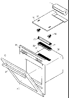
[0029] FIG. 1 is an exploded perspective view of an upper
structure of a cavity of an electric oven according to an
embodiment of the present invention and FIG. 2 is a partial
perspective view of a halogen heater according to an embodiment
of the present invention.
[0030] Referring to FIGs. 1 and 2, an electric oven according
to an embodiment of the present invention includes a cavity 30
defining a cooking chamber, a light wave generating unit 20
mounted on an upper portion of the cavity 30, a partition plate
for covering the light wave generating unit 20, and a cooling
fan 11 placed on the partition plate 10 and cooling an electric
8
CA 02541915 2006-04-05
component room.
[0031] As a light source of the light wave generating unit, a
halogen heater may be employed. The light wave generating unit
20 generates heat and far infrared rays. That is, when the
electric oven employs the light wave generating unit 20, the food
is equally cooked at its inner and outer portions by the heat
containing the far infrared rays. That is, the light wave is
distributed equally through the food, thereby equally cooking the
food at the outer and core portions of the food. Furthermore,
the light wave energy generated from the heater is intensively
radiated to the food by a reflecting plate to improve the heating
efficiency. In addition, by the stereo-heating of the halogen
heater emitting the light wave, the temperature of the cavity
increases up to 300 C in five minutes. Therefore, the cooking
speed of the electric oven of the present invention is three
times the prior art electric oven. As the cooking speed
increases, the disruption of nutrients and the vaporization of
the moisture can be reduced, thereby effectively maintaining the
inherent tastes of the food.
(0032] A front portion of the cavity 30 is opened and closed
9
CA 02541915 2006-04-05
by a door 32. Mounted on a rear portion of the cavity 30 are a
convection heater and a convection fan. Sheath heaters (not
shown) are mounted on inner-upper and inner-lower portions of the
cavity 30.
[0033] A door handle 321 is formed on a front-upper portion
of the door 32. A transparent window 322 is provided on a
central portion of the door 32 so that a user can identify the
cooking state of the food. A control panel including a
manipulation knob and the like is provided on the front-upper
portion of the cavity 30.
[0034] Particularly, one the sheath heater is mounted on an
inner-top of the cavity 30 and the light wave generating unit 20
having the halogen heater is mounted on an outer-top of the
cavity. According to circumstance, only one of the sheath heater
and the light wave generating unit may be mounted. Preferably,
the light wave generating unit 20 is mounted on the outer-top of
the cavity 30.
[0035] The cavity 30 is provided at the top with a plurality
of through holes 31 through which the heat generated from the
light wave generating unit 20 is directed into the cavity 30.
CA 02541915 2006-04-05
The portion where the through holes 31 are formed is coated with
enamel.
[0036] The light wave generating unit 20 includes a halogen
heater 22, a heater cover 23 enclosing the halogen heater 22, a
connector 21 connecting the halogen heater 22 to an electric wire
26, a supporter 24 for supporting the connector 21, a base 25
supporting the heater cover 23, the supporter 24 and the like,
and a heat discharge unit 100 enclosing the connector 21. The
heat discharge unit 100 fitted in guide holes 120 formed on the
partition plate 10.
[0037] The halogen heater 22 is a light source generating
visual and infrared rays and enables the high power as compared
to its size. The halogen heater 22 may be formed in a variety of
shapes as occasion demands.
[0038] The heater cover 23 serves to receive the halogen
heater 22 and shield the top surface of the base. The heater
cover 23 is screw-coupled to a top surface of the base 25. The
heater cover 23 may be formed of stainless steel that is heat-
resistant and corrosion resistant. The heater cover 23 extends
in a longitudinal direction to receive the halogen heater 22.
11
CA 02541915 2006-04-05
[0039] A protruding step 251 having a predetermined width is
formed on an edge of the base 25. The protruding step 251 allows
the cavity 30 to be further spaced away from the halogen heater
22 so that the through holes 31 can be protected from the heat
emitted from the halogen heater 22. Moreover, the protruding
step 251 serves to attenuate the heat transfer from the cavity to
the connector 21.
[0040] Meanwhile, the halogen heater 22 penetrates opposite
ends of the heater cover 23. That is, opposite ends of the
halogen heater 22 are exposed to both sides of the heater cover
23. The connector 21 is mounted on the exposed opposite ends of
the halogen heater 22. That is, the halogen heater 22 is
connected to an end of the connector 21 and the electric wire 26
is connected to the other end of the connector 21 to apply an
electric current to the halogen heater 22. The connector 21 is
supported by the supporter 24.
[0041] The connector 21 includes a glass body (not shown) and
a metal layer (not shown) formed on the glass body. Therefore,
when the temperature of the connector 21 increases to a
predetermined level, a gap may be created between the metal layer
12
CA 02541915 2006-04-05
and the glass body due to a thermal expansion difference between
the metal layer and the glass body. When air is introduced
through the gap, the service life of the filament of the halogen
heater 22 is quickly reduced.
[0042] Therefore, in order to increase the service life of
the light wave generating unit 20, the temperature of the
connector must be maintained at a predetermined level less than
250 C. Therefore, in the present invention, the connector 21 is
designed to be cooled by disposing the heat discharge unit 100
around the connector 21 and exposing the upper portion of the
heat discharge unit 100 to the cooling passage of the electric
component room 12. The exposing portion of the heat discharge
unit 100 to the cooling passage of the electric component room 12
is provided with a plurality of heat discharge fins. The heat
discharge unit 100 will now be described in more detail.
[0043] FIG. 3 is a partially broken perspective view of an
upper portion of the cavity of the electric oven according to an
embodiment of the present invention and FIG. 4 is an enlarged
view of the upper portion of the heat discharge unit according to
an embodiment of the present invention.
13
CA 02541915 2006-04-05
[0044] Referring to FIGs. 3 and 4, the heat discharge unit
100 of the present invention includes a main body 101, a
connector receiving portion 102 depressed on a bottom of the main
body 101 to receive the connector 21, and a plurality of heat
discharge fins 110 attached on the outer circumference of the
main body 101.
[0045] The outer circumference of the connector 21 tightly
contacts the inner circumference of the connector receiving
portion 102 so that the heat generated from the connector 21 can
be effectively transferred to the electric component room 12. An
upper portion of the main body 101 is partly exposed to the
cooling passage of the electric component room 12. The heat
discharge fins 110 are fixed on the exposed portion of the main
body 101 to the electric component room.
[0046] The heat discharge unit 100 may be formed of aluminum
having high heat conductivity. In order to improve the cooling
performance of the heat discharge unit 100, the heat discharge
unit 100 and the connector 21 contacts each other as close as
possible. At this point, it is preferable that the heat
discharge unit 100 does not contact the cavity 30.
14
CA 02541915 2006-04-05
[0047] The heat discharge unit 100 is divided into upper and
lower portions by the partition plate 10. That is, the connector
receiving portion 102 is formed on the lower portion of the heat
discharge unit 100 with reference to the partition plate 10 and
the heat discharge fins 110 are formed on the upper portion of
the heat discharge unit 100.
[0048] The light wave generating unit 20 is received between
the partition plate 10 and the cavity 30 and an insulation member
105 is inserted between the partition plate 10 and the cavity 30
except for the portion where the light wave generating unit 20.
As described with reference to FIG. 1, the partition plate 10 is
provided with the guide holes 120. The upper portion of the heat
discharge unit 100 is inserted in the guide holes 120 and exposed
to the electric component room 12. That is, the heat discharge
fins 110 fixed on the outer circumference of the main body 101
are exposed to the cooling passage of the electric component room
12. A rear end of the partition plate 10 is slightly curved
downward so as to provide a space for receiving the cooling fan
11. The air generated by the cooling fan 11 flows along the
cooling passage formed above the partition plate 10. The cooling
CA 02541915 2006-04-05
passage will be described more in detail later.
[0049] Meanwhile, the insulation member 105 is closely
coupled to the heat discharge unit 100 to intercept the heat
transferred from the cavity 30 to the connector 21. That is, the
insulation member 105 prevents the heat loss in the cavity 30.
[0050] In order to allow the heat exchange between the heat
discharge fins 110 and the air flowing along the cooling passage
to be effectively realized, the heat discharge fins 110 are
formed on right and left surfaces of the heat discharge unit 100
and extend in a direction in parallel to a direction where the
air flows along the cooling passage. A length of each heat
discharge fin 110 may be longer than that of the heat discharge
unit 100 so that the heat exchange can be quickly realized. The
heat discharge fins 110 may be further formed on front and rear
surfaces of the heat discharge unit 100. The number, length and
forming location of the heat discharge fins 110 may vary
according to a target cooling performance and a product where it
is applied. The heat discharge fins 110 are preferably formed of
aluminum having high thermal conductivity. As far as the cooling
performance can be improved, the heat discharge fins 110 can by
16
CA 02541915 2006-04-05
mounted on any locations of the upper portion of the heat
discharge unit 100.
[0051] The heat discharge unit 100 is structured to be
coupled to the heater cover, the supporter 24 and the like
without forming additional holes. Since no hole is formed on the
light wave generating unit 20 or the top surface of the cavity 30,
the heat loss in the cavity can be prevented.
[0052] FIG. 5 is a sectional view taken along line I-I' of
FIG. 3 and FIG. 6 is a sectional view taken along line II-II' of
FIG. 3.
[0053] Referring to FIGs. 5 and 6, the heat generated from
the connector 21 of the light wave generating unit 20 of the
present invention is transferred to the heat discharge unit 100.
[0054] That is, the heat generated from the connector 21 is
transferred to the inner circumference of the connector receiving
portion 102 of the heat discharge unit 100 and is further
transferred to the upper portion of the main body 101. The heat
transferred to the upper portion of the main body 101 is
transferred to the heat discharge fins 110. The heat transferred
to the heat discharge fins 110 are absorbed by the air flowing
17
CA 02541915 2006-04-05
along the cooling passage. Therefore, the temperature of the air
flowing along the cooling passage increases as the air passes
through the heat discharge unit 100, while the temperature of the
connector 21 decreases. In addition, since the outer
circumference of the connector 21 closely contacts the inner
circumference of the connector receiving portion 102, the heat is
transferred to the contact portion. At this point, the heat
conductivity may vary according to the number and size of the
heat discharge fins 110 formed on the outer circumference of the
heat discharge unit 100.
[0055] FIG. 7 is a sectional view of a coupling structure of
the heat discharge unit according to another embodiment of the
present invention.
[0056] In an embodiment of FIG. 7, the connector receiving
portion 102 of the heat discharge unit 100 may be formed by
cutting away a portion of a lower end of the heat discharge unit
100. However, in this embodiment, the connector receiving
portion 102 is formed by forming a circular hole 102a having a
diameter identical to an outer diameter of the connector 21 on
the heat discharge unit 100.
18
CA 02541915 2006-04-05
[0057] That is, the circular hole 102a is formed at a
location elevated from a lower end of the heat discharge unit 100
and the connector 21 is inserted in the circular hole 102a. In
this case, since the contacting surface between the connector 21
and the circular holes 102a, the heat exchange area between the
connector 21 and the heat discharge unit 100 increases, thereby
quickly cooling the connector 21. Moreover, the heat generated
from the connector 21 is not transferred to the cavity 30 or the
base 25 but directly transferred to the heat discharge unit 100.
Therefore, a phenomenon where the base 25 or the supporter 24 is
heated by the heat generated from the connector 21 can be
prevented.
[0058] In order to prevent the heat transferred to the heat
discharge unit 100 from being further transferred to the base 25
or the cavity 30, a bottom surface of the heat discharge unit 100
is spaced apart from a top surface of the supporter 24 by a
predetermined distance T.
[0059] FIG. 8 is a side sectional view of a cooling structure
of the heat discharge unit of the electric oven according to
another embodiment of the present invention.
19
CA 02541915 2006-04-05
[0060] Referring to FIG. 8, the electric oven is provided at
an outer side of the cavity 30 with the cooling passage. That is,
a cabinet 34 is disposed around the cavity 30 and the cooling
passage is defined between the cavity 30 and the cabinet 34.
[0061] The cooling fan 11 is disposed at a portion of the
cooling passage to suck the room air. That is, the door 32 is
provided at a lower portion with a room air intake hole.
Therefore, when the cooling fan 11 operates, the room air is
sucked through the room air intake hole. The room air sucked by
the cooling fan 11 is discharged from a rear side of the electric
component room to a front side of the electric component room 12.
The door 32 is provided at an upper portion with a room air
discharge hole. Therefore, the air flowing along the cooling
passage is discharged through the room air discharge hole. The
air passing through the cooling passage of the electric component
cools a variety of electric components in the electric component
room 12 as well as the exposed portion of the heat discharge unit.
[0062] It will be apparent to those skilled in the art that
various modifications and variations can be made in the present
invention. Thus, it is intended that the present invention covers
CA 02541915 2006-04-05
the modifications and variations of this invention provided they
come within the scope of the appended claims and their
equivalents.
21