Note : Les descriptions sont présentées dans la langue officielle dans laquelle elles ont été soumises.
CA 02541955 2006-04-04
PRINTING UNIT OF A WEB-FED ROTARY PRESS
BACKGROUND OF THE INVENTION
1. Field of the Invention
The invention relates to a printing unit of a web-fed rotary press having a
plurality
of press units and at least one impression cylinder, each press unit having a
printing
cylinder and a transfer cylinder for printing single color images on a web.
2. Description of the Related Art
Printing units of web-fed rotary presses, in particular of newspaper presses,
have
a plurality of press units, each press unit comprising a transfer cylinder, a
forme cylinder
and an inking unit, and optionally a damping unit. The forme cylinders are
also called
plate cylinders and the transfer cylinders are also called blanket cylinders.
Furthermore
printing units of this type can have impression cylinders, it being possible
for one
impression cylinder to interact with one or more transfer cylinders of
different press
units. The transfer cylinders are also called satellite cylinders. In addition
to printing
units which have impression cylinders of this type, printing units are also
known which
do not have impression cylinders, the transfer cylinders of two press units
rolling on one
another in printing units of this type without impression cylinders.
Accordingly, a web-fed
rotary printing unit having a plurality of press units comprises a plurality
of forme
cylinders and a plurality of transfer cylinders and optionally one or more
impression
cylinders. The present invention relates to printing units which have a
plurality of forme
1
CA 02541955 2006-04-04
cylinders, a plurality of transfer cylinders and at least one impression
cylinder. Printing
units of this type are also called satellite printing units. Satellite
printing units of web-fed
rotary presses usually have four press units and accordingly four forme
cylinders and
four transfer cylinders and one or two impression cylinders. Satellite
printing units of this
type having four press units and one impression cylinder are called nine-
cylinder
printing units; printing units having four press units and two impression
cylinders are
called ten-cylinder printing units, in contrast.
In a satellite printing unit of this type, single-color printed images for
preferably a
plurality of printed pages are applied in the region of each press unit in one
printing
color onto the printing material which is moved through between the transfer
cylinders
and the or each impression cylinder. For this purpose, in what is known as a
thrown-on
position of the printing unit, a pressure has to be applied firstly between
the forme
cylinders and the transfer cylinders of the press units and secondly between
the transfer
cylinders and the respective impression cylinders, this pressure being
provided by
pivoting in or throwing on the transfer cylinders to the respective forme
cylinder and to
the respective impression cylinder. For this purpose, the transfer cylinders
are usually
mounted eccentrically and positioned relative to the respective forme cylinder
and
impression cylinder in such a way that a center point of the transfer
cylinders does not
lie on a connecting line between center points of the corresponding forme
cylinders and
impression cylinders. Rather, a connecting line of a center point of a
transfer cylinder
with the center point of the corresponding impression cylinder encloses an
angle
between 5° and 40° with the connecting line of the center points
of the corresponding
2
CA 02541955 2006-04-04
forme cylinders and impression cylinders. Here, however, the transfer
cylinders and
forme cylinders are arranged symmetrically with respect to one another, with
regard to a
vertically extending axis.
The transfer cylinders, the forme cylinders and the or each impression
cylinder of
printing units of this type are subjected to deflection on account of their
inherent weight
and on account of the pressure or contact forces. This deflection depends, in
particular,
on the design of the cylinders, relatively thin cylinders being subjected to a
relatively
pronounced deflection. As a result of the deflection of the transfer cylinders
and forme
cylinders and impression cylinders, a considerable deviation in the
circumferential
register can be produced between the single-color printed images which are to
be
printed in the different press units of the printing unit, which deviation
impairs the print
quality. As has already been mentioned, these deviations in the
circumferential register
are particularly pronounced when relatively thin cylinders are present.
In relatively thin cylinders, the ratio of printed pages which are positioned
next to
one another axially to printed pages which are positioned behind one another
in the
circumferential direction is great, as, for example, in 6/2 cylinders in which
six printed
pages are positioned next to one another in the axial direction and in each
case two
printed pages are positioned behind one another in the circumferential
direction. The
same is true for 3/1 cylinders and 4/1 cylinders.
3
CA 02541955 2006-04-04
SUMMARY OF THE INVENTION
Proceeding from this, the present invention is based on the problem of
providing
a novel printing unit of a web-fed rotary press having minimized deviations in
the
circumferential register.
According to the invention, the forme cylinders and/or the transfer cylinders
are
positioned asymmetrically. The deflection of the cylinders can be influenced
with the
asymmetrical arrangement of the forme cylinders and/or transfer cylinders of
the
printing unit, in order thus to minimize deviations in the circumferential
register. As a
result, the print quality can be increased considerably.
The forme cylinders and/or the transfer cylinders are preferably positioned
asymmetrically with respect to a vertically extending axis, this axis
extending through
the rotational axis of the impression cylinder in a printing unit having one
impression
cylinder. In contrast, in a printing unit having two impression cylinders, the
impression
cylinders are positioned symmetrically with respect to this axis.
The forme cylinders and/or the transfer cylinders are positioned
asymmetrically in
such a way that, in the region of all the press units, horizontal lines during
the transfer of
the or each printing forme onto the printing material are curved uniformly
and, in relation
to the transport direction of the printing material, in the same direction.
Accordingly, in the region of all the press units, the transfer cylinders are
positioned downstream of and behind or upstream and in front of a connecting
line
which extends through the center points of the forme cylinder and impression
cylinder of
the respective press unit, in relation to the transport direction of the
printing material.
4
CA 02541955 2006-04-04
Preferred developments of the invention result from the following description.
Without being restricted thereto, exemplary embodiments of the invention will
be
explained in greater detail using the drawing.
Other objects and features of the present invention will become apparent from
the
following detailed description considered in conjunction with the accompanying
drawings. It is to be understood, however, that the drawings are designed
solely for
purposes of illustration and not as a definition of the limits of the
invention, for which
reference should be made to the appended claims. It should be further
understood that
the drawings are not necessarily drawn to scale and that, unless otherwise
indicated,
they are merely intended to conceptually illustrate the structures and
procedures
described herein.
BRIEF DESCRIPTION OF THE DRAWINGS
Fig. 1 is a schematic end view of a printing unit of a web-fed rotary press
according to the prior art;
Fig. 2 is a plot showing a deviation in the circumferential direction which is
produced in the press unit of Fig. 1;
Fig. 3 is a schematic end view of a printing unit of a web-fed rotary press,
according to a first exemplary embodiment of the invention; and
Fig. 4 is a schematic end view of a printing unit of a web-fed rotary press,
according to a second exemplary embodiment of the invention.
5
CA 02541955 2006-04-04
DETAILED DESCRIPTION OF THE PRESENTLY PREFERRED EMBODIMENTS
Before the invention is described in greater detail in the following text with
reference to Figs 3 and 4, a printing unit which is known from the prior art
of a web-fed
rotary press, namely a newspaper press, will be described with reference to
Figs 1 and
2.
Fig. 1 shows a printing unit 10, known from the prior art, of a web-fed rotary
press, the printing unit 10 including four press units 11, 12, 13 and 14 and,
accordingly,
four forme cylinders 15, 16, 17 and 18, and four transfer cylinders 19, 20, 21
and 22. In
addition to the forme cylinders 15 to 18 and transfer cylinders 19 to 22, the
press units
11 to 14 have inking units (not shown) and optionally damping units. In the
printing unit
10 of Fig. 1, each forme cylinder 15 to 18 of each press unit 11 to 14 rolls
on the
respective transfer cylinder 19 to 22 of the corresponding press unit 11 to
14, all of the
transfer cylinders 19 to 22 of all of the press units 11 to 14 rolling on a
common
impression cylinder 23. Accordingly, the printing unit of Fig. 1 is configured
as what is
known as a nine-cylinder printing unit.
In the printing unit 10, a web-shaped printing material 24 is printed in the
region
of each press unit 11 to 14 with single-color printed images in one printing
color, the
printing material 24 being moved through between the transfer cylinders 19 to
22 and
the impression cylinder 23 for this purpose, according to Fig. 1. Here, first
single-color
printed images are applied in the region of the printing unit 11 to the
printing material
24, and further single-color printed images are printed one after another in
the press
units 12, 13 and 14 onto the printing material 24, it being necessary, in
particular, to
6
CA 02541955 2006-04-04
minimize displacements in the circumferential register between the single-
color printed
images in order to achieve as high a print quality as possible, in order that
the single-
color printed images are printed onto the printing material 24 with exact
congruence.
In the printing unit 10 of Fig. 1, the transfer cylinders 19 to 22 and the
forme
cylinders 15 to 18 are positioned symmetrically with respect to a vertically
extending
axis A-A which extends through a rotational axis or a center point of the
impression
cylinder 23 in the case of the nine-cylinder printing unit. As the forme
cylinders 15 to 18,
the transfer cylinders 19 to 22 and the impression cylinder 23 are subjected
to a
deflection as a consequence of their inherent weight and the contact forces
which act
on them during printing, a straight, horizontal line on the form cylinders 15
to 18 is
shown curved on the printing material 24. Accordingly, in the printing unit 10
of Fig. 1,
the deviations in the circumferential register which are shown in Fig. 2
result between
the single-color printed images which are to be printed in the press units 11
to 14. In
Fig. 2, the axial extent of the cylinders or the width of the printing-
material web is plotted
on the horizontal axis and the curvature of the lines which are transferred by
the forme
cylinders 15 to 18 relative to the transport direction of the printing
material 24 is plotted
on the vertical axis. The curve 25 corresponds to the curvature of a line
which is printed
onto the printing material 24 in the press unit 11 by the forme cylinder 15
and via the
transfer cylinder 19. The curve 26 corresponds to the curvature of the line
which is
printed in the press unit 12 by the form cylinder 16 and via the transfer
cylinder 20. In
the same way, a straight, horizontal line on the forme cylinder 17 in the
press unit 13
becomes the arched curve 27 during the transfer of ink via the transfer
cylinder 21, and
7
CA 02541955 2006-04-04
a straight, horizontal line on the forme cylinder 18 in the press unit 14
becomes the
arched curve 28 on the printing material 24 during the transfer of ink via the
transfer
cylinder 22. The vertical spacing between the curves 25 to 28 corresponds to
the
deviation in the circumferential register at the respective axial position of
the printing
material between the single-color printed images which are to be printed in
the press
units 11 to 14. Here, in particular, the deviations in the circumferential
register between
the press units which are passed through by the printing material 24 in a
different
transport direction are particularly large. It can thus be gathered from Fig.
1 that the
transport direction of the printing material 24 changes between the press
units 12 and
13, for which reason the deviations in the circumferential register between
the press
units 11 and 13, 11 and 14, 12 and 13 and 12 and 14 are greater than the
deviations in
the circumferential register between the press units 11 and 12 and 13 and 14.
In order to minimize deviations in the circumferential register, it is
proposed
within the context of the present invention to position or arrange the forme
cylinders
and/or the transfer cylinders of a printing unit asymmetrically.
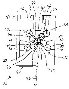
Fig. 3 therefore shows a first exemplary embodiment of a printing unit 29
according to the invention of a web-fed rotary press which is configured as a
nine-
cylinder printing unit, that is to say which comprises four press units 30 to
33 and,
accordingly, four forme cylinders 34 to 37 and four transfer cylinders 38 to
41 and one
impression cylinder 42. The transfer cylinders 38 to 41 of all the press units
30 to 33
role on the common impression cylinder 42, a web-shaped printing material 43
being
moved through befirveen the transfer cylinders 38 and 41 and the impression
cylinder
8
CA 02541955 2006-04-04
42, in order to print a single-color printed image onto the printing material
43 in the
region of each press unit 30 to 33. The forme cylinders 34 to 37 of the
respective press
unit roll on the transfer cylinders 38 to 41 of each press unit 30 to 33.
In the exemplary embodiment of Fig. 3, the forme cylinders 34 to 37 are
arranged
symmetrically with respect to a vertically extending axis A-A which extends
through a
rotational axis or a center point 44 of the impression cylinder 42. In
contrast, the transfer
cylinders 38 to 41 are positioned asymmetrically relative to this vertical
axis A-A. Here,
the transfer cylinders 38 to 41 are arranged asymmetrically with respect to
one another,
in such a way that, for all the press units 30 to 33, the sum of the
tangential
displacements between the forme cylinders 34 to 37 and the associated transfer
cylinders 38 to 41, and between the transfer cylinders 38 to 41 and the
impression
cylinder 42, are curved uniformly and, in relation to the transport direction
of the printing
material 43, in the same direction. In the exemplary embodiment of Fig. 3,
rolling
regions 45 of the transfer cylinders 38 to 41 lie on the impression cylinder
44 in the
region of all the press units 30 to 33, in relation to the transport direction
of the printing
material 43, downstream of and behind a connecting line of the respective
press unit 30
to 33, which connecting line extends through center points 46 of the forme
cylinders 34
to 37 and through the center point 44 of the impression cylinder 42. Fig. 3
shows these
connecting lines between the center point 44 of the impression cylinder 42 and
the
center points 46 of the forme cylinders 34 to 37 of the press units, with
dashed lines.
The rolling regions 45 of the transfer cylinders 38 to 41 of each press unit
and the
9
CA 02541955 2006-04-04
impression cylinder 42 lie downstream of or behind these connecting lines, in
relation to
the transport direction of the printing material 43.
As has already been mentioned, in the exemplary embodiment of Fig. 3, the
rolling regions between the transfer cylinders and the impression cylinder are
positioned
in the region of each press unit downstream of the connecting lines between
the forme
cylinder and impression cylinder, in relation to the transport direction of
the printing
material. As an alternative to this, it is also possible to position the
transfer cylinders
asymmetrically in such a way that these rolling regions lie upstream or in
front of the
connecting lines between the forme cylinders and the impression cylinder, in
relation to
the transport direction.
In the exemplary embodiment of Fig. 3, the printing unit is configured as a
nine-
cylinder printing unit. In the context of the present invention, it is also
possible to
configure the printing unit as a ten-cylinder printing unit, two impression
cylinders then
being present in this case. In this case, in each case two transfer cylinders
of two press
units then roll on both impression cylinders, the impression cylinders being
positioned
symmetrically with respect to the vertical axis A-A. Deviations in the
circumferential
register can also be minimized in a ten-cylinder printing unit of this type by
a
correspondingly asymmetric positioning of the forme cylinders and/or transfer
cylinders.
Fig. 4 shows a further exemplary embodiment of the printing unit 47 according
to
the invention, the printing unit 47 also being configured as a nine-cylinder
printing unit,
in the same way as the printing unit 29 of Fig. 3. In order to avoid
unnecessary
repetitions, identical reference numerals are used for identical assemblies
and only
CA 02541955 2006-04-04
those details are discussed in the following text, by way of which the
exemplary
embodiment of Fig. 4 differs from the exemplary embodiment of Fig. 3.
In the exemplary embodiment of Fig. 4, both the forme cylinders 34 to 37 and
the
transfer cylinders 38 to 41 are positioned asymmetrically, namely
asymmetrically with
respect to the vertically extending axis A-A which extends through the center
point 44 of
the impression cylinder 42 in the nine-cylinder printing unit. Here, the
transfer cylinders
38 to 41 and the forme cylinders 34 to 37 are again arranged or positioned
asymmetrically in such a way that, for all the printing units 30 to 33, the
sum of the
tangential displacements between the forme cylinders 34 to 37 and the
associated
transfer cylinders 38 to 41, and between the transfer cylinders 38 to 41 and
the
impression cylinder 42, is curved uniformly and, in relation to the transport
direction of
the printing material 43, in the same direction, that is to say, therefore,
rolling regions of
the transfer cylinders 38 to 41 lie in the region of all the press units 30 to
33 on the
impression cylinder 42 either downstream of and behind or upstream and in
front of a
connecting line between the forme cylinders 34 to 37 and the impression
cylinder 42.
Although not shown in the figures, it is also possible to position only the
forme
cylinders of the press units asymmetrically with respect to the vertically
extending line
A-A, and in contrast to arrange the transfer cylinders symmetrically with
respect to this
vertically extending axis A-A. Within the context of the invention, it is also
possible in
this way to minimize deviations in the circumferential register between single-
color
printed images which are to be printed onto the printing material in the press
units.
11
CA 02541955 2006-04-04
Thus, while there have shown and described and pointed out fundamental novel
features of the invention as applied to a preferred embodiment thereof, it
will be
understood that various omissions and substitutions and changes in the form
and
details of the devices illustrated, and in their operation, may be made by
those skilled in
the art without departing from the spirit of the invention. For example, it is
expressly
intended that all combinations of those elements and/or method steps which
perform
substantially the same function in substantially the same way to achieve the
same
results are within the scope of the invention. Moreover, it should be
recognized that
structures and/or elements and/or method steps shown and/or described in
connection
with any disclosed form or embodiment of the invention may be incorporated in
any
other disclosed or described or suggested form or embodiment as a general
matter of
design choice. It is the intention, therefore, to be limited only as indicated
by the scope
of the claims appended hereto.
12