Note : Les descriptions sont présentées dans la langue officielle dans laquelle elles ont été soumises.
CA 02542169 2006-04-06
METHOD AND APPARATUS FOR FABRICATING HIGH
FIN-DENSITY HEATSINKS
FIELD OF THE INVENTION
This invention relates in general to the manufacture of heatsinks, and
more specifically to a method for coupling fins in a high fin-density heatsink
to
dual heat-dissipating base plates.
BACKGROUND OF THE INVENTION
Heatsinks are known in the art for receiving and then dissipating heat
generated by electronic circuits in modern devices. Such well known
heatsinks typically comprise one base unit to which the heat generating
electronic devices are mounted, and a plurality of fins projecting from the
base
unit for dissipating the generated heat. It is a challenge to maximize the
surface area of the fins in order to provide optimum heat transfer from the
heat sink to the surrounding atmosphere while ensuring good thermal contact
between the base unit and the fins.
Heatsinks fabricated by metal extrusion have been proposed, wherein
the fins and the base units are of integral construction and thereby have the
optimum thermal contact. However, as discussed in the disclosure of U.S.
Patent No. 5,406,698 (Lipinksi), it has been shown that there are limits to
the
size and shape of fins that may be made by way of extrusion manufacturing.
There has thus been proposed various methods of manufacturing whereby
the fins are extruded separately from the base unit, and subsequently coupled
using various methods.
USP 5,771,966 (Jacoby) discloses a folded heat conducting member or
fin with at least one annealed metal insert having a predetermined thickness
corresponding to a distance between the first and second heat conductive
portions of the fin and a predetermined thickness corresponding to a depth of
the groove in the base plate so that the annealed metal insert conforms to the
shape of the groove when deformed to secure the base portion engaging
CA 02542169 2006-04-06
2
region of the folded heat conducting member into the-groove. The Jacoby
patent proposes an impacting die to perform a deforming or swaging function
to deform the fin while in the groove so that it is not removable.
United States Patent No. 6,263,956 to Tang et al. sets forth a heat
dissipating structure and method of manufacture where each slot in the base
has a width slightly less than a thickness of an inserting portion of the
associated heat dissipating fin, so that it will allow the heat dissipating
fin to
tightly insert therein. A fixing frame is then moulded into place for securing
the fins. The fixing frame is formed by introducing a melt fixing material
inside
of fixing recesses and thereafter cooling. As the material forms a solid, it
forms the fixing frame that secures the heat dissipating fins onto the base.
Published U.S. Patent Application No. 2002/0007936 (Vlloerner et al.)
discloses one or more folded-fin assemblies "tacked" to the base at selected
points by laser welds. In a subsequent operation, the full surface of the
lower
web portions of the folded-fin assemblies are bonded to the base, typically by
brazing. According to the Woerner disclosure, some suitable mechanical
means is used to urge the lower web portions against the base prior to the
laser welding, to optimize the contact between the lower web portions and the
base when the subsequent brazing takes place. Also, a finger tool is used to
maintain the desired spacing between adjacent fins prior to laser welding, to
optimize that spacing and avoid the possibility of adjacent fins being
positioned unevenly or in contact with each other. The heatsink assembly is
said to be unloaded from the laser welding apparatus and taken for brazing,
soldering or other suitable bonding to the base. As an example, the heatsink
assembly may receive a spray application of flux which is then oven-dried and
may be passed to a brazing furnace for heating to a temperature range of
1100-1120 °F to carry out the brazing.
Published U.S. Patent Application No. 2002/0043359 ~Mizutani) sets
forth a method of manufacturing a heatsink wherein fins are pressed by
means of a mould so that protrusions provided on the back side of the metal
plate are pressed into "bottom-expanded recesses" to fix the heat dissipation
fins and the base plate together. Mizutani teaches an impact-die mold for
CA 02542169 2006-04-06
3
pressing protrusions in the base plate against the fins to keep them secure to
the base plate.
Mentioned above, U.S. Patent No. 5,406,698 (Lipinksi), proposes a
heat sink manufactured by providing a baseplate with several parallel grooves
in its surface. Individual fins are manufactured having a dovetail or bell-
bottom
at their end, the ends then being inserted into respective grooves. The base
plate is subsequently deformed in the areas between the parallel channels by
rolling a plurality of coaxial rollers through the areas in order to crimp or
swage the fins into the grooves. The Lipinski apparatus is an excellent design
that requires little pressure to be transmitted though the fins themselves, so
that their tendency to undesirably buckle under downward pressure is
minimised. However, in the process of deforming the base unit in the areas
between the parallel channels, the entire base unit tends to warp. To this
end,
U.S. Patent No. 5;638,715 (Lipinski) sets forth an apparatus for subsequently
reversing the warp effect.
With increased consumer demand for more complex electronic
systems; the need has arisen for the more efficient use of space when
manufacturing these systems. To help meet this demand, dual base plate
heatsinks have been proposed that are mounted to more than one electronic
device but that dissipate heat through a common set of fins. With these
proposals have come a corresponding set of challenges for manufacturing the
heatsinks to specifications that promote excellent heat transfer and good
contact between the base plates and the fins. For example, the Lipinksi
apparatus would not be sufficient for the manufacture of dual baseplate
heatsinks because the proposed roller assembly would not be permitted to
pass through the spaces between the fins once the second base plate was in
place.
SUMMARY OF THE INVENTION
According to the present invention, a high fin-density dual base plate
heatsink is manufactured by placing fins side by side in channels formed in
each of two opposing base plates. In order to couple the base plates and the
fins, the relative distance between the base plates is held constant and a
CA 02542169 2006-04-06
4
swaging tool is passed both adjacent the fins and between the base plates in
a direction parallel to the base plates. The pressure exerted by the swaging
tool against the base plates adjacent the fins as the base plates are held at
a
constant relative distance swages the base plate adjacent each fin against the
fin. Pressure is thus applied to the end of each fin inserted in each channel
thereby securing the fin to the base plate.
BRIEF DESCRIPTION OF THE DRAWINGS
A detailed description of the preferred embodiment is set forth in detail
below, with reference to the following drawings, in which:
Figure 9 is a perspective view of a completed heatsink made according
to the preferred method of the present invention;
Figure 2 is a perspective view of fins being mounted into a single base
plate, prior to the swaging operation according to the preferred method of the
present invention;
Figure 3 is a partial front view of a heatsink with a swaging tool being
passed adjacent its fins and against the base plates according to the
preferred
method of the present invention;
Figure 4 is a partial front view of a heatsink with the swaging tool
having passed further adjacent the fins thereby having caused swaging of the
base plates against each of the fins according to the preferred method of the
present invention;
Figure 5 is a cutaway partial side view of a shorter end of a tine of the
swaging too! being passed adjacent a fin prior to swaging the base plates,
according to the preferred method of the present invention;
CA 02542169 2006-04-06
Figure 6 is a cutaway partial side view of a taller end of a tine of the
swaging tool being passed adjacent a fin and against the base plates to
swage the base plates against the fin, according to the preferred method of
the present invention; and
Figure 7 is a cutaway perspective view of the apparatus for
manufacturing high-density heatsinks in accordance with the preferred
method of the present invention.
DETAILED DESCRIPTION OF THE PREFERRED EMBODIMENT
According to the present invention in its most general aspect, a dual
base plate heatsink is manufactured by providing two opposing. base plates,
each with an inward facing surface and a number: of elongate landing areas
separated by elongate channels. Fins are placed into the channels of the
opposing base plates and, while the base plates are being maintained at a
constant relative distance, a swaging tool is passed in a direction parallel
to
the surface adjacent the fins and between the base plates. As the tool is
passed it increasingly applies pressure to the landing areas of the base plate
adjacent the fins to swage the base plate material against the fins. The
swaging of the base plate causes pressure to be applied to the fins to force
them to remain coupled to the base plates:
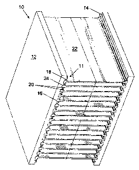
With reference to Figure 1, there is shown a dual base plate heatsink
made according to the preferred method of the present invention. The
heatsink 10 comprises two opposing base plates 12, each base plate having
an inward-facing surface 14. Landing areas 11 of base plate 12 are separated
by channels 16 and comprise an elongate jaw pair 18, having jaws 20. Fins 22
have flared ends 24 that frt in between adjacent jaw pairs 18 of respective
base plates 12. The channels 16 in the surface 14 between the jaw pairs 18
receive the flared ends 24 of the fins 22. As can be seen from the diagram,
the fins 22 are held in place by jaws 20 which have been swaged towards the
fins 22 to apply pressure to the flared ends 24 of the fins 22. The advantage
of
the flared ends 24 of the fins 22 is that when the jaws 20 have been swaged,
a more uniform and secure fit is achieved for increased heat transfer.
CA 02542169 2006-04-06
6
With reference to Figure 2, there is shown a heatsink 10 being made
according to the method of the present invention, wherein a fin 22 is being
lowered into one of the channels 16 between landing areas 11 of a base plate
12. Once all of the fins 22 have been placed into corresponding channels 16
between said jaw pairs 18, the second base plate 12 is fit onto the flared
ends
24 of the fins 22.
With reference to Figure 3, there is shown a front view of the heatsink
being made according to the principles of the present invention. In this
diagram, the fins 22 have been placed into corresponding channels 16
between landing areas 11 of the base plates 12, and a swaging tool 40 (fully
illustrated in Figure 7) has been placed through the fins 22 and into the
space
between jaws 20 in each jaw pair 18. This diagram shows clearly the flared
ends 24 of the fins 22 in between jaw pairs 18.
Furthermore, the shape of each jaw 20 is shown clearly. The jaws 20
progressively widen in cross section from the end distal to the surface 14 of
the base plate 12 towards the surface 14, and then narrow again. The base
plates are maintained at a constant relative distance, as discussed in greater
detail below with reference to Figure 7. The widening of the jaws 20 co-
operates with the wedge shape of the swaging tool 40 to progressively force
the jaws 20 apart when the tines 42 of the swaging tool 40 are being passed
between the respective jaws 20 in the jaw pairs 18. Furthermore, the
narrowing ensures that swaging the jaws 20 causes minimal warping of the
base plates 12 because of a lower bending moment.
In Figure 4, the tines 42 of the swaging tool 40 are caused to slide in a
direction parallel to the surfaces 14 of base plates 12 and between the jaws
20. Because the tines 42 of the swaging tool 40, shown more clearly in
Figures 5 - 7, are increased in height towards its second end, they push
against the jaws 20 of the landing area 11 to swage them apart and against
the flared ends 24 of the fins 22. Because the base plates 12 are being
maintained at a constant relative distance, the jaws 20 are forced apart due
to
the increase in pressure from the tines 42 as the swaging tool 40 is pulled
through the fins 22. The flared ends 24 of the fins 22 are pressed into
channels 16 of each base plate 12 and, because the jaws 20 of base plates
12 have been deformed, are retained therein.
CA 02542169 2006-04-06
7
Figures 5 and 6 show a side cutaway view of a single tine 42 of the
swaging tool 40 being passed between the base plates 12. As can be seek
the widened second end of the tine 42 pushes against both jaw pairs 18 of the
landing areas 11 on both base plates 12 to progressively force open the jaws
20 and push them against the flared ends 24 of the fin 22.
Figure 7 shows an exemplary view of the apparatus used to form the
heatsink 10 according to the present invention. The uncoupled heatsink 10 is
placed in a retaining structure having expansion-preventing walls 50 to
maintain the base plates 12 at a constant relative distance. The swaging tool
40 is shown having multiple tines 42 that are each pulled past the fins 22 of
the heatsink 10 to force open the jaws 20 in each jaw pair 18 of the landing
area 11 so that the jaws 20 push against the flared ends 24 of the fins 22 to
hold them in place in the channel 16 of the base plate 12.
In the embodiment of Figure 7, the tines 42 are pulled by a shaft 54
passing through a hole in each tine. The shaft is, in turn, pulled by a
hydraulic
motor or other motive apparatus. An alternate shaft attachment hole 56 is
shown in each of the tines 42.
Also shown in Figure 7 are slide-preventing walls 52 which act to
prevent the fins 22 from sliding relative to the base plates 12 when the tines
42 of said swaging tool 40 are pulled from left to right. The slide-preventing
walls avoid the requirement set forth in U.S. Patent No. 5,406,698 to, after
coupling of the fins 22 to the base plates 12, remove the parts of the fins 22
that have slid relative to the base plates 12 during application of swaging
pressure.
A person understanding the present invention may conceive of
alternatives and variations thereof. For instance, rather than employing slide-
preventing walls for preventing the fins from sliding relative to the base
plates,
a pressure force can be applied to both base plates to increase the friction
force between the fins and the base plates thereby reducing or prevent any
relative movement. Furthermore, whereas the flared fin ends of the preferred
embodiment provide a more uniform fit for better heat transfer with the jaw
pairs when swaged, uniform thickness fins can also be used.
CA 02542169 2006-04-06
An alternative to the smooth-sided fin shape, whether flared or not, is to
provide serrations on the end of the fin to improve bonding when the base
plate material is deformed against the fin.
All such embodiments and variations are believed to be within the
purpose, sphere and scope of the invention as defined by the claims
appended hereto.