Note : Les descriptions sont présentées dans la langue officielle dans laquelle elles ont été soumises.
CA 02542316 2006-04-10
WO 2005/036473 PCT/US2004/032867
UNIVERSAL KEY SECURITY METHOD AND SYSTEM
TECHNICAL FIELD
[0001] The present invention relates generally to a method and apparatus for
providing security, and more specifically to a method and apparatus for
providing key
secured access to a device such as a gaming machine.
BACKGROUND
[0002] In response to modern technological advances and varying needs to
protect property, combat crime, and prevent unwanted or unauthorized
intrusions,
increasingly sophisticated loclcs and locking devices are now common in many
homes
and businesses, such as banlcs, department stores, jewelry stores, shopping
malls,
schools, casinos and other gaming establishments. Such locks and locking
devices
can prevent unwanted access to a wide variety of areas and devices, especially
when
used in conjunction with additional security measures. While secured access
may be
desired with respect to persons or things physically entering a given
location, such as
a building or room, secured access may also may also be desirable with respect
to
accessing the contents of various devices such as, for example, safes,
lockboxes,
lockers, display cabinets, file cabinets, electronic or computer equipment,
and an
assortment of different secured devices. In some instances, such a secured
device
may have numerous secured regions with varied levels of security and
corresponding
requirements for accessing each region. One example of such a multi-level
secured
device could be a gaming machine (i.e., slot machine).
[0003] Because casinos and other forms of gaming comprise a growing multi-
billion dollar industry wherein large sums of money can quiclcly change hands
during
many types of fast paced games, casinos and other gaming establishments are a
prime
target for cheating and stealing, and thus a prime candidate for more
iiuiovative and
complex security devices and systems, wluch can include newer loclcs and
locking
devices. Because casinos and other gaming establishments in particular
frequently
utilize sophisticated security devices a.nd techniques, casinos and gaming
machines in
general comprise an ideal illustrative example for the types of locking
devices, and in
particular the universal lcey security methods and systems, disclosed herein.
CA 02542316 2006-04-10
WO 2005/036473 PCT/US2004/032867
Accordingly, the following discussion and illustrative examples are directed
primarily
to casino and gaming machine security devices and systems as a matter of
convenience, although it should be borne in mind that such security systems
and
devices are readily applicable to other types of establishments, venues and
items.
[0004] There are a variety of devices associated with a gaming machine that
can
require varying levels of security. Examples of devices for which security
measures
can be separate and independent include bill acceptors, coin drops or hoppers,
a game
EEPROM or Ceiztral Processing Uiit ("CPU"), and communication boards, among
others. Many Sllch devices are built into the gaming machine, although it is
possible
for one or more to exist outside of the machine itself. Traditionally,
security has been
provided with respect to a main door of a gaming machine by means of an
ordinary
mechanical hcey and lock apparatus. Additional internal devices within a
gaming
machine, such as those listed above, are also frequently secured with an
identical or
similar ordinary mechanical key and lock apparatus. Apparatuses and methods
for
providing keyed access to an area or device, such as for gaming machines
within a
casino, are generalhy well known, and insta~.ices of such apparatuses and
methods can
be found in, for example, U.S. Patent Nos. 4,677,834; 6,125,673 and 6,604,394,
ahh of
which are incorporated herein by reference in their entirety and for all
purposes.
[0005] It has also become popular of late for many gaming establishments to
add
an additionah access feature whereby lceyed access to a gaming machine or
gaming
machine component is preferably accompanied by use of an identifying card,
such as
an employee tracleing card. Such a card is read upon access to the machine,
such that
employee information and other transactional details can be noted and/or
tracked
locally or remotely. Use of such a card is mostly an informational tool,
however,
such that access to a gaming machine and any of its internal compartments can
still be
had so long as the person seelcing access has the appropriate mechanical hcey
or keys.
Use of such a card is also disadvantageous in that it introduces an additional
step into
the secured access process, which can be cumbersome and inconvenient.
[0006] Regardless of whether a card is used, unauthorized access to a gaming
machine may be possible for an experienced thief in some cases. Such access
can
also be rather easy where a key or set of keys falls into the wrong hands.
While key
theft, use of a lost lcey or unauthorized hcey duplication are some examples
of lceys
falling into the wrong hands, other instances include occasions where casino
personnel having some level of security access are terminated or otherwise
leave their
CA 02542316 2006-04-10
WO 2005/036473 PCT/US2004/032867
position and do not return their keys, as is typically required. Although
costly, it is
not unheard of for entire banlcs or floors of gaming machines to be refitted
with new
locks where a particular set of lceys is lost or stolen, or where a group of
machines has
been targeted repeatedly by those having improper access to one or more keys.
[0007] Accordingly, there exists a need for improved methods and systems for
providing secured access to an area or device via mechanical keys and locks,
and in
particular for such methods and systems to eliminate the need for a tracking
card
while providing better ways of ensuring against unauthorized access to a
gaming
machine, despite the presence of a correct mechanical lcey for that machine.
SUMMARY
[0008] It is an advantage of the present invention to provide a method and
apparatus for universal lcey security such that a higher level of security can
be had
with respect to a secured environment or object. According to one embodiment
of the
present invention, the provided method and apparatus involve the use of one or
more
specially desig~ied loclcs and/or keys in a gaming machine, whereby
unauthorized
access to the gaming machine is curtailed despite the presence of a correct
leey for
that particular machine. This is accomplished by designing the lock such that
one or
more additional criteria in addition to a physical lcey are needed in order to
open the
loclc. Such additional criteria can include the use of biometric information
or a PIN
number for an authorized user, or other factors beyond the shape of a
designated key.
[0009] In one particular embodiment, a mechanical key is utilized in
conjunction
with an electromechanical loclc, wherein the loclc requires both insertion and
operation of the mechanical lcey and a separate authorizing electrical signal
in order
to open. This separate electrical signal can be the result of a correct
reading of a
biometric parameter for an authorized user, such as a fingerprint. In one
instance, the
fingerprint of an authorized user can be read and approved by a device built
into the
mechanical lcey itself, whereupon a positive authorizing signal can be sent to
the
electromechanical lock to permit access. Alternatively, the fingerprint can
merely be
sensed by such a device within the lcey, with the data being sent to an
approval
mechanism either inside the gaming machine itself or at some remote location,
whereupon a positive authorizing signal can be relayed to the loclc if the
user of the
lcey is an authorized individual.
CA 02542316 2006-04-10
WO 2005/036473 PCT/US2004/032867
[0010] According to another embodiment of the present invention, the provided
method and apparatus involve the use of one or more alternative personal
identifiers
in addition to a mechanical lcey. Such personal identifiers can include a
numerical
keypad requiring the use of a Personal Identification Number or PIN, wherein
the
numerical lceypad can be on or near the device or item to be accessed, or on
the key
itself. W this mamzer, a mechanical key can be designed to contain one or more
indicia that reflect upon the particular loclc to be opened, such as the
particular key
shape and profile for correctly manipulating the mechanical pins or levers
within the
lock, as well as one or more indicia that reflect upon the particular
authorized user,
such as a fingerprint.
[0011] Other methods, features and advantages of the invention will be or will
become apparent to one with skill in the art upon examination of the following
figures
and detailed description. It is intended that all such additional methods,
features and
advantages be included within this description, be within the scope of the
invention,
and be protected by the accompanying claims.
BRIEF DESCRIPTION OF THE DRAWINGS
[0012] The included drawings are for illustrative purposes and serve only to
provide examples of possible structures and process steps for the disclosed
inventive
universal lcey security method and apparatus. These drawings in no way limit
any
changes in form and detail that may be made to the invention by one skilled in
the art
without departing from the spirit and scope of the invention.
FIG. 1 illustrates in perspective view an exemplary gaming machine
according to one embodiment of the present invention.
FIG. 2 illustrates in perspective view the gaming machine of FIG. 1 having an
opened main door according to one embodiment of the present invention.
FIG. 3 illustrates in side perspective view an exemplary electromechanical
loclc according to one embodiment of the present invention.
FIG. 4 illustrates in side elevation view an exemplary mechanical lcey having
an embedded biometric device according to one embodiment of the present
invention.
FIG. 5 illustrates in magnified side elevation view the electrical contacts of
the mechancal lcey of FIG. 4 according to one embodiment of the present
invention.
FIG. 6 illustrates in side perspective view an alternative exemplary
electromechanical loclc according to one embodiment of the present invention.
CA 02542316 2006-04-10
WO 2005/036473 PCT/US2004/032867
FIG. 7 illustrates in side elevation view an alternative exemplary mechanical
key having an embedded biometric device according to one embodiment of the
present invention.
FIG. 8 illustrates a block diagram of a particular "non-system controlled"
universal key security reading system according to one embodiment of the
present
invention.
FIG. 9 illustrates a bloclc diagram of an alternative "system controlled"
universal lcey security reading system according to another embodiment of the
present
invention.
FIG. 10 illustrates a block diagram of a particular network infrastructure for
providing a universal lcey security method and system according to one
embodiment
of the present invention.
FIG. 11 illustrates an exemplary database containing associated data
identifiers of various authorized and canceled individuals according to one
embodiment of the present invention.
FIG. 12 illustrates a flowchart of one method of providing a universal key
security method and system according to one embodiment of the present
invention.
DETAILED DESCRIPTION
[0013] An example application of a method and system according to the present
invention is described in this section. This example is being provided solely
to add
context and aid in the understanding of the invention. It will thus be
apparent to one
skilled in the art that the present invention may be practiced without some or
all of
these specific details. In other instances, well known process steps have not
been
described in detail in order to avoid unnecessarily obscuring the present
invention.
Other applications are possible, such that the following example should not be
talcen
as definitive or limiting either in scope or setting.
[0014] W the following detailed description, references are made to the
accompanying drawings, which form a part of the description and in which are
shown, by way of illustration, specific embodiments of the present invention.
Although these embodiments are described in sufficient detail to enable one
skilled in
the art to practice the invention, it is understood that these examples are
not limiting;
such that other embodiments may be used, and changes may be made without
departing from the spirit and scope of the invention.
CA 02542316 2006-04-10
WO 2005/036473 PCT/US2004/032867
[0015] One advantage of the present invention is the provision of a method and
apparatus for universal lcey security such that a higher level of security can
be had
with respect to a secured environment or object. In one embodiment, one or
more
specially designed locks and/or keys are provided, whereby unauthorized access
to an
area or device is curtailed despite the presence of a correct lcey for that
particular area
or device. This is accomplished by designing a lock such that one or more
additional
criteria in addition to a physical key are needed in order to open the lock.
Such
additional criteria can include the use of biometric information or a PIN
number for
an authorized user, or other factors beyond the shape of a designated key.
[0016] As discussed previously, while the inventive universal key security
method and system disclosed herein is being described primarily with
references to
and illustrations of gaming establishments and gaming maclunes, this system is
readily adaptable for use in other types of businesses and environments, such
that its
use is not restricted exclusively to gaining machines or within a gaming
establislnnent. Continuing now with the illustrative example of a universal
key
security method and system within a casino or other gaming establishment, it
is
common knowledge that such establishments are prime targets for thieves,
cheats and
other assorted criminal actors both on the outside and "inside." In
particular, slot
machines and other gaming machines are a favored mark for many types of
attempted
thefts and cheats for a variety of reasons. Thus, gaming machines are
particularly
pertinent devices for illustrating the functions and capabilities of the
inventive
method and system disclosed herein.
[0017] Turning now to FIG. l, an exemplary gaming machine according to one
embodiment of the present invention is illustrated in perspective view. Gaming
machine 10 includes a top box 11 and a main cabinet 12, which generally
surrounds
the machine interior (not shown) and is viewable by users. Main cabinet 12
includes
a main door 20 on the fiont of the machine, which opens to provide access to
the
interior of the machine. Attached to the main door are typically one or more
player-
111p11t switches or buttons 21, one or more money or credit acceptors, such as
a coin
acceptor 22, and a bill or ticlcet validator 23, a coin tray 24, and a belly
glass 25.
Viewable tluough main door 20 is a primary video display monitor 26 and one or
more information panels 27. The primary video display monitor 26 will
typically be
a cathode ray tube, high resolution flat-panel LCD, plasmalLED display or
other
conventional electronically controlled video monitor. Top box 11, which
typically
CA 02542316 2006-04-10
WO 2005/036473 PCT/US2004/032867
rests atop of the main cabinet 12, may also contain a ticket printer 28, a
lcey pad 29,
one or more additional displays 30, a card reader 31, one or more speakers 32,
one or
more cameras 33, and a secondary video display monitor 34, which may also be a
cathode ray tube, high resolution flat-panel LCD, plasma/LED display or other
conventional electronically controlled video monitor. Other components and
combinations are also possible, as is the ability of the top box to contain
one or more
traditionally reserved for main cabinet locations, and vice versa.
[0018] Gaming machine 10 also includes one or more locking devices designed to
restrict access into the gaming machine. Such devices can comprise mechanical
or
electromechanical locks requiring the use of one or more lceys, with
preferably at
least one loclc being key accessible at some location on the outside of the
machine.
Such locks can include, for example, warded, bit, barrel, cylinder, pin
tumbler, wafer
tumbler, wafer side bar, tubular, vending and utility style locks, as well as
any other
style loclc, as desired. Similarly, such keys can include, for example, bit,
barrel, flat,
tubular, cylinder and tubular style lceys, as well as any other style key, as
desired. As
illustrated in FIG. 1, a main door lock comprises at least one key access on
the
outside surface of the machine, such as, for example, key access 41, through
which a
lcey can be used to unloclc and open main door 20. In addition, one or more
internal
machine components may be directly accessible from the outside of the machine,
with one example being of such access being external belly door 50, which
comprises
a lock also having a lcey access 51 on the outside surface of the machine.
Although
not shown, additional machine components may also be directly accessible from
the
outside of the machine in a similar manner. Alternatively, one or more
internal
machine components may require more than one level of access, with one example
being the need to unloclc and open main door 20 before unlocking and accessing
an
internal machine component.
[0019] With reference to FIG. 2, the gaming machine of FIG. 1 having an opened
main door is illustrated in perspective view. In additional to the exterior
items
described above, such as top box 1 l, main cabinet 12 and primary video
display
monitor 26, gaming machine 10 also comprises a variety of internal components.
Such components include, for example, a coin acceptor 35, main door locking
mechanisms 42 and 43, the reverse side of belly door 50, and a number of other
items
not listed here as a matter of convenience. Main door locking mechanisms 42
and 43
comprise a standard hooked bar and receptacle slot mechanical locking system,
CA 02542316 2006-04-10
WO 2005/036473 PCT/US2004/032867
wherein hoolced bar 42 is actuated up and down to lock or unloclc main door 20
through a successful operation of lcey access 41. Although this particular
mechanical
loclcing system has been introduced for purposes of illustration, it will be
understood
that any other standard locking system is interchangeable with that which is
illustrated, as other such loclcing systems will also suffice to achieve the
objects and
purposes of the inventive universal key security methods disclosed herein.
[0020] As seen in FIG. 2, a number of additional secured areas having loclcs
with
key accesses for same are also included within the internal regions of gaming
machine 10. For example, internal bill acceptor 60 comprises a loclced bill
storage
area having lcey access 61. Similarly, a secured electronics region 70
comprises a
locked box for holding the machine CPU and/or other critical electronic
components,
with the lock having lcey access 71. Other internal components not shown, such
as a
coin drop, coin hopper or electronic communications board, for example, can
also be
similarly secured. In this manner, not only must one open the main door 20 of
the
gaming machine, but one must also overcome additional security means or
measures
to access one or more of these internal regions, with each internal region
preferably
having different access requirements than the main door and every other
internal
region respectively. Alternatively, as stated above, one or more internal
components
may be directly accessible without the need for opening main door 20. One such
example involves the access of internal bill acceptor 60, which can be
accomplished
through the opening of external belly door 50 via key access S 1 and internal
bill
acceptor 60 via key access 61 while the main door remains closed.
[0021] Turning now to FIG. 3, an exemplary electromechanical lock according to
one embodiment of the present invention is illustrated in side perspective
view.
Electromechanical lock 40 comprises a cylinder style mechanical loclc having a
lcey
access 41, one or more associated locking mechanisms 42, an external housing
44 and
one or more electrical connections 45. As set forth above, favorable control
and
movement of locking mechanism 42 is accomplished as a result of a successful
operation of the loclc, preferably via key access 41 through use of an
authorized key
by an authorized user. In a preferred embodiment, lock 40 cannot be
successfully
operated without both the use of an appropriate mechanical lcey and the
inclusion of
an authorizing electrical signal in the loclc. This authorizing electrical
signal can be
sent into the lock .from an outside source via connection 45, or can be
generated
entirely from within the loclc, lcey access, and/or key itself. Alternatively,
any type of
CA 02542316 2006-04-10
WO 2005/036473 PCT/US2004/032867
wireless communications, such as a wireless fidelity ("Wi-Fi") type example of
a
Bluetooth'~ Wireless system utilizing an IEEE 802.1x or other similar standard
networking technology, can be utilized to transmit the authorizing signal. In
the
event that both a mechanical lcey and authorizing electrical signal are
present, one or
more solenoids or other actuating devices within the electromechanical lock
are then
activated such that locking mechanism 42 can be favorably manipulated.
[0022] Such a favorable condition of having both a correct key and an
authorizing
electrical signal may result in the ability of lcey access 41 being rotatable,
whereupon
rotation of the lcey within the lcey access will then control the loclcing
mechanism.
Alteunativehy, lock 40 can be designed such that an appropriate mechanical key
can
always be rotated within the lcey access, except that the appropriate solenoid
or other
actuating mechanism within the loclc will not actually be activated without an
appropriate authorizing electrical signal being present. Methods and
apparatuses for
using solenoids or other actuating mechanisms within an electromechanical
loclc are
well known in the art, and it is specifically contemplated that any such
appropriate
method or apparatus can be used in conjunction with the inventive universal
key
security methods and systems disclosed herein.
[0023] One example of an advanced electromechanical lock and system usable in
conjunction with gaming machines, and in particular with the present
invention, is
described in commonly assigned and co-pending U.S. Patent Application No.
09/824,621, by Mattice, et al. filed on April 2, 2001, and entitled "Method
and
Apparatus for Controlling Access to Areas of Gaming Machines," which
application
is incorporated herein in its entirety and for all purposes. Another exemplary
use of a
mechanical lcey and other information in conjunction with gaming machines and
systems is described in commonly assigned U.S. Patent No. 6,439,996, which
issued
to LeMay, et al. on August 27, 2002, and is entitled "Key for a Gaming Machine
and
Method of Use Thereof," which patent is also incorporated herein in its
entirety and
for all purposes. As discussed herein, use of the disclosed electromechanical
loclc and
system is preferably accomplished within a gaming machine or system through
the
use of user specific data or information, such as biometric information.
Another
example of biometric information being used in conjunction with gaming
machines
and systems is described in commonly assigned and co-pending U.S. Patent
Application No. 091491,899, by Wells, et al. filed on January 27, 2000, and
entitled
CA 02542316 2006-04-10
WO 2005/036473 PCT/US2004/032867
"Gaming Terminal and System with Biometric Identification," which application
is
also incorporated herein in its entirety and for all purposes.
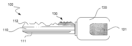
[0024] Referring now to FIG. 4, an exemplary mechanical lcey having an
embedded biometric device according to one embodiment of the present invention
is
illustrated in side elevation view. Mechanical lcey 100 comprises a cylinder
lcey
having a profiled component 110 and a handle 120. Profiled component 110 is
preferably constructed from a hard metal or plastic, such that its shape and
profile
will be substantially maintained over time. For purposes of discussion herein,
it will
be assmned that this component is made out of metal, and in particular steel,
although
a variety of other suitable materials are possible and are also contemplated.
This
metal region of the key includes one or more indicia that can be "read" by a
loclc to
determine whether or not the lcey is a correct key for that lock. Such indicia
can
include a number of characteristics such as a groove arrangement, a side
profile, one
or more edge profiles and/or the overall physical shape of the key.
[0025] Specific lcey shape 11 l, which is essentially a combination of the
side
profile and groove arrangement for the profiled component 110, is commonly
used in
many types of metal keys. This side profile and groove arrangement essentially
permit the lcey to be physically received into certain types of locks,
including the type
for which the lcey is intended, while blocking it from being received into
most other
types of loclcs. The side profile can include a variety of grooves formed
along the
side of profiled component 11 l, as well as any number of wholesale twists and
turns,
frequently between 3 and 7. Each groove and each profile twist or turn can
function
as a separate index for distinguishing lcey 100 from many other keys.
Accordingly,
specific shape or side profile 111 is one source of indicia comprising
information or
data specific to a lock whereby lcey 100 can be read. Profiled or metal
component
110 also includes at least one and sometimes two edge profiles 112, which are
used to
manipulate pins and/or levers within the loclc tumbler or other internal loclc
structure.
Each rise, fall, tooth, valley and plateau along an edge profile can function
as a
separate index for lcey 100, such that edge profile 112 is another source of
indicia
comprising information specific to a lock whereby lcey 100 can be read. If key
100 is
indeed the correct lcey for a given lock, then its specific shape 111 will
allow it to fit
the lock, while its edge profile 112 will push all the necessary pins and/or
levers
within the lock into their correct positions for access, such that the loclc
"reads" the
lcey as being coiTect, as will be readily understood by those skilled in the
art.
CA 02542316 2006-04-10
WO 2005/036473 PCT/US2004/032867
[0026] I~ey handle 120 can be constructed from the same material as the rest
of
the lcey, but is preferably made of a plastic, resin or other hardened and
electrically
insulating material. According to one embodiment of the present invention,
handle
120 includes at least one biometric device 121, which is preferably embedded
within
the handle, and is preferably a fingerprint sensor. Such a fingerprint sensor
can be an
MBF300 Fingerprint SweepsensorTM manufactured by Fujitsu, Ltd. of Tolcyo,
Japan,
or either of the EntrePad AES3400 or AES2500 Fingerprint Sensors manufactured
by
AuthenTec, lilc. of Melbourne, Florida, for example, although other brands and
types
of fingerprint sensors can be effectively utilized as well. This fingerprint
sensor is
preferably designed to sense one or more critical portions of a fingerprint,
such that a
decision can be made on whether or not a user of the key is an authorized
user.
Techniques for the electronic reading, analysis and determination of
fingerprints are
well laiown in the art, and any such technique is contemplated as being usable
in
conjunction with the present invention. Accordingly, a fingerprint or other
form of
biometric data is one source of indicia comprising information or data
specific to a
particular user of lcey 100.
[0027] A decision on whether a sensed fingerprint is indeed authorized can be
made in any number of ways, such as through a smart chip or other processor
within
the fingerprint sensor itself or embedded elsewhere on the lcey handle, or by
a remote
processor to which the fingerprint sensor communicates information regarding
the
fingerprint being sensed. Such a remote analysis and decision may be desirable
for a
number of reasons. For example, the expense involved in inserting a
microprocessor
into a key handle can be considerable, and may tend to result in a more
fragile key.
In addition, the ability of a cheat or thief to defraud a system may be
enhanced where
a lcey processed signal design permits the intercepting and/or mimicking of an
appropriate authorization signal emanating from the lcey itself. Conversely, a
design
that has only a fingerprint sensor on the key with the analysis and
authorization being
done remotely is lilcely to have more safeguards against tampering and fraud.
In any
event, one or more electrical signals are preferably sent and/or received from
key 100
as a way of communicating data and/or authorization status with respect to the
fingerprint sensed at the lcey handle, and such electrical signals can be
communicated
through an electrical contact region 130 of the lcey, a Wi-Fi type or other
wireless
system or other communication means, as desired. In addition, any communicated
11
CA 02542316 2006-04-10
WO 2005/036473 PCT/US2004/032867
data and/or authorization signal or status is preferably encrypted through any
of a
number of readily available encryption programs or systems.
[0028] Although the foregoing illustrative example has been made with respect
to
the biometric example of a fingerprint, it will be readily understood that
other forms
of biometric information can be used in place of or in conjunction with a
fingerprint.
Examples of such additional biometric features include facial features, for
which
facial recognition programs are available, vocal tones and features, for which
voice
recognition programs are available, and retinal features, for which retinal
scan
devices are available. Any one of these or a variety of other biometric
indicators can
be used in conjunction with the provided universal key security method and
system to
result in an application whereby some particular biometric feature of an
authorized
key user is stored and utilized to compare to a subsequently read biometric
feature of
an attempted lcey user to verify whether the attempted key user is legitimate.
[0029] Alternatively, a non-biometric informational source can be utilized to
provide indicia specific to one or more authorized key users. Such a non-
biometric
informational source can comprise, for example, a numerical, alphabetical
and/or
symbolic manual keypad adapted to accept a Personal Identification Number
("PIN")
or similar access code. In one embodiment, such a keypad can comprise an
ordinary
10-key numerical keypad, wherein the PIN for an individual can be any
numerical
code having a convenient series of numbers, preferably from four to ten digits
in
length, although both shorter and longer lengths of digits are also
contemplated.
Preferably, an authorized PIN is known only to a particular user or a
restricted group
of users, such that entry of an authorized PIN appropriately reflects indicia
that are
specific to one or more authorized lcey users. An operable keypad can be
miniaturized and built onto the mechanical lcey itself or, alternatively, can
be installed
at a location at or near the electromechanical loclc to be opened. Such a
location may
be on the object to be accessed, such as a gaming machine, or on some other
readily
accessible nearby device, wall or other structure. Readers for other indicia,
such as a
fingerprint sensor, voice detection system or retinal scanner can also be
similarly
located at or near the electromechanical lock to be opened.
[0030] Another item that can be used to provide specific indicia for use in
the
universal lcey security methods and systems disclosed herein is a Radio
Frequency
Identification ("RFID") tag. An RFID tag generally comprises a tiny integrated
circuit chip that is programmed to contain particular information, whereby
such
12
CA 02542316 2006-04-10
WO 2005/036473 PCT/US2004/032867
information can be transmitted upon the reception of an appropriate radio
frequency
("RF") signal. One or more antennae are typically attached to the RFID tag to
aid in
the reception and transmission of RF signals, and the overall size of a
typical RFID
tag can be on the order of a flalce of pepper. Use of RFID tags has been
compared to
the use of standard UPC bar codes and scanners, although most RFID tags can
store
an exponentially greater amount of information than a bar code, and do not
require
direct line of sight and other physical factors to be satisfied in order to be
activated
and read by a tag reading device emitting and receiving RF signals.
[0031] In the present invention, one or more RFID tags may be used in order to
provide a source of identifying indicia with respect to the mechanical key
being used.
Such identifying indicia are preferably in addition to one or more other
sources of
indicia as discussed above. hi such an RFID tag utilizing embodiment, an RFID
tag
can be programmed to have a set code, with such a tag to be preferably
embedded
within an associated mechanical lcey 100. An RFID tag reader can be located
within
or about a gaming machine of interest, such that the tag reader will emit an
RF signal
at least when a mechanical lcey is inserted into a lock of the gaming machine.
If the
RFID tag embedded within the mechanical key being used emits an appropriate
code
upon activation, and that code is then read by the tag reader, then an
authorizing
signal can be sent from the reader to the electromechanical lock. Preferably,
the lock
is designed such that it will not open unless and until it receives such an
authorizing
signal. Such an adaptation is useful in instances where, for example, an
individual
has attempted to create unauthorized copies of the mechanical lcey, which
copies
would presumably not work properly without an embedded RFID tag containing a
correctly programmed code.
[0032] Similarly, an electromechanical lock utilizing any associated biometric
or
non-biometric sources of user specific indicia will preferably likewise not
become
operable until an authorizing signal is sent to the lock from whatever device
or
devices are measuring and analyzing such user specific indicia to confirm the
presence of an authorized user. Such analyzing devices can be in the form of a
smart
chip or processor within the lcey itself, or can be in the form of separate
units within
the loclc or located remotely from the lock. Such separate units may take the
form of,
for example, numeric keypads with a built in microprocessor, an analytical
unit
within the electromechanical loclc itself, or a remote unit in communication
with the
lock. Such a remote unit can be part of a network, whereby a centralized
general
13
CA 02542316 2006-04-10
WO 2005/036473 PCT/US2004/032867
purpose server or specialized security server is utilized to regulate and
monitor a
variety of security items, including access to a number of gaming machines.
Further
discussion of such a system, as well as one means of implementing electrical
communications between a mechanical lcey and a corresponding lock and/or
system,
S is provided in greater detail below.
[0033] In this manner, a much higher level of control over locking systems and
their respective distributed mechanical keys may be had by a managing entity,
such as
a casino operator. Should one or more lceys become lost or stolen, such lceys
could
presumably not be used by just anyone, despite the ability of the lcey to fit
physically
into its designated lock or locks. Because an unauthorized user would
presumably
not be able to satisfy an inquiry associated with the lock as to whether the
user is an
authorized user, simple possession of a key will typically be insufficient to
grant
access to the secured environment of interest. Consequently, casino
establishments
and other business owners would not be required to refit many machines with
new
locks and issue new lceys whenever a problem has taken place with respect to
one or
more mechanical keys. The resulting time and money that will be saved in the
long
nm by not requiring such practices is thought to be substantial.
[0034] Tl1r11111g now to FIG. S, the electrical contact region 130 of the
mechanical
key of FIG. 4 is illustrated in magnified side elevation view. This region of
the
mechanical lcey is at least one example of a way to provide electrical
communication
between the lcey and an electromechanical lock and/or security network. As
detailed
above, profiled component 110 of the lcey preferably comprises a metal or
other hard
plastic material suitable for forming typical shapes, side profiles and edge
profiles in
mechanical keys. Insert 131 is preferably attached to the rest of the key
within a
recess or other designated area of profiled component 110 that abuts the
handle of the
key. Such an attachment can be accomplished via a press-fit design, glue,
welds,
epoxy or other suitable attachment means. Atop insert 131 are one or more
electrical
contacts 132-135, with such one or more contacts being used to transmit power
and/or
one or more electrical signals to and from the lcey. Due to the need for
multiple
electrical leads within a small space, insert 131 is preferably comprised of
an
electrically insulating material, such as plastic, resin, quartz, or glass,
for example,
with at least one internal electrical wire or lead (not shown) running from
each
electrical contact tluough the insert and to an electrical contact (not shown)
at the
edge of the handle abutting the insert.
14
CA 02542316 2006-04-10
WO 2005/036473 PCT/US2004/032867
[0035] Electrical contacts 132-135 are arranged such that each will make
contact
with a designated electrical contact within the tumbler or other internal
component of
the electromechanical lock when the lcey is fully inserted into the loclc.
Separate
leads or wires coluzected to each internal contact within the lock are then
connected to
one or more appropriate electronic distribution and/or analytical units
capable of
processing electrical signals sent from the lcey. While exactly four
electrical contacts
132-135 are illustrated in the present exemplary embodiment, it will be
readily
appreciated that a greater or fewer number of contacts arranged in any of a
variety of
formations and locations can also be utilized as desired. While USB type of
electrical
contacts are preferable, other standard or customized types of contacts are
also
contemplated. In this particular embodiment, contacts 132 and 133 can be
designated
for data transmission from (and also possibly into) the key, while contacts
134 and
135 are "power" contacts, whereby electrical power can be input into the key
to
operate the fingerprint sensor and microprocessor, if applicable.
Alternatively, the
lcey can contain a battery, whereby power is transmitted from the key to the
lock via
the power contacts on the lcey. In such an instance, it may be possible for
the lock to
have no power source other than that provided to it by the key.
[0036] In one embodiment, the mechanical key is not powered up until it
receives
power via power contacts 132 and 133 from a mechanical lock into which it is
inserted. At that time, an embedded fingerprint sensor reads the fingerprint
of the
person holding the handle of the lcey outside the lock, and either processes
and
analyzes this information itself, possibly through use of a smart chip or
processor also
located in the key handle, or sends fingerprint related data through data
contacts 134
and 135 to be processed by the lock or remotely. If fingerprint data is
processed and
analyzed locally within the lcey handle itself, then user data authentication
is said to
be "non-system controlled." In such cases, a control file having data
regarding a
correct fingerprint is preferably stored in one or more memory units within
the lcey
handle, such that the local smart chip or microprocessor in the lcey handle
can readily
access this control file on demand, compare data regarding the current
fingerprint on
the sensor, confirm whether a match has been made, and send an authorization
signal
to the lock via data contacts 134 and 135. Such an authorization signal can be
a
simple on or off signal, in which case only one data contact for sending an on
or off
signal 1111ght be needed, or can be somewhat encoded in pulses along one, two,
or
CA 02542316 2006-04-10
WO 2005/036473 PCT/US2004/032867
more data contacts in a manner that is readable by the lock, such that
attempts to
tamper or defraud the system are rendered substantially less likely to
succeed.
[0037] Alternatively, the lock may comprise its own power source while the
mechanical lcey may comprise an internal battery, such that power contacts are
not
needed. As another alternative, data contacts may also be eschewed in favor of
a key
and locking system that communicate entirely via RF signals. Such an
embodiment
could utilize a relatively complex RFID tag, or a smart chip or microprocessor
in
conjunction with an RF transceiver. Such an embodiment could include any type
of
Wi-Fi, Bluetooth° or other wireless communications, as discussed
previously. In the
instance of a mechanical lcey having an internal battery and utilizing RF
technology
for all data communications, electrical contacts may not be needed at all. In
the event
that analysis and authentication of a proffered fingerprint is not to be
accomplished
internally within the mechanical lcey itself, then user data authentication is
said to be
"system controlled." In such cases, one or more analysis or authentication
steps can
take place within or around the actual electromechanical lock, or at some
remote
location such as over a server-based networlc, as described in greater detail
below.
[0038] Referencing FIG. 6, an alternative exemplary electromechanical lock
according to one embodiment of the present invention is illustrated in side
perspective
view. Electromechanical loclc 40A is substantially similar to the
electromechanical
lock 40 of FIG. 3, except that lock 40A comprises a tubular style mechanical
lock
having a tubular lcey access 41A in addition to one or more associated locking
mechanisms 42, an external housing 44 and one or more electrical connections
45.
As in the foregoing example above, favorable control and movement of locking
mechanism 42 is accomplished as a result of a successful operation of the
lock,
preferably via key access 41A through use of an authorized key by an
authorized
user. Similarly, an authorizing electrical signal can be sent into the lock
from an
outside source via correction 45, or can be generated entirely from within the
lock,
key access, and/or lcey itself, with alternative types of wireless
communications such
as Bluetooth° and other Wi-Fi systems also being available for such
communications.
[0039] Referencing corresponding FIG. 7, an alternative exemplary mechanical
lcey having an embedded biometric device according to one embodiment of the
present invention is illustrated in side elevation view. Mechanical lcey 150
comprises
a tubular lcey having a profiled component 160 and a handle 170. As in the
foregoing
example, profiled component 160 is preferably constructed from a hard metal or
16
CA 02542316 2006-04-10
WO 2005/036473 PCT/US2004/032867
plastic, such that its shape and profile will be substantially maintained over
time.
This profiled component 160, which is typically cylindrical and hollow,
includes one
or more physical features such as individual cuts or grooves 161 and/or teeth
or
guides 162, the combination of which can be physically "read" by a lock to
determine
whether or not a particular tubular lcey is a correct key for that lock.
Similarly, key
handle 170 can be constructed from the same material as the rest of the key,
but is
preferably made of a plastic, resin or other hardened and electrically
insulating
material. According to one embodiment of the present invention, handle 170
includes
at least one biometric device 171, which is preferably embedded within the
handle,
and is preferably a fingerprint sensor, examples and functionality of which
are
provided above. As in the foregoing example, a fingerprint or other form of
biometric data is thus one source of indicia comprising information or data
specific to
a particular user of lcey 150.
[0040] Also similar to the foregoing example, one or more electrical signals
are
preferably sent and/or received from key 150 as a way of communicating data
and/or
authorization status with respect to the fingerprint sensed at the key handle.
Such
electrical signals can be communicated through an electrical contact region
180 of the
leey, a Wi-Fi type or other wireless system or other communication means, as
desired,
with any SLICK communicated data and/or authorization signal or status being
preferably encrypted through any of a number of readily available encryption
programs or systems. Electrical contact region 180 can be substantially
similar to the
electrical contact region 130 of the foregoing example, or can be modified as
desired
to fit the particular physical parameters of the various tubular lcey and lock
system
being used. Alternative locations for this region can be, for example, on or
nearer to
the lip or front end of the leey, or within the hollowed out region inside
profiled
component 160, if applicable. Although the -foregoing discussion and
illustrations
have been made with respect to cylinder and tubular keys and locks, it will be
readily
understood that other types of keys and loclcs can also be readily adapted for
use with
the inventive universal lcey security method and system disclosed herein, such
that
further examples would be cumulative and are not necessary.
[0041] Turning now to FIGS. 8-10, several block diagrams of particular
embodiments incorporating the universal lcey security method and system
according
the present invention are illustrated. As seen in FIG. 8, a non-system
controlled
universal lcey security reading system 200 comprises at least three basic
components,
17
CA 02542316 2006-04-10
WO 2005/036473 PCT/US2004/032867
an Input/output ("I/O") device 201, a power source 202 and at least one memory
unit
203. In this basic system, an I/O device can comprise, for example, a
fingerprint
reader, a voice recognition system, a retinal scanner, a numerical keypad, or
any other
suitable device for reading data associated with one or more particular users.
Such an
I/O device 201 will typically require power, which is provided via the power
source
202, which can comprise, for example, a battery embedded into the lcey handle,
aai
external battery or A/C power source delivered via one or more power contacts,
or in
some cases a sufficient level of RF energy emitted from a remote RF powering
and
reading device. I/O device 201 will also typically require access one or more
stored
control files in at least one memory unit 203 for comparison with specific
input on a
user whenever an access is attempted. Such a memory unit can comprise flash
memory, RAM, or any of a wide variety of memory types, but preferably
comprises
some form of ROM or other relatively stable memory device. As set forth
previously,
this non-system controlled embodiment operates to read indicia from a key user
and
analyze and authenticate such data entirely within the leey itself, such that
an
authentication signal is sent from the key itself to the lock upon the
confirmation of
proper user-related information.
[0042] As seen in FIG. 9, an alternative system controlled universal lcey
security
reading system 210 comprises not only an I/O device 211, a power source 212
and at
least one memory unit 213, but also at least three additional basic components
as
well. Central to this system controlled embodiment is the presence of a CPU
214, an
independently controlled sensor or other device within an electromechanical
lock
215, and a network 216. As detailed in the preceding system, I/O device 211
can
comprise, for example, a fingerprint reader, a voice recognition system, a
retinal
scanner, a numerical keypad, or any other suitable device for reading data
associated
with one or more particular users. While such an I/O device 211 may require
power,
such power can be delivered from a battery (not shown) located within the I/O
device
itself, or alternatively via an outside power source 212 either directly or
through
another component, such as the CPU 214. At least one memory unit 213 is also
present for comparison with specific input on a user whenever an access is
attempted,
although such a memory lllllt or units are typically to be accessed by the CPU
214, or
altelmatively by the network 216 in this system controlled embodiment. As in
the
above instance, memory unit 213 can comprise flash memory, RAM, or any of a
wide
18
CA 02542316 2006-04-10
WO 2005/036473 PCT/US2004/032867
variety of memory types, but preferably comprises some form of ROM or other
relatively stable memory device.
[0043] In the system controlled embodiment, data is sent from I/O device 211,
which can be, for example, a fingerprint sensor or numerical keypad, to the
CPU 214
and/or network 216 for evaluation and/or recordation. CPU 214, wluch can be
within
the electromechanical lock itself or elsewhere within the gaming machine, or
alternatively at some remote location receives data from I/O device 211 and
proceeds
to compare this offered data from a current user to one or more stored files
within one
or more memory units 213. Such a stored file can comprise, for example, a
plurality
of indices for a particular fingerprint of an authorized user. If a match
cannot be
confirmed, then no authorization signal is sent to the electromechanical lock,
such
that the lock is not opened. If a match is confirmed, then CPU 214 may be set
to
autonomously send an authorization signal to permit the lock to be opened, or
may be
required to confirm further information from the network 216 before doing so.
Such
fuuther information may comprise data relating to whether a given user is
still
cuiTently authorized within the network, or whether a given user has
restricted access
limited to certain machines or certain dates or times. Such further
information from
the networlc can be requested by the CPU either before, during or after it
receives and
analyzes data from the Il0 device, although the CPU will preferably not sent
an
authorization signal to the loclc until it obtains positive further
information from the
network permitting it to proceed. In addition to potentially assisting with
the
determination of the system on whether or not to permit the opening of the
lock,
networle 216 is also preferably utilized for the tasks of recording and
organizing
specific factual details regarding one or more users, machines and/or
transactions.
[0044] Assuming that a correct match of current user data is made with that
which is stored within one or more files, and that network approval has been
granted
if necessary, then CPU 214 sends an authorization signal to an independently
controlled sensor or other device within an electromechanical lock 215, such
that the
lock can then be opened, preferably so long as the mechanical key remains
inside the
lock to turn the lock physically as it opens. hl this manner, the electrically
controlled
stop on the entire lock must be satisfied through separate mechanisms either
inside
the secured enviromnent or remotely, malting it significantly harder to cheat
or
otherwise defraud the system merely because one has the mechanical key that is
adapted to physically fit within and operate the loclc.
19
CA 02542316 2006-04-10
WO 2005/036473 PCT/US2004/032867
[0045] FIG. 10 illustrates a bloclc diagram of a particular network
infrastructure
for providing a universal key security method and system according to one
embodiment of the present invention. Network 300, which may be substantially
similar to the networlc 216 discussed above, comprises a number of components
for
effectively administering the inventive universal lcey security methods and
systems
disclosed herein over a number of machines or even an entire establishment or
network of establishments. One or more gaming machines 10 in a plurality of
locations, either in banks or standing alone, or connected to the network via
any
desired operable connection means, such as by wiring to a common bus 301 that
can
be connected to at least one general-purpose server 310.
[0046] Such a general-purpose server 310 may be one that is already present
within an establishment for one or more other purposes in lieu of or in
addition to
security. Other functions for such a networked general-purpose server include,
for
example, accounting and payroll functions, Internet and e-mail capabilities,
switchboard communications, reservations and other hotel and restaurant
operations,
and other assorted general establishment operations. In some instances,
security
functions may also be associated with or performed by such a general-purpose
server.
For example, such a server may be linked to one or more gaming machines within
an
establislunent, and in some cases form a network that includes all or
substantially all
of the machines within that establishment. Communications can then be
exchanged
from each machine to one or more security related programs on the general-
purpose
server. For example, the server may be programmed to poll each machine for
affimnative security clearance on a regvilar basis to determine whether all is
well with
that machine. In addition, the server can be programmed to monitor each
potential
access within any of the gaming machines under its domain, such that any
successful
or unsuccessful attempt to access a gaming machine under the universal lcey
security
devices disclosed herein can be watched and/or recorded.
[0047] In a particularly preferred embodiment, however, networlc 300 also
comprises at least one additional special purpose or security server 320,
which is used
for various functions relating to security within the security networlc. Such
an
additional security server is desirable for a variety of reasons, such as to
lessen the
burden on the general-propose server or to isolate or wall off some or all
security
infomnation from the general-propose server and thereby limit the possible
modes of
access to such security information. In addition, security server 320 may be
used as
CA 02542316 2006-04-10
WO 2005/036473 PCT/US2004/032867
the exclusive controlling entity for any networlc needs with respect to any
universal
key security methods and systems being used by an establislunent.
Alternatively,
network 300 can be isolated from any other network within the establislnnent,
such
that a general purpose server 310 is entirely impractical, such that a special
purpose
S server 320 dedicated solely to universal leey security measures is
implemented.
Under either embodiment of an isolated or shared networlc, universal key
security
server 120 also preferably includes connections to a network 330 of one or
more
peripheral devices, as well as a database or other suitable storage medium
340.
Peripheral devices may include, but are not limited to, one or more video
monitors
331, one or more user terminals 332, one or more printers 333, and one or more
other
digital input devices 334, such as a card reader or other security identifier,
as desired.
[0048] Database 340 is preferably adapted to store many or all files related
to user
specific information, Sllch that these files might be accessed directly by a
requesting
machine CPU, or for backup purposes. Further information as to the status of
and
any pertinent restrictions with respect to each past or present authorized
user can also
be kept within this database. In addition, this database can also be adapted
to store
transactional related data for each time an access to a gaming machine is even
attempted. Parameters for storing such transactional related items can vary
widely,
and are left up to the discretion of the system administrators. Database 340
is also
preferably directly accessible by one or more of the peripheral devices on
network
330 connected to universal key security server 320, such that data specific to
given
users or transactions that are recorded on the database may be readily
retrieved and
reviewed at one or more of the peripheral devices. In addition, it is
contemplated that
one or more peripheral devices on network 330 may also be connected directly
to
common bus 301, as illustrated, although such an arrangement may not be
desirable,
depending on the level of security clearance desired within networlc 300.
[0049] Referring now to FIG. 11, an exemplary database containing associated
data identifiers of various authorized and canceled individuals according to
one
embodiment of the present invention is illustrated. As similarly illustrated
in FIG. 10,
database 340 is accessible to one or more servers, preferably at least
universal key
security server 320, and has a connection to a network 330 of one or more
peripheral
devices. Database 340 preferably contains information related to a plurality
of prior
machine access transactions, as well as information related to a plurality of
past and
present authorized users within the system. In addition, database 340 can be
21
CA 02542316 2006-04-10
WO 2005/036473 PCT/US2004/032867
constructed such that it also contains files with respect to other
individuals, such as
biometric data files on lmown or suspected cheats or thieves, such that a
possibly
fraudulent attempt to access a gaming machine might be more readily
attributable to a
known non-authorized individual rather than to nobody in particular.
[0050] Contained within database 340 are numerous files with respect to many
different past and present users of the system, and preferably all such users
are
contained within database 340 or a collection of associated databases. Such
files can
be classified according to presently authorized user files 341 and previous
but no
longer authorized user files 342. Contained within each file is a user profile
having
numerous informational items, restriction requirements, if any, access level
or levels,
and preferably at least one authentication file containing information for
that user that
is to be used to authenticate the user at the time that a mechanical lcey is
used. As
shown for user file 341A, such information can include items such as, for
example, an
employee name and number, a start date, a specific number for the mechanical
key or
keys issued to that employee, restriction information with respect to that
employee,
and one or more authentication types and files, among others. Restriction
information
can include the casinos, floors or locations to which that employee is
authorized, the
machine types, machine denominations, machine numbers, security types, levels
of
access within each machine, temporal restrictions with respect to time and
dates that
machines are accessible by that employee, and other such information. Such
information can not only be stored within a user file within the database, but
can also
be retrieved and utilized by the universal lcey security server 320 and/or a
CPU within
a gaming machine into which access is being attempted in order to determine
whether
an otherwise authenticated user is authorized for access at the particular
location,
machine, level within the machine, date and time that access is being
attempted.
[0051] As discussed previously, each secured lcey accessible environment, such
as a gaming machine, can have separate levels of security within the machine,
with a
separate authorization status required for each level for each system user.
For
example, a particular gaming machine may have different access levels for: I)
its
main door, II) its primary CPU, III) its bill acceptor, and IV) its coin drop.
Although
additional internal items can require access such that additional levels can
be added,
only the four listed levels will be discussed herein for purposes of brevity
and clarity.
Whether a user has access to one of these four levels is preferably
independent of
whether that same user has access to another, unless of course main door
access or a
22
CA 02542316 2006-04-10
WO 2005/036473 PCT/US2004/032867
similar broader level of access is required for an otherwise authorized access
to an
internal component requiring an open main door or access to the broader level.
[0052] In this example, the access levels for a particular user can be
designated as
I-II-III-IV, with a "1" or "Y" for yes and a "0" or "N" for no depending on
whether or
not a user is authorized for each given level. For instance, Sam the mechanic
is only
authorized to open the main door of the gaming machine, and nothing else.
Hence,
the user file 341 for Sam will contain an "Access Levels" designation of 1-0-0-
0.
Similarly, Joe the technician is permitted access to the main door and to the
CPU
region of the gaming machine, such that the Access Level designation for Joe
will
read 1-1-0-0. Continuing further, Bill the drop collector has an Access Level
designation of 1-0-1-1, while the designation for Ted the administrator is 1-1-
1-1. Of
course, more levels can be added and designated for each user, and the Access
Level
designations for each user can be altered over time, or set to 0-0-0-0 in some
cases.
[0053] W the event that an authorized user is demoted, discharged or otherwise
loses some or all of the access privileges previously granted to that user,
then such a
user file can be appropriately updated by a system administrator, or
alternatively
reclassified as a file for a user that is no longer authorized in any
capacity. In such
cases, user information and biometric files can be maintained within a
database in
order to possibly utilize such information in the future in the event that
unauthorized
access may be attempted at some point. In addition, it may be critical for
some
systems to rely on such input from the security server on the network, rather
than on
isolated and localized files within individual keys or machines, since status
updates as
to potential "de-authorizations" on such localized files would tend to be
nonexistent
or more sporadic than updates on the main network and server. While one
example
of a database for storing such valid user and burned or revolted user files
could be a
proprietary database designed for the specific association and use with the
inventive
lcey security method and system disclosed herein, other databases can be
utilized for
this purpose as well. Such other databases can include, for example, other
proprietary
databases associated with other functions within the casino or establishment,
private
databases from other entities that may or may not require subscriptions for
access and
use, and databases shared with various goverlrnent or reg~.ilatory agencies.
[0054] According to one embodiment of the present invention, a provided
apparatus or system, and preferably a network or like structure, is adapted to
record
data or information related to an attempted access of a gaming machine or
device as
23
CA 02542316 2006-04-10
WO 2005/036473 PCT/US2004/032867
the transaction occurs. Such live data capture can be used immediately in the
event
that an alarm needs to be triggered, and can also be stored indefinitely in
one or more
databases, such as the database described above. In the event that one or more
alarms
are to be triggered in conjunction with use of the present universal key
security
system, it is preferable that this system be at least somewhat intertwined
with one or
more elements of a greater security system and network within an establishment
or
casino, SLlch that any filmbling of keys, mis-punching of lceypad buttons,
improper
alignment or insufficient exposure of a finger or thumb with respect to a
fingerprint
sensor or any other common human error does not automatically trigger an alarm
and/or armed response.
[0055] Intertwined use with an existing security system can include the use
of, for
example, alarms and one or more security cameras and/or microphones, with such
cameras and microphones being possibly controlled from a control room or area,
whereby a first alarm merely signals an operator or automated computer
response to
focus at least one camera on the affected machine to monitor and/or record the
potentially problematic transaction. Live data capture can be used for other
purposes
as well, many of which involve the storing of such information for use at a
later time,
such as, for example, in the event of a power outage or other machine
shutdown, to
provide specific evidence corroborating the version of the casino operator as
to how a
certain transaction took place, or to track a pattern of use or misuse with
respect to
one or more machines or users.
[0056] Tl1r11111g now to FIG. 12, a flowchart outlining one method of
providing a
universal lcey security method and system according to one embodiment of the
present invention is illustrated. After a start step 370, a first step 372 of
receiving a
lcey into a lock initiates the process, upon which a subsequent step 374 of
providing
power to or otherwise enabling the mechanical key takes place. In the event
that
biometric or other data is provided at a location other than the mechanical
key itself,
then such other provision of user specific data is also "powered up" or
similarly
initiated at step 374. At a following step 376, the live data capture of
authentication
information and possibly other information related to a particular access
transaction
takes place. Live data that can be capW red in addition to any user specific
stored files
and present live authenticating information can include, for example, the
specific
machine and its location, the date and time of the access transaction, the
length of the
access, the different levels accessed within the machine, and the presence of
more
24
CA 02542316 2006-04-10
WO 2005/036473 PCT/US2004/032867
than one authorized individual at or near the machine, among others. Such live
data
capture is preferably accomplished through the transmission of data, with the
actual
transmission involving the encryption of data according to one or more
encryption
programs or systems.
[0057] Once a sufficient amount of live data has been collected from a key
user,
with such data being fingerprint data, other biometric data, or a PIN entry,
for
example, then the method proceeds to step 378, where the live data captured
can be
analyzed. This is accomplished by a CPU or other similar processor either
within the
lcey, the loclc, the gaming machine or remotely over a network. Once the
captured or
collected live data is analyzed, it is compared at a step 380 to data in a
control file
that is stored in one or more memory locations, as described in greater detail
above.
After such a comparison is made, an inquiry as to whether a match exists
between the
live captured data and the data on file is then made at a decision step 382.
In the
event that a match is indeed made, the process continues to a step 384,
wherein the
lock is opened and access to the machine or internal machine component is
permitted.
During or after this access, results and data are then forwarded to a
universal key
security server on the network at a subsequent step 386, whereupon the server
may
decide to discard some or all of the results and data, or store some or all of
it on an
associated database at a subsequent result logging step 388, whereupon the
method
reaches an end stage 394. Again, any transmission or communication of data,
results,
commands or other information is preferably accomplished through the use of
one or
more encryption programs or systems.
[0058] In the event that a match is not had in response to the inquiry made at
decision step 382, however, then the process continues to a step 390, wherein
physical access is denied to the overall gaming machine or internal component
of
interest contained therein. At a following step 392, an alarm sequence is then
initiated, whereby a full alarm and response can be sounded, or a notice
provided to
other security persomlel or systems that more attention is needed at the
concerned
gaming machine or device. After alarm sequence step 392, the process then
rejoins
the main process branch at informational forwarding step 386, where again the
network server may decide to discard some or all of the results and data, or
store
some or all of it on an associated database at a subsequent result logging
step 388,
whereupon the method reaches an end stage 394. As in the foregoing process
steps,
any transmission or cormnunication of data, results, commands or other
information
CA 02542316 2006-04-10
WO 2005/036473 PCT/US2004/032867
is preferably accomplished through the use of one or more encryption programs
or
systems.
[0059] Although the foregoing invention has been described in detail by way of
illustration and example for purposes of clarity and understanding, it will be
recognized that the above described invention may be embodied in numerous
other
specific variations and embodiments without departing from the spirit or
essential
characteristics of the invention. Certain changes and modifications may be
practiced,
and it is understood that the invention is not to be limited by the foregoing
details, but
rather is to be defined by the scope of the appended claims.
26