Note : Les descriptions sont présentées dans la langue officielle dans laquelle elles ont été soumises.
CA 02543560 2006-04-25
WO 2005/06181 I PCT/EP2004/053277
TRAI~'SLATION OF l'CT/EP2004/053277
WOOD WALL CONSTRUCTIOrI MADE OF WOODEN BEAMS
DIrSCRIPTION
The invention relates to a wood wall construction made of wooden beams,
wherein said
wooden beams are superposed and possibly juxtaposed and assembled with screws,
which are screwed into the mutual attachment area of two wooden beams in a
bridging
manner from the top or the bottom of the twe wooden beams and which extend
only over
a part of the height or the thickness of each v~~ooden beam.
When building such a wood wall construction made from wooden beams, the wooden
beams stacked on top of one another are connected to each other, with the
problem of
course being the fact that the screws do not ensure a positive durable
connection due to
the volume changes caused by shrinkage anc swelling. The publication of the
utility
patent DE 299 20 853 U 1, from which a wood wall construction of the type
mentioned at
the outset is known, provides for the elimination of the above-mentioned
problem in that
each screw is provided with a spring below the head, which is to create a
permanent
pressure by the thread of the screw being sc~ ewed-in and counter sunken and
thus
provides for an absolute firmness of the wal: made from beams. At least due to
this
spring, each screw hole must be pre-drilled ? or accepting said spring in this
known wood
wall construction.
Another imown embodiment (EP-0787866F 1 ) provides for machine screws to be
inserted
into pre-drilled holes adjusted to a stack of wooden beams each, with the
screws being in
a positive connection to one another by the read of the screws being provided
with
threaded holes, into which the end of the shaft of the subsequent screw,
provided with a
thread, can be screwed-in. In this manner, a type of a continuous fastening
rod is formed,
with the head of each individual screw beins supported at the upper side of a
wooden
beam respectively.
CA 02543560 2006-04-25
WO 2005/061811 PCTIEP2004/053277
From DE 198 28 275 A1 a wooden beam for luilding wooden houses is known. When
two such wooden beams are positioned on toF~ of one another and connected by
screws, a
hole is predrilled for each screw, which extezrds entirely through the upper
beam in the
form of a penetrating hole so that the thread c f the screw engages the lower
beam only.
A carrier made from wood is known from DF: 100 13 810 A1, having sections
subject to
lateral stress. Such sections particularly act i a the area of cut-outs or
penetrations of the
cattier. In order to compensate the lateral stress, rod-shaped elements are
provided which
are formed by screws, which are inserted, aml extend perpendicularly to the
longitudinal
direction of the carrier. These screws are screwed-in from the top or from the
bottom of
the carrier and each run over a part of the height of the carrier only and
thus they are
immediately allocated to the lateral tension of the loaded zone. This state of
prior art is
therefore relevant For a single wooden beam only, however not with regard to
its
connection to other wooden beams.
From the publication of the German utility patent DE 93 07 029 U1 it is known
to
connect exterior wall beams by way of cross-nailing.
The present invention is to attain the objecti~fe of providing a wood wall
construction
with the use of screws, which can be produced fast and simple and in which an
optimum
asse~rnbly of the wooden beams stacked on t~~p of one another can occur.
According to the invention this is achieved in that the wooden beams are
connected to
one another by screws provided with thread~:d sections at least at their two
end sections,
which are screwed-in without pre-drilling and which extend only over a pan of
the height
or the thickness of the wooden beam and th~xefore only engage the immediate
attachment
area of the two wooden beams, with the len;th of the screws being provided
shorter than
the height of the wooden beam.
According to the invention, the screws engs.ge only the immediate attachment
areas of the
two wooden beams and are screwed-in witb.out pre-drilling. Much shorter screws
are
CA 02543560 2006-04-25
WO 2005/061811 PCT/EP2004/0532?7
necessary only, which can also be counter sunken particularly deep. Due to the
considerably shorter screws to be inserted a p 3.rcicular saving in maternal
and expenses
can be achieved. Additionally, by the eonsid~rably shorter shaft having a
thread, the
screwing-in torque can be considerably reduced in reference to a long screw.
Due to the
considerably shorter dimensions of the screw > inserted according to the
invention a much
faster and shorter assembly time is achieved us well. The production of a wood
wall
construction is therefore considerably easier ~uZd faster by the measures
according to the
invention. In particular, it is ensured in this manner that the connection
maintains its
effectiveness even during the changes in volt~Tne occurring due to shrinkage
and swelling
of the wood parts to be attached. The conne<aion remains stiff even after
repeated
shrinkages and swellings of the wooden bears.
In this context it is advantageous for the screws to extend approximately to
the same
extent into the wooden beams contacting ono another at both sides of the
mutual contact
area. Therefore, sufficient mutual fastening of two wooden beams positioned on
top of
one another is ensured at all times. The screws are anchored in the same
manner in both
wooden beams.
The easiest way of a mutual connection of wooden beams comprises that two
screws each
are screwed into two wooden beams, with tl-:e srrews being aligned
approximately
parallel to one another and spaced apart from each other.
A construction variant provides for the scre~~rs to be provided with threads
over the entire
length of its shaft. This can be advantageous for production-technological
reasons. The
transfer of tensile forces can be improved b;~ a longer engagement of the
threads as well.
Further, it is provided that the screws are provided with an interior tool ~-
ip at one end,
with the diameter of the section of the screv~s surrounding said interior tool
grip being
approximately equal in size or only slightly larger than the outside diameter
of the thread.
This way it has been possible without any F.articular increase of the screwing
in torque to
3-
CA 02543560 2006-04-25
WO 2005/061811 PCT/EP2004/053277
insert the screws without any pre-drilling into a hole to such a depth, that
the screws
engage only the immediate mutual contacting area of the two wooden beams.
The type of mutual connection of wooden beams according to the invention for
building a
wood wall construction additionally allows tre simple sealing of the mutual
attachment
area between two wooden beams. For this reason it is also provided that the
screws are
inserted between sealing material strips arranged or inserted between the edge
regions of
the mutual contact areas of the wooden beams.
One embodiment provides that the screws ar~: screwed-in perpendicularly to the
longitudinal extension of the wooden beams. This also defines the shortest
screwing-in
length.
Another possibility is provided when the screws are screwed-in at an acute
angle in
reference to the longitudinal extension of the wooden beams. This way, even
higher
tensile or pressure forces can be compensate3 at the mutual attachment. The
shearing
forces to be compensated, i.e. the forces acting in the horizontal direction,
can be sized
considerably higher.
In this context it can be advantageous for the: screws to be screwed-in both
perpendicular
as well as at an acute angle in reference to tl~e longitudinal extension of
the wooden
beams, perhaps subsequently alternating. TZUS, depending on the required
compensation
of forces an optimum solution can be chosen.
Here, an additional possibility is provided in the screws each being screwed-
in in pairs,
crossing one another at an acute angle in reference to the longitudinal
extension of the
wooden beam or perpendicular thereto. Hwe, it is certainly possible that the
screws that
are screwed-in crossing one another are positioned at an acute angle in
reference to the
vertical central plane of the vertical planes of the wall construction made
from wooden
beams.
4-
CA 02543560 2006-04-25
WO 2005/061$11 PCT/EP200~.I053277
In the following, exemplary embodiments according to the invention are
explained in
greater detail using the drawing. Shown are:
Fig. 1 through Fig. 3 Vertical cross-sections through wooden beams stacked on
top of
one another having various cross-sectional forms, which are
attached to one another via screws;
Fig. 4 through Fig. 6 Side views of a wood wall construction formed by wooden
beams,
in which the screws ar: screwed-in by different manners.
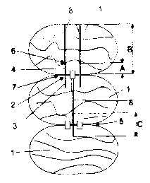
In the wood wall construction made from wooden beams shown, wooden beams 1 are
stacked on top of one another and the subsequent following wooden beams 1 are
connected to one another by screws 2. Here, the wooden beams 1 are connected
to one
another by screws 2 provided at Least at their end regions with threaded
sections ? and 4.
These screws 2 are screwed in from the top ar the bottom side of the wooden
beam l,
without pre-drilling, bridging the mutual attachment area of iwo wooden beams
1, and
extend Over a part A of the height or thickne>s B of the wooden beam I .
Therefore, the
screws 2 are only allocated to the immediate mutual attachment area 5 of two
wooden
beans 1.
The screws are screwed-in without any pre-drilling, so that a considerable
shortening of
the assembly time results. The screws 2 car, be provided with a threaded
section 3 and 4
in the area of their two ends only. However, it is also possible to provide a
continuous
thread over the entire length of the shaft. V~ ithin the scope of the
invention, various
thread forms, various thread leads, and various ratios between the diameter of
the root of
the thread and the outside thread diameter are possible. The construction and
function of
the drilling and/or insertion tip to be provided at one free end can be
carried out in
different manners. The form of a screw hea~3 is variable, too, however, it
must be
provided such that it can easily be mounted within the wooden beam into a
deeply
counter si.u~Ic position. It is also possible th it two threaded sections are
provided with
different thread leads. Although the screwing-in torque is considerably
increased thereby
when screwing into the first wooden beam l, during the engagement of the screw
2 into
-5-
CA 02543560 2006-04-25
WO 2005/061811 PCT/EP2004/053277
the two stacked wooden beams 1 this allows the beams to be pulled against each
other, in
order to increase the mutual pressure. Of course. a surface coating of the
screws used
here is also advantageous. Tn particular, a coating is suitable, which lowers
the screwing
torque of the screws 2. Such coating can be applied in addition to corrosion
protective
coating or the corrosion protective coating can simultaneously cause an effect
reducing
the installation torque.
The screws 2 extend almost egually far into the mutually contacting wooden
beams 1 on
both sides of the mutual attachment area 5. The length C of the screws 2 is
provided
smaller than the height B of the wooden bearns l .
In the mutual attachment area 5 of two wooden beams l, two or more than two
screws 2
are each screwed-in spaced apart from one another, and aligned almost parallel
to one
another.
Here, there is the possibility to perpendicula:-ly screw-in the screws 2 in
reference to the
longitudinal extension of the wooden beams 1 or at an acute angel in reference
to the
longitudinal extension of the wooden beams 1 (see Figs. 5 and 6). Depending on
the
requirements of the mutual extension of the wooden beams 1, the most
beneficial type of
connection can be selected. Therefore, it is also possible to screw-in the
screws 2 either
perpendicular or at an acute angle in reference to the longitudinal extension
of the
wooden beams 1, perhaps subsequently alte°~ating. Further, a variant
provides for the
screws 2 to be screwed-in in pairs with eacr being at an acute angle in
reference to the
longitudinal extension of the wooden beam. 1.
The screws 2 are provided with an interior tool grip 6 at one of their ends,
with the
diameter of the section of the screams 2 surrounding the interior tool grip 6
being provided
with an approximately equal or slightly larf er size than an outside diameter
of the thread.
.6-
CA 02543560 2006-04-25
WO 2005/061811 PCT/EP2004/053277
The screws 2 can be screwed-in with a screw driver bit, with its shaft
adjacent to the
engaging section for contacting the screw 2 0:- a virtual cylindrical shell of
the shaft
having a diameter equal or slightly smaller than the diameter of the section
of the screw 2
surrounding the interior tool grip 6. Further, -his shaft has a length for
covering the
distance of the height B of the wooden beam 1 from the interior toot grip 6 of
the screw 2
to the upper or lower limit and further to the ;crew insert. This way, an
orderly drive of
the screws to a final position can be achieved, without any additional torque
enhancement
being caused by the screwing tool.
When strip-shaped sealing material 7 is used. the screws 2 are arranged
between the edge
regions of the mutual attachment areas 5 of fze sealing material 7 inserted
between the
wooden beams 1
The cross-sectional shape of the wooden beams during the use of the measures
according
to the invention can be designed in multiple ways. For example, wood wall
constmctions
can also be made from wood beams in the shapes naturally formed. Wooden beams
1
sawed into different cross-sectional shapes can also be used with or without
mutual
tongue-and groove formations.
In Fig. l, three bores 8 are discernible, which have been made by screwing-in
the screws
2. Similar bores 8 are discernible in Figs. 2 and 3. .According to the
representation in
Figs. 2 and 3, the bores 8 would appear to b~ arranged over top of one
another; however,
the bores 8 of one beam are actually offset in reference to the bores 8 of the
subsequent
beam by a certain distance, as discernible from Figs. 4-6.
_7_