Note : Les descriptions sont présentées dans la langue officielle dans laquelle elles ont été soumises.
CA 02543670 2006-04-26
PCiKA 20A4/.pp
.99 AUGUST 2005 29-08.05
IMPROVED LEAKAGE CONTROL IN A GAS TURBINE ENGINE
BACKGROUND OF THE INVENTION
Field of the Invention
100011 The present invention relates generally to gas turbine engines. and,
more particularly, to improved leakage control in gas turbine engines.
Description of the Prior Art
[00021 Conventional gas turbine shroud segments are manufactured as a
full ring and later straight-cut into segments to provide.joints which allow
for
thermal growth. The intersegment gap is typically minimized at the highest
power
settings, when the segments are at their maximum operating temperature and
thus
greatest length due to thermal expansion. At lower power, the segments do not
expand as much and the gaps do not close down and thus seals are typically
required. When seals (e.g. feather seals) are not used, these gaps become the
prime leak path for shroud cooling air, which is thermodynamically expensive.
It
is therefore important to minimize the gaps.
[00031 As shown in Fig, Is, the opposed ends of each conventional
shroud segment 5 are straight cut to provide parallel mating faces 7 between
adjacent segments 5. At room temperature each pair of adjacent shroud segments
defines a gap 7. In operation, the shroud segments 5 do not have uniform
temperature distribution (the upstream side of the shroud segments 5 is
typically
exposed to higher temperature than the downstream side thereof). As shown in
Fig. ib, this causes non-uniform thermal expansion and thus non-optimized
intersegment gaps in operating conditions. The shroud segments 5 will be
hotter
upstream and cooler downstream of the gas path, which makes the thermal
expansion uneven and creates a larger gap on the downstream side where air can
escape the cavity defined about the shroud segments 5. As shown in Fig. lb,
the
high thermal expansion will reduce the gap on the upstream side of the shroud
segments 5, whereas the low thermal expansion will leave a larger gap on the
downstream side of the segments 5.
AMENDED .SHEET
CA 02543670 2006-04-25
WO 2005/042926 PCT/CA2004/001810
SUMMARY OF THE INVENTION
[0004] It is therefore an aim of the present invention to provide an
improved shroud for a gas turbine engine members.
[0005] Therefore, in accordance with one aspect of the present invention,
there is provided a gas turbine engine expansion joint, the expansion joint
comprising first and second members having confronting faces defining a gap
therebetween, wherein, at room temperature, the gap varies from one end of the
faces to another end thereof in accordance with the temperature distribution
profile of the first and second members during normal engine operation.
[0006] In accordance with a further general aspect of the present
invention, there is provided a gas turbine engine expansion joint having first
and
second members, the first and second members being provided with confronting
faces defining a gap, which, at room temperature, varies from one end to
another
as a function of a temperature gradient of said members under engine operating
conditions, and wherein said gap is substantially uniform when said first and
second members are subject to said engine operating conditions.
[0007] In accordance with a further general aspect of the present
invention, there is provided a gas turbine engine expansion joint having first
and
second members, the first and second members being provided with confronting
faces defining a gap, the confronting faces being non-parallel at room
temperature
and substantially parallel under conditions of operating temperatures.
[0008] In accordance with a further general aspect of the present
invention, there is provided an annular shroud adapted to surround an array of
turbine blades of a gas turbine engine, the shroud including a plurality of
segments, each pair of adjacent segments having confronting faces defining an
intersegment gap therebetween. At room temperature, the intersegment gap
varies
along a length thereof according to a temperature profile of the segments
during
normal engine operating conditions.
[0009] In accordance with a still further general aspect of the present
invention, there is provided a method for controlling leakage of fluid between
first and second gas turbine engine members subject to non-uniform thermal
-2-
CA 02543670 2006-04-25
WO 2005/042926 PCT/CA2004/001810
growth during engine operation, the first and second members having adjacent
ends defining a gap therebetween, the method comprising the steps of: a)
establishing a temperature distribution profile of the members along the
adjacent
ends thereof during normal engine operation, and b) configuring one of the
adjacent ends in accordance with the temperature distribution profile obtained
in
step a).
BRIEF DESCRIPTION OF THE DRAWINGS
[00010] Having thus generally described the nature of the invention,
reference will now be made to the accompanying drawings, showing by way of
illustration a preferred embodiment thereof, and in which:
[00011] Figs. la and lb are enlarged schematic side views of a number of
shroud segment forming part of an annular shroud adapted to surround a stage
of
turbine blade of a gas turbine engine;
[00012] Fig. 2 is an enlarged simplified elevation view of a gas turbine
engine with a portion of an engine case broken away to show the internal
structures of a turbine section in which an annular segmented shroud, is used
in
accordance with a preferred embodiment of the present invention;
[00013] Fig. 3 is a side cross-section view of a first stage turbine assembly
and the turbine shroud of the gas turbine engine shown in Fig. 2;
[00014] Figs. 4a and 4b are simplified enlarged side views of the shroud
segments respectively illustrating the intersegment gaps at rest, i.e. when
the
engine is not operated, and during normal operating conditions and
[00015] Fig. 5 is a simplified enlarged top view of a vane segment
according to the present invention.
DESCRIPTION OF THE PREFERRED EMBODIMENTS
[00016] Referring to Fig. 2, ' there is shown a gas turbine engine 10
enclosed in an engine case 12. The gas turbine engine 10 is of a type
preferably
provided for use in subsonic flight and comprises a compressor section 14, a
combustor section 16 and a turbine section 18. Air flows axially through the
compressor section 14, where it is compressed. The compressed air is then
mixed
with fuel and burned in the combustor section 16 before being expanded in the
-3-
CA 02543670 2006-04-26
PCT/CA 2004/. 001810
2 0 AUGUST 2005 2 9.0 8.05
turbine section 18 to cause the turbine to rotate and, thus, drive the
compressor
section 14.
[000171 The turbine section 18 comprises a turbine support case 20 secured
to the engine case 12. The turbine support case 20 encloses alternate stages
of
stator vanes 22 and rotor blades 24 extending across the flow of combustion
gases
emanating from the ' combustor section 16. Each stage of rotor blades 24 is
mounted for rotation on a conventional rotor disc 25 (see Fig. 3). Each stage
of
vanes 22 has inner and outer platforms 23. Disposed radially outwardly of each
stage of rotor blades 24 is a circumferentially adjacent annular shroud 26.
[00018] Referring now to Fig. 3, the turbine shroud 26 is disposed radially
outward of the plurality of rotor blades 24. The turbine shroud 26 includes a
plurality of circumferentially adjacent segments 28 (only one of which is
shown in
Fig. 3), each pair of adjacent segments 28 providing an expansion joint. More
particularly, each pair of adjacent'segments 28 defines and intersegment gap
29
(see Figs. 4a and 4b) to provide for the radial expansion and contraction of
the
turbine shroud 26 during normal engine operation. The segments 28 form an
annular ring having a hot gas flow surface 30 (i.e. the radially inner surface
of the
segments) in radial proximity to the radially outer tips of the plurality of
rotor
blades 24 and a radially outer surface 32 against which cooling air is
directed to
cool the shroud 26. Each segment 28 has axially spaced-apart upstream and
downstream sides 34 and 36.
[000191 The hot air which flows generally axially along the radially inner
surface 30 of the shroud 26, as depicted by arrows 38, cools down as it
travels
from the upstream side 34 to the downstream side 36 of the shroud 26, thereby
causing the upstream side 34 of the shroud segments 28 to expand more than the
downstream end 36 thereof, as the latter is exposed to lower temperatures.
This is
represented by arrows 40 and 42 in Fig. 4b, arrow 40 representing the thermal
growth of the upstream side 34 of the shroud segments 28, whereas arrow 42
represents the thermal growth of the downstream side 36 of the segments 28.
[00020[ To compensate for said non-uniform expansion of the segments 28
and thus provides for uniform intersegment gaps during engine operation, it is
-4-
AMENDED SHEET
CA 02543670 2006-04-25
WO 2005/042926 PCT/CA2004/001810
herein proposed, as shown in Fig. 4a, to machine one end of the shroud
segments
28 at an angle so that the intersegment gaps 29 close uniformly in operating
conditions, thereby leaving a smaller gap and, thus, reducing leakage that
would
otherwise negatively affect the performances of the engine 10.
[00021] As shown in Fig. 4a, one end 44 of each shroud segment 28 is cut
slantwise at an angle determined by the thermal expansion gradient observed
between the upstream side 34 and downstream side 36 of the shroud segments 28.
This provides for non-parallel confronting faces 46 at room temperature so
that,
when the engine 10 is not operated, each intersegment gap 29 is more important
on the upstream side 34 than on the downstream side 36 of the shroud 26.
However, during engine operation, the upstream side 34 expands more than the
downstream side 36, thereby bringing the confronting faces 46 in parallel to
one
another while the gap 29 is being closed as a result of the expansion of the
shroud
segments 28. The gaps 29 need not be sized to obtain exactly parallel
confronting
faces 46 during engine operating conditions, but rather any desired margin may
be
left to account for preference in design, etc.
[00022] The angled cut at the end 44 (Fig. 4a) thus allow to compensate for
the axially uneven thermal expansion of the shroud segments 28 and thereby
caused the intersegment gaps 29 to close uniformly in operating conditions.
[00023] The present method has the advantage of not adding extra
hardware or complexity into the engine. It is also inexpensive as this
operation is
typically done by wire-EDM, which is not a cost driver for shroud segments.
[00024] As mentioned hereinbefore, the shroud segments 28 of a gas
turbine engine will always be hotter on the gas path upstream side and
gradually
cooler away from it, resulting in larger intersegment gaps 29 at the
downstream
side of the segments 28. The intersegment gaps 29 are machined wider near the
gas path (i.e. on the upstream side thereof) and thinner near the downstream
side
to better control leakage.
[00025] It is also understood that the present invention can be applied to
any temperature distribution, as opposed to the above-discussed example where
the temperature distribution is linear from one end of the segments to the
other.
-5-
I ,
CA 02543670 2006-04-26
PC= 2004 =001810
29 AUGUST 2005 29-08 .05
For instance, for a parabolic temperature distribution during normal cruise
engine
operation, one end of the segments could be machined with a bowed profile
instead of a straight line in order to obtain the same result, i.e. an
intersegment
gap that closes uniformly at operating temperatures. With this concept, all
temperature profiles can be captured, simple or complex.
[000261 Once the temperature distribution profile of the segments along the
confronting faces thereof under engine operating conditions is established,
then
preferably one end of the segments may be provided appropriately in accordance
with this temperature distribution profile in order to provide for a more-
uniform
closing of the intersegment gap during engine operation. Both ends of the
segments may be profiled according to the present invention, if desired.
[000271 Finally, it is pointed out that the same principle can be applied to
compensate for the radial temperature distribution across the segments.
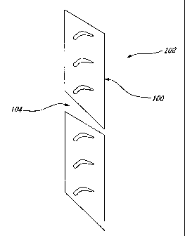
Furthermore, as shown in Figure 5, it could be applied on other types of
parts,
such as the vane segment platforms 100 of vane 102 where the intersegment
leakage through gaps 104 is also important, and may be used with feather or
other
seals to further reduce leakage. As will be understood by the skilled reader
and as
depicted in Figure 5, neither end need be a right angle at room or operating
temperature as depicted in Figure 4a-4b.
[000281 The embodiments of the invention described above are intended to
be exemplary. Those skilled in the art will therefore appreciate that the
forgoing
description is illustrative only, and that various alternatives and
modifications can
be devised without departing from the spirit of the present invention. For
example the profiled surfaces of the present invention may be provided on one
or
more mating surfaces of the present invention and the mating surfaces need not
be linear or continuous, but may be non-linear and/or have as step changes or
other discontinuous. Also, it is to be understood that the segments need not
be
out or machined but may be provided in any suitable manner. The term "room
temperature" is used in this application to refer to a non-operating
temperature,
such temperature being below a= relevant operating temperature of the engine.
-6-
AMENDED SHEET
CA 02543670 2006-04-26
= PCT/CA 2004/.0a 19 1
= 29 AUGUST 2005 29-08.05
Accordingly, the present application contemplates all such alternatives,
modifications and variances.
~I -
-7-
AMENDED SHEET