Note : Les descriptions sont présentées dans la langue officielle dans laquelle elles ont été soumises.
CA 02545600 2006-05-02
DEVICE FOR OPERATING GAS IN VACUUM OR LOW-PRESSURE
ENVIRONMENT AND FOR OBSERVATION OF THE OPERATION
BACKGROUND OF THE INVENTION
1. Field of the Invention
The present invention relates generally to the technology of operating
gasiform
substance in the vacuum or low-pressure environment, and more particularly, to
a
device for operating gas in the vacuum or low-pressure environment and for
observation
of the operation.
2. Description of the Related Art
As far as the technology of microscopic observation is concerned, it is known
that a user can employ an electron microscope with its high-power
magnification to do
scientific research of nanometer substances.
A conventional electron microscope works by utilizing an electron beam to
probe the substance. It is necessary to utilize the accelerated electron beam
by high
voltage and to focus the electron beam by using the electromagnetic lenses to
do the
microscopic observation in a vacuum environment. As shown in FIG 20, an
electron
microscope 61 includes a vacuum specimen chamber 62 for receiving a specimen,
and
an upper pole piece 66 and a lower pole piece 66 both located in the specimen
chamber
62 for ensuring precise focus of the electron beam. The distance between the
two pole
pieces 66 is usually not larger than 1 cm. However, any specimen received in
the
specimen chamber 62 must be a solid, not a fluid such as liquid or gas, to
allow
observation in such vacuum environment, since a fluid specimen is subject to
immediate boiling, volatilization, or the like.
To overcome the above problem and to allow the specimen received in the
t
CA 02545600 2006-05-02
electron microscope to coexist with a specific gas, an environment chamber for
controlling vapor was invented in 1976 (Hui S. W. et al., Journal of Physics E
9, 69,
1976). The modified electron microscope 71, as shown in FIGS. 21 and 22,
includes a
heightened specimen chamber 72, a water tank 74 mounted inside the specimen
chamber 72, and an environment chamber 76. The environment chamber 76 has two
spacers 762 partitioning its center off into a vapor layer 764 and two buffer
layers 766
located respectively below and above the vapor layer 764. The water tank 74
has a
temperature-controllable vent pipe 741 connected with the vapor layer 764 for
offering
vapor of the same temperature as that of the environment chamber 76 to avoid
condensation resulting from the entry of the vapor into the vapor layer 764.
The two
spacers 762 and top and bottom sidewalls of the environment chamber 76 are
parallel to
one another, each having an aperture 763. The apertures 763 are coaxial with
one
another for penetration of the electron beam. The environment chamber 76
further has a
specimen tube 767 extending outwards from the vapor layer 764, a specimen
holder 768
extending through the specimen tube 767 into the vapor layer 764 from outside,
and an
0-ring 769 sealing space between the specimen holder 768 and the vapor layer
764 for
insulation between the vapor layer 764 and the outside.
During operation of the electron microscope 71, the vapor inside the water
tank
74 keeps flowing into the vapor layer 764. In the meantime, the two buffer
layers 766
are evacuated to pump out the vapor leaking from the vapor layer 764,
preventing the
vapor from flowing out of the two buffer layers 766 through the two apertures
763 of
the environment chamber 76. Thus, the gas pressure inside the vapor layer 764
of the
environment chamber 76 can be maintained at 50 torrs or so.
Although the aforementioned prior art can enable generation of extremely
low-pressure vapor in the vapor layer, there are still some drawbacks for
improvement.
2
CA 02545600 2006-05-02
1. It is necessary to alter the original design of the electron microscope.
However, disassembling and assembling the electron microscope is very
complicated,
requiring experts to do it well, and is very costly and subject to damage to
electron
microscope. Thus, such invention still cannot be applied to mass production.
2. Heightening the specimen chamber of the electron microscope may result
in alteration of the focal length of the electron beam to further cause
aberration and loss
of resolution.
3. Increasing the gas pressure inside the vapor layer will result in leakage
of
the gas into the vacuum zone, as shown in FIG. 22, disabling the operation of
standard
atmospheric pressure inside the vapor layer. Although dramatically enhancing
evacuation for the buffer layers 766 can overcome this problem, the high-speed
pumping rate caused by the enhanced evacuation may result in strong
turbulence,
causing multiple scattering caused by the electrons impinging the gas
molecules and
further disabling successful imaging of the electron beam or experiment of
electron
diffraction.
Another research group for modification of the electron microscope presented
an experiment of observation of gasiform and solid chemical reactions under
the
electron microscope in 2002 (Gai P. L., Microscopy & Microanalysis 8, 21,
2002). Such
design is similar to the aforementioned invention, but has the following
drawbacks.
Because the space between the pole pieces inside the electron microscope is
about 1 cm
high in size and treated as a gas chamber, if the gas pressure inside the
environment
chamber keeps increasing, the multiple scattering of the electrons will become
excessive. As far as this design of the environment chamber of 1 cm in height
is
concerned, while the gas pressure inside the environment chamber reaches the
standard
atmospheric pressure, the multiple scattering of the electrons can disable
successful
3
CA 02545600 2006-05-02
imaging of the electron beam or experiment of electron diffraction.
There were also some similar designs/experiments, such as Lee T. C. (Lee T. C.
et al., Rev. Sci. Instrum. 62, 1438, 1991), Robertson I. M. (Robertson I. M.
at al.,
Microscopy Research & Technique 42, 260, 1998), Sharman R. (Sharman R.,
Microscopy & Microanalysis 7, 494, 2001), etc. However, they all exhibit the
same
problem of multiple scattering of the electrons while operating the gas
chamber at the
standard atmospheric pressure.
In addition, in Hui's design, the whole environment chamber is fixed inside
the
microscope, such that it is very difficult to enable and operate the electron
beam to pass
through the coaxial apertures of the environment chamber while the environment
chamber is installed in the microscope. In Gai's design, it also had the
similar problem
that it is difficult to align the two apertures on the top and bottom pole
pieces. Further,
the environment chamber of Hui's design is fixed to the lower pole piece, such
that the
vertical position of the whole environment chamber fails to be adjusted and
then it
failed to interconnect the focus range for accurate focus.
In view of the aforementioned drawbacks of the prior art, the inventor of the
present invention finally overcomes them to easily enable the electron beam of
the
electron microscope to pass through the device of the present invention and
enable the
device to be located inside the focus range of the electron microscope for
more
convenient focus operation.
SUMMARY OF THE INVENTION
The first objective of the present invention is to provide a device for
operating
gas in the vacuum or low-pressure environment and for observation of the
operation.
The device provides the environment for observation of gas without alteration
of
original structure of the electron microscope.
4
CA 02545600 2006-05-02
The second objective of the present invention is to provide a device for
operating gas in the vacuum or low-pressure environment and for observation of
the
operation. The device can control parameters of pressure of the gas more
easily than the
prior art to reach higher pressure.
The third objective of the present invention is to provide a device for
operating
gas in the vacuum or low-pressure environment and for observation of the
operation.
The device does not affect the resolution of the electron microscope.
The fourth objective of the present invention is to provide a device for
operating gas in the vacuum or low-pressure environment and for observation of
the
operation. The device can be more easily operated and more conveniently
assembled.
The foregoing objectives of the present invention are attained by the present
invention, which includes a housing. The housing has a thinner part formed at
a side
thereof, and at least one spacer mounted therein for partitioning off its
inside into a gas
chamber and at least one buffer chamber outside the gas chamber. The gas
chamber has
two inner apertures provided on the spacer above and below the gas chamber.
The
housing has two outer apertures provided respectively on a top side thereof
and a
bottom side thereof. All of the inner and outer apertures are coaxial with one
another
and located on the thinner part. The housing has a pumping port for
communication
with the buffer chamber, and a gas inlet for communication with the gas
chamber.
Therefore, the device of the present invention can provide the environment for
observation of the gas, being conveniently assembled and easily operated,
without
alteration of the original structure of the electron microscope.
BRIEF DESCRIPTION OF THE DRAWINGS
FIG I is a perspective view of a first preferred embodiment of the present
invention.
5
CA 02545600 2006-05-02
FIG. 2 is a sectional view of the first preferred embodiment of the present
invention.
FIG. 3 is a schematic view of the first preferred embodiment of the present
invention mounted inside an electron microscope.
FIG. 4 is a sectional view of the first preferred embodiment of the present
invention, in which a liquid-gas container is located outside the housing.
FIG. 5 is a sectional view of a second preferred embodiment of the present
invention.
FIG. 6 is a partially sectional view of a third preferred embodiment of the
present invention.
FIG. 7 is a perspective view of the third preferred embodiment of the present
invention.
FIG 8 is a top sectional view of the third preferred embodiment of the present
invention.
FIG 9 is a sectional view of a fourth preferred embodiment of the present
invention.
FIG. 10 is an enlarged view of FIG 9.
FIG. 11 is a sectional view of a fifth preferred embodiment of the present
invention mounted inside the electron microscope.
FIG. 12 is an exploded sectional view of a sixth preferred embodiment of the
present invention.
FIG. 13 is a sectional view of the sixth preferred embodiment of the present
invention.
FIG. 14 is a perspective view of the housing of a seventh preferred embodiment
of the present invention.
6
CA 02545600 2006-05-02
FIG. 15 is a sectional view of the seventh preferred embodiment of the present
invention.
FIG. 16 is a sectional view of an eighth preferred embodiment of the present
invention.
FIG. 17 is a sectional view of a ninth preferred embodiment of the present
invention.
FIG. 18 is a sectional view of a tenth preferred embodiment of the present
invention.
FIG. 19 is a sectional view of an eleventh preferred embodiment of the present
invention.
FIG 20 is a schematic view of the specimen chamber of the conventional
electron microscope.
FIG. 21 is a schematic view of the conventional environment chamber mounted
to the reconstructed electron microscope.
FIG 22 is a sectional view of a part of the conventional environment chamber.
DETAILED DESCRIPTION OF PREFERRED EMBODIMENTS
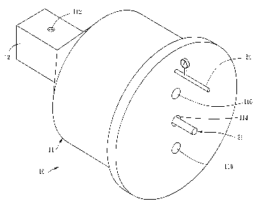
Referring to FIGS. 1-3, a device 10 for operating gas in the vacuum or
low-pressure environment and for observation of the operation, constructed
according to
a first preferred embodiment of the present invention, is composed of a
housing 11, a
temperature-controllable liquid-gas container 21, a specimen holder 31, and a
pumping
device 41, in cooperation with an electron microscope 91. The electron
microscope 91
has a specimen chamber 92 therein, two pole pieces 96 mounted respectively at
upper
and lower sides of the specimen chamber 92, and an insertion port 94 located
at a side
of the specimen chamber 92 for inserting the device 10.
The housing 11 includes a thinner part 12 formed at a side thereof, and a
7
CA 02545600 2006-05-02
plurality of spacers 14 mounted in an interior space within the housing 11.
The thinner
part has a thickness that is substantially smaller than the distance between
the two pole
pieces 96 of the specimen chamber 92. The distance between the pole pieces 96
is
generally not larger than 1 cm. The spacers 14 partition the interior space of
the housing
11 into a gas chamber 16 and two buffer chambers 18 located respectively above
and
below the gas chamber 16. Inner apertures 142 are formed in the spacers
respectively at
top and bottom sides of the gas chamber 16. The housing 11 includes two outer
apertures 112 formed respectively at top and bottom sides thereof, the outer
apertures
112 being coaxially aligned with the inner apertures 142. All of the inner and
outer
apertures 142 and 112 are located on the thinner part 12 of the housing 11. An
insertion
slot 114 is defined in the housing 11 corresponding to the gas chamber 16 for
communication between the gas chamber 16 and the outside of the housing 11.
The
housing 11 has two pumping ports 116 formed therein for communication with the
buffer chambers 18, and a gas inlet 166 forrned therein for communication with
the gas
chamber 16. Each of the inner apertures 142 has a diameter of 10-200 m, and
each of
the outer apertures 112 has a diameter of 20-800 m. Each inner aperture 142 is
smaller
in diameter than each outer aperture 112. In the present embodiment, the
diameter of the
inner apertures 142 is 100 m, and the diameter of the outer apertures is 200
m.
The temperature-controllable liquid-gas container 21 is located inside one of
the buffer chambers 18, including a temperature-controllable vent pipe 22 and
a
temperature-controllable conduit 24. The vent pipe 22 is connected with the
gas inlet
166 for transferring a gas inside the liquid-gas container 21 to the gas
chamber 16,
wherein the temperature of the gas is identical to that of the gas chamber 16.
The gas
can be, subject to requirement, nitrogen, oxygen, helium, carbon dioxide,
other gas, a
vapor generated from a liquid inside the liquid-gas container 21, or a
combination of the
8
CA 02545600 2006-05-02
aforementioned gases.
The vent pipe 22 extends into the liquid-gas container 21, having a distal end
located higher than the level of the liquid inside the liquid-gas container
21, for
providing the liquid vapor of this liquid in the liquid-gas container 21. The
conduit 24
provides communication between the liquid-gas container 21 and the outside of
the
housing 11, for offering liquid from outside or directly offering other gas,
like helium or
nitrogen, etc., which must be heated to the same temperature as the liquid-gas
container
21 in advance to prevent the liquid vapor inside the liquid-gas container 21
from
condensation caused by the cold gas infused from the conduit 24. In this
embodiment,
the liquid-gas container 21 contains water of the same temperature as that of
the gas
chamber 16 for providing the gas chamber 16 with the pressure of saturated
water vapor
in such temperature.
The specimen holder 31 includes a target stage 32 for loading a specimen. The
target stage 32 has an opening 34 and a seal 36. The specimen holder 31 is
inserted
through the insertion slot 114 to be received in the gas chamber 16. The
opening 34 is
coaxial with the inner and outer apertures 142 and 112. The seal 36 seals a
gap formed
between the specimen holder 31 and the gas chamber 16.
The pumping device 41 is connected with the two pumping ports 116 for
pumping out, or evacuating, the two buffer chambers 18.
Referring to FIGS. 2 and 3, the device 10 of the present invention can be
cooperatively mounted inside the specimen chamber 92 of the electron
microscope 91
by inserting the housing through the port 94 of the electron microscope 91.
Because the
height of the thinner part 12 is smaller than the distance between the two
pole pieces 96,
the thinner part 12 can be positioned between the two pole pieces 96, enabling
the inner
and outer apertures 142 and 112 for alignment with the path of the electron
beam of the
9
CA 02545600 2006-05-02
electron microscope 91. The specimen holder 31, loaded with a specimen 99, is
inserted
from the insertion slot 114 into the gas chamber 16, enabling the specimen 99
for
alignment with the inner and outer apertures 142 and 112.
The temperature inside the housing 11, the spacers 14, the liquid-gas
container
21, and the specimen holder 31 is controlled to enable the temperature of the
gas
infused from the vent pipe 22 to be identical to that of the gas chamber 16,
the specimen
holder 31, and the target stage 32. When the gas chamber 16 is supplied with
gas of
predetermined pressure by the liquid-gas container 21, and the two buffer
chambers 18
are evacuated by the pumping device 41, if any gas leaks out of the gas
chamber 16
through the inner apertures 142 into the two buffer chambers 18, the leaking
gas will be
evacuated from the two buffer chambers 18 without exhausting through the outer
apertures 112 outside the housing 11. Controlling the pumping rate of the
pumping
device 41 and the gas infusion rate of the liquid-gas container 21 can keep
the gas inside
the gas chamber 16 in a predetermined pressure to enable operating the gas
inside the
gas chamber 16 in the vacuum environment. The electron beam of the electron
microscope 91 passing through the inner and outer apertures 142 and 112 can
detect the
specimen 99 to enable observation for the user.
The liquid-gas container 21 can be alternatively mounted outside the housing
11, as shown in FIG. 4, and the vent pipe 22 extended out of the housing 11
for
communication between the liquid-gas container 21 and the gas chamber 16. Such
structure not only has the same function as that mounted inside the housing 11
but also
provides a range of unsaturated vapor pressure. Because the temperature of the
liquid-gas container 21 mounted outside of the housing 11 can be controlled to
be lower
than, instead of the same as, that of the gas chamber 16 and the target stage
32, an
environment of vapor pressure lower than the saturated one may be generated
around
CA 02545600 2006-05-02
the specimen loaded on the target stage 32. In addition, such structure
enables the user
to conveniently operate the liquid-gas container 21. For example, the user can
switch off
the infusion of the gas at any time and accurately observe the level of the
liquid and the
supply amount of the liquid.
Referring to FIG. 5, a device 50 for operating gas in the vacuum or
low-pressure environment and for observation of the operation, constructed
according to
a second preferred embodiment of the present invention, is similar to the
first
embodiment, but has differences as follows.
The housing 11' is partitioned off additionally into an upper buffer chamber
181' and a lower buffer chamber 181', which are located respectively above and
below
the two buffer chambers 18'. Additional pumping ports are formed in the
housing 11',
there being now the two pumping ports 116' as described in the previous
embodiment,
and two additional pumping ports 117', wherein the two buffer chambers 18'
correspond respectively to the two pumping ports 116', and the upper and lower
buffer
chambers 181' correspond respectively to the two pumping ports 117'. Two
buffer
apertures 144' are formed respectively in the two spacers 14' located
respectively
between the upper buffer chamber 181' and the buffer chamber 18' and the lower
buffer
chamber 181' and the buffer chamber 18', the buffer apertures 144' being
coaxial with
the inner and outer apertures 142' and 112'. Each of the two buffer apertures
144' has a
diameter of 10-400 m, the diameter being greater than the diameter of the
inner
aperture 142' and less than the diameter of the outer aperture 112'. The
device 50
employs the four buffer chambers 18' and 181', rather than two as described in
the
previous embodiment, to achieve the effect of multilayered depressurization
through the
differential pumping and also a broader operation range of the pumping rates
of the four
buffer chambers 18' and 181', and to enable the gas chamber 16' to have a much
larger
11
CA 02545600 2006-05-02
pressure than that achieved by the only two buffer chambers 18 in the previous
embodiment. Under such circumstance, the pumping rate of the upper and lower
buffer
chambers 181'must be greater than that of the two buffer chambers 18'.
The second embodiment is similar in operation to the first embodiment.
Because the buffer chambers in the second embodiment are twice in number as
those of
the first embodiment, the controllable range of the differentially pumping
rate of the
buffer chambers is greater and more flexible. In this embodiment, the user can
control
the pumping rates of the buffer chambers 18' and 181' respectively at 160L/sec
and
240L/sec or above, to increase the gas pressure inside the gas chamber 16 up
to 760
torrs, in the environment of gas or a gas and vapor mixture, but still
preventing the gas
from leaking through the outer apertures 112' into the vacuum section outside
the
housing 11'.
Referring to FIGS. 6-8, a device 60 for operating gas in the vacuum or
low-pressure environment and for observation of the operation, constructed
according to
a third preferred embodiment of the present invention, is similar to the
aforementioned
first embodiment, but has differences as follows.
There is an inclined spacer 19 mounted in each of the buffer chambers 18" for
partitioning off each buffer chamber 18" into two auxiliary buffer chambers
192. Each
of the inclined spacers 19 has a buffer aperture 196 coaxially aligned with
the inner and
outer apertures 142" and 112". Each of the auxiliary buffer chambers 192
corresponds
to one of the pumping ports 116" located in the housing 11" for evacuation of
the
auxiliary buffer chambers 192.
In this embodiment, the inclined spacers 19 enable the housing 11 " to have
more buffer chambers 18" without heightening the housing 11". In other words,
the
device 60 of this third embodiment has two more buffer chambers than the
device 10 of
12
CA 02545600 2006-05-02
the first embodiment. As with the additional buffer chambers 181' in the
second
embodiment, the structure of the auxiliary buffer chambers based on the
principle of
multilayered differential pumping not only increase the gas pressure inside
the gas
chamber 16", up to 760 torrs as indicated in the second embodiment, but also
enlarge
the controllable range of the pumping rates of the buffer chambers thereby
making it
more flexible.
Referring to FIGS. 9 and 10, a device 80 for operating gas in the vacuum or
low-pressure environment and for observation of the operation, constructed
according to
a fourth preferred embodiment of the present invention includes a housing 81
and a
specimen holder 85.
The housing 81 has a thinner part 82 formed at one side and two spacers 83
partitioning off its inside into a buffer chamber 821 and two additional
buffer chambers
822 formed respectively above and below the buffer chamber 821. Each of the
two
spacers 83 has a buffer aperture 831 between the buffer chamber 821 and the
additional
buffer chamber 822, located at a top (bottom) side of the buffer chamber 821.
The
housing 81 has two outer apertures 811 formed respectively at top and bottom
sides
thereof for communication with the vacuum section outside the housing 81, an
insertion
slot 812 in communication with the buffer chamber 821, two pumping ports 813
corresponding to the buffer chamber 821, and two additional pumping ports 814
corresponding to the two additional buffer chambers 822.
The specimen holder 85 is mounted into the buffer chamber 821 through the
insertion slot 812, having a gas infusion pipe 851 therein. A gas box 86 has
an opening
861 at one end (open end), and the open end is partially inserted in a front
end of the
specimen holder 85, in communication with the gas infusion pipe 851, and fixed
by an
adhesive 862. A retaining wall 852 is formed around the gas box 86, and a gas
inlet 853
13
CA 02545600 2006-05-02
is defined in the specimen holder 85 in communication with the gas infusion
pipe 851.
The opening 861 or the gas box 86 communicates with the gas infusion pipe 851.
The
gas box 86 has a target stage 87 formed therein for loading a specimen, a gas
chamber
863 formed therein and covering the target stage 87, and two inner apertures
864
formed on a top side and a bottom side of the gas box 86 for communication
with the
buffer chamber 821. The inner, outer, and buffer apertures are coaxially
aligned.
The operation of the fourth embodiment is similar to that of the second
embodiment such that no further recitation is necessary. It is to be noted
that the
temperature of the infused gas through the gas infusion pipe 851 must be lower
than or
equal to that of a sidewall of the gas infusion pipe 851 to prevent the
infused vapor from
condensation inside the gas infusion pipe 851.
In the fourth embodiment, the gas chamber 863 is formed inside the specimen
holder 85 to transform the gas chamber 863 defined in the first embodiment
into a
buffer chamber to have one more buffer chamber than the first embodiment.
Increasing
the number of the differentially pumped buffer chambers without heightening
the
housing 81 can not only enhance the pressure of the gas chamber up to 760
torrs, but
also enables a larger and more flexible range of maneuverability of pumping
rate for the
buffer chambers.
Referring to FIG. 11, a device alO for operating gas in the vacuum or
low-pressure environment and for observation of the operation is constructed
according
to a fifth preferred embodiment of the present invention, wherein the vacuum
or
low-pressure environment is the specimen chamber 92 located between the two
pole
pieces 96 inside the electron microscope 91. A focus range Ra is formed on an
imaginary axis G defined by the electron beam passing through between the two
pole
pieces 96. The device a10 includes a housing al l and a spacer a21.
14
CA 02545600 2006-05-02
The housing a 11 has at least one buffer chamber a 12 and an outer aperture a
14
formed at each of a top side thereof and a bottom side thereof.
The spacer a21 defines a gas chamber a22 enclosed thereby, having two inner
apertures a24 formed thereon and abutting a top side of and a bottom side of
the gas
chamber a22 respectively. The distance between the two inner apertures a24 is
smaller
than 0.7mm.
The housing all and the spacer a21 can be combined together. In this
embodiment, the gas chamber a22 enclosed by the spacer a21 is located inside
the
interior space of the housing al l and the buffer chamber a12 formed between
the spacer
a21 and the housing a 11. The inner apertures a24 and the outer apertures a 14
are
coaxially aligned with one another. The imaginary axis G runs through the
inner and
outer apertures a24 and a14. The buffer chamber a12 covers the upper inner
aperture
a24. The lower inner aperture a24 is applied with a pressure regulation a28
which is an
extension of the buffer chamber a12. In other words, the buffer chamber a12
covers the
two inner apertures a24. The housing al I has two pumping ports al6 in
communication
with the buffer chamber a12. The spacer a21 has a gas inlet a26 in
communication with
the gas chamber a22. The gas chamber a22 overlaps the focus range Ra, and
namely, a
highest position that the housing al l is located in the specimen chamber 92
is that a
bottom side of the gas chamber is lower than or equal to a top end of the
focus range Ra,
and a lowest position that the housing al l is located in the specimen chamber
92 is that
a top side of the gas chamber is higher than or equal to a bottom end of the
focus range
Ra. In this embodiment, the gas chamber a22 is located at a midsection of the
focus
range Ra. The distance between the two inner apertures a24 is smaller than
0.7mm to
enable more clear observation and to avoid unclear image due to electron
inelastic
scattering resulted from extremely thick gas layer.
CA 02545600 2006-05-02
The operation of the fifth embodiment is similar to the first embodiment,
having difference recited as follows. The gas chamber a22 must overlap the
focus range
Ra to enable the specimen inserted into the gas chamber a22 to be effectively
focused
for further observation.
Referring to FIGS. 12 and 13, a device b10 for operating gas in the vacuum or
low-pressure environment and for observation of the operation, constructed
according to
a sixth preferred embodiment of the present invention, is similar to the fifth
embodiment, having difference recited below.
The spacer b21 is separable from the housing b 11, and namely, the gas chamber
b22 enclosed by the spacer b21 is separable from the housing b 11 and the
buffer
chamber b12. In this embodiment, the spacer b21 is formed on a specimen holder
b25
and the gas chamber b22 is formed between the spacer b21 and the specimen
holder b25.
At least one sealing piece b29, like 0-ring, is mounted to seal among the
specimen
holder b25, the spacer b2 1, and the housing b 11.
While the sixth embodiment is in operation, the spacer b21 is placed into the
housing bl l and the sealing piece b29 is located among the specimen holder
b25, the
spacer b21, and the housing bll for the sealing potency. The rest of the
operation,
including gas evacuation and infusion, is the same as the aforementioned
embodiment,
such that no further description is necessary.
Referring to FIGS. 14 and 15, a device cl0 for operating gas in the vacuum or
low-pressure environment and for observation of the operation, constructed
according to
a seventh preferred embodiment of the present invention, is similar to the
sixth
embodiment, having difference recited below.
In addition to the gas chamber c22 enclosed by the spacer c21 in the specimen
holder c25, the housing cl l further includes a plurality of spacers c17
mounted therein
16
CA 02545600 2006-05-02
for partitioning the interior space thereof additionally into an inner buffer
chamber c 18
formed inside the buffer chamber c12. Two buffer apertures c19 are formed onto
the
spacers c 17 and located at a top side and a bottom side of the inner buffer
chamber c 18
respectively. The buffer, inner, and outer apertures 69, c24, and c14 are
coaxially
aligned with one another. The housing cll further includes two pumping ports
c181
formed at bilateral sides of the inner buffer chamber c18 respectively, two
gas passages
c182 in communication with the two pumping ports c181, and an insertion hole
clll
formed at a front side thereof and in communication with the inner buffer
chamber c18.
The gas chamber c22 formed by the spacer c21 on the specimen holder c25 is
inserted
into the housing cl l through the insertion hole c111.
The seventh embodiment has one more inner buffer chamber c18 than the sixth
embodiment to have the potency of the increased buffer chambers like that in
the second
embodiment. The operation of the seventh embodiment is the same as that of the
sixth
embodiment, and so are the gas evacuation and infusion, such that no further
recitation
is necessary.
Referring to FIG. 16, a device d10 for operating gas in the vacuum or
low-pressure environment and for observation of the operation, constructed
according to
an eighth preferred embodiment of the present invention, is similar to the
sixth
embodiment, having difference recited below.
In addition to the gas chamber d22 enclosed by the spacers d21 in the specimen
holder d25, a spacer d27 is mounted outside the specimen holder d25 to enclose
the gas
chamber d22, forming an inner buffer chamber d28 between the spacer d27 and
the
spacer d21. Two buffer apertures d29 are formed on the spacer d27,
corresponding to a
top side and a bottom side of the inner buffer chamber d28 respectively. The
buffer
apertures d29 are coaxially aligned with the inner apertures d24. The spacer
d27 is
17
CA 02545600 2006-05-02
separable from the housing dl l and is connected with the housing dl l in
operation.
The eighth embodiment has one more inner buffer chamber d28 than the sixth
embodiment and the inner buffer chamber d28 is formed on the specimen holder
d25.
Because the operation of the eighth embodiment is the same as those of the
sixth and
seven embodiments, wherein the pumping ports or the gas inlets can be located,
as it
depends, at the bilateral sides or, as the same in the seventh embodiment, at
the front
and rear sides of the inner buffer chamber d28, no more description is
necessary.
Referring to FIG 17, a device elO for operating gas in the vacuum or
low-pressure environment and for observation of the operation, constructed
according to
an ninth preferred embodiment of the present invention, is similar to the
eighth
embodiment, having difference recited below.
The housing el l encloses the spacers e2 1, and namely, the housing el 1 and
the
spacers e21 are combined together on a specimen holder e25. The gas chamber
e22 and
the inner buffer chamber e28 are formed by the enclosure of the spacers e2 1.
The buffer
chamber e12 is formed between the housing ell and the spacer e2l located
further
outside than the other. The inner, buffer, and outer apertures e24, e29, and
e14 are
coaxially aligned.
The operation of the ninth embodiment is the same as that of the second
embodiment, including the gas evacuation and infusion, so no more description
is
necessary.
Referring to FIG. 18, a device flO for operating gas in the vacuum or
low-pressure environment and for observation of the operation, constructed
according to
an tenth preferred embodiment of the present invention, is similar to the
fifth
embodiment, having difference recited below.
The pressure regulation f28 is defined as a film mounted to and sealing the
18
CA 02545600 2006-05-02
inner aperture f24 located lower than the other, being different from that
(connected
with the buffer chamber) of the fifth embodiment. In the tenth embodiment, the
buffer
chamber f12 covers the inner aperture f24 located higher than the other.
Accordingly,
the pressure regulation f28 can prevent the gas inside the gas chamber f22
from
exhausting through the lower inner aperture f24, thus attaining the pressure
regulation
and buffering potency.
The operation of the tenth embodiment is the same as that of the fifth
embodiment, including the gas evacuation and infusion, so no further
recitation is
necessary.
Referring to FIG. 19, a device glO for operating gas in the vacuum or
low-pressure environment and for observation of the operation, constructed
according to
an eleventh preferred embodiment of the present invention, is similar to the
fifth
embodiment, having difference recited below.
The pressure regulation g28 is defined as a film mounted to and sealing the
lower outer aperture g14. The buffer chamber g12 covers the two inner
apertures g24.
Accordingly, the pressure regulation g28 can prevent the gas inside the buffer
chamber
g12 from exhausting through the lower outer aperture g14, thus attaining the
pressure
regulation and buffering potency.
Because the operation of the eleventh embodiment is the same as those of the
fifth embodiment, including the gas evacuation and infusion, wherein the
pumping ports
or the gas inlets can be located, as it depends, at the bilateral sides or, as
the same in the
seventh embodiment, at the front and rear sides of the inner buffer chamber
d28, no
more description is necessary.
In conclusion, the present invention includes advantages as follows.
1. Because the present invention is one-piece and can be directly inserted
into
19
CA 02545600 2006-05-02
the predetermined insertion port located on the electron microscope without
alteration
of the original design of the microscope, it overcomes the problems that
installing the
conventional environment chamber of the prior art into the electron microscope
is quite
complex and difficult for mass production. Installing the present invention is
quite
simple, requiring only simple training before its operation. Additionally, the
installation
is low-cost and harmless to the electron microscope, thus enabling mass
production in
the industries.
2. Because it is easy to install the present invention and the user can easily
externally control parameters like pumping rate and gas supply rate, it is not
necessary
to disassemble the electron microscope for adjustment of the parameters and it
is easier
to control the parameters of the gas pressure.
3. Because it is not necessary to adjust the height of the specimen chamber of
the electron microscope for the present invention, it will not cause
alteration of the focal
length of the electron beam to further eliminate the aberration and loss of
resolution as
in the prior art.
4. In the prior arts, the distance of the path of the electron beam through
the gas
is about or greater than the distance between the two pole pieces. The thinner
part of the
present invention enables the gas chamber to be very thin to greatly reduce
the distance
that the electron beam passes through the gas, such that no loss of resolution
caused by
the multiple scattering of the electrons results from the electron beam
impinging too
many gas molecules. The multilayered and differentially pumped buffer chambers
mounted outside the gas chamber of the present invention can allow proper
pressure
drop in each of different buffer chambers and enlarge the controllable range
of the rate
of pumping the gas out of the buffer chambers. Thus, the multilayered pressure
buffering (depressurization) by differentially pumping those buffer chambers
can
CA 02545600 2006-05-02
enhance the gas pressure inside the gas chamber to reach the standard
atmospheric
pressure.
21