Note : Les descriptions sont présentées dans la langue officielle dans laquelle elles ont été soumises.
CA 02546249 2010-07-21
Jet Dispersing Device
[Technical Field]
[0001]
The present invention concerns a jet dispersing device
suitable to promote mixing of a plurality of fluids such as a
two-component mixed type coating material comprising a main
ingredient and a curing ingredient by simultaneously jetting
and dispersing the same as fine particles.
[Background Art]
[0002]
Jet dispersing device have been used for in-line
mixing less miscible coating material ingredients such as
aqueous 2-component polyurethane type coating materials
comprising a main agent and a curing agent to each other.
[Patent Document 1] JP-A No. 7-331170
[0003]
Fig. 4 shows such an existent jet dispersing device 51
in which a partition wall 54 for partitioning a flow inlet
53in and a flow outlet 53out in a tubular housing 52.
1
CA 02546249 2010-07-21
The partition wall 54 is formed by extending a
bottomed cylindrical tubular member 56 from a central opening
to the flow inlet 53in of a flat plate-flange 55, and fine
nozzle holes 57, each with a diameter of about 0.5mm are
formed and opposed in the circumferential surface of the
tubular wall 56a.
[0004]
Fig. 5 shows a coating material supply system 61 in
which the jet dispersing device 51 is disposed in an in-line
arrangement. After storing a main agent and a curing agent
supplied from a main agent supply source 62A and a curing
agent supply source 62B in high pressure cylinders 63A, 63B,
when they are supplied under high pressure at a flow rate in
accordance with the mixing ratio to the jet dispersing device
51, the main agent and the curing agent merged on the side of
the flow inlet 53in of the jet dispersing device 51 are
jetted to the down stream upon passage through the nozzle.
holes 57, toward the flow outlet 53out and they are
dispersed as fine particles respectively and mixed under
emulsification.
Accordingly, when the mixed coating material is
supplied to a coating machine 64, the main agent and the
curing agent which are difficult to be mixed can be coated in
2
CA 02546249 2010-07-21
a state being mixed uniformly.
[0005]
Then, in the coating: material supply system 61 as
described above, it is necessary that the coating material
flow channel 65 downstream of the meeting place for the main
agent and the curing agent has to be cleaned frequently in
order to prevent a residual coating material from curing.
However, even when a cleaning fluid such as a cleaning
liquid or cleaning air is supplied under pressure from the
flow inlet 53in to the flow outlet 53out of the jet
dispersing device 51, since fine nozzle holes 57, formed
in the partition wall 54 gives a flow channel resistance to
lower the flow speed of the cleaning fluid, it requires a
long time for cleaning and increase the amount of the
cleaning liquid and the cleaning air, to bring about a
problem that efficient cleaning is impossible.
[0006]
While it has been attempted to increase the pressure
of supplying the cleaning liquid and the cleaning air to
thereby shorten the cleaning time, this not only requires a
high pressure pump for supplying the cleaning liquid and the
cleaning air but also complicates the facility such as by the
3
CA 02546249 2011-10-21
use of hoses and connectors acceptable for pressure proofness
and, on the. other hand, the cleaning time can not be
shortened by so much.
(Disclosure of the Invention]
(0007]
In view of the above, it is a technical subject of the
present invention to adapt such that a cleaning fluid can be
caused to flow at a flow speed to some extent in a flow
channel of a jet dispersing device formed with fine nozzle
holes for jetting and dispersing a liquid even in a case
where the dispersing device is disposed in an in-line
arrangement thereby capable of cleaning the flow channel
efficiently, rapidly, and reliably.
[0008]
For solving a subject of the present invention, the present invention
provides a jet dispersing device in which a partition wall
for partitioning a high pressure region having a flow inlet
and a low pressure region having a flow outlet is formed with
nozzle holes for jetting a liquid from the high pressure
region to the low pressure-region and dispersing the same as
fine particles characterized in that a cleaning fluid
4
CA 02546249 2011-10-21
communication port of a larger opening area compared with the
that of the nozzle hole is formed in the partition wall, and
a valve mechanism for opening and closing the communication
port is provided.
[Effect of the Invention]
[0009]
In the jet dispersing device according to the
invention, when a cleaning fluid is supplied by opening the
cleaning fluid communication port formed in the partition
wall by the valve mechanism, since the cleaning fluid flowing
from the high pressure region to the low pressure region
flows passing through the cleaning fluid communication port
of the large opening area compared with that of the nozzle
hole, the cleaning fluid does not undergo the resistance
given by the nozzle holes, can be caused to flow at a flow
rate necessary for cleaning, and can rapidly and reliably
clean the jet dispersing device and the flow channel in which
the sprayer is disposed in the in-line arrangement.
According to an aspect of the present invention there
is provided a jet dispersing device, comprising:
a high pressure region having a flow inlet;
a low pressure region having a flow outlet;
a partition wall positioned within the high pressure
region such that the high pressure region is partitioned
from the low pressure region, wherein the partition wall has
at least one nozzle hole configured to jet a liquid from the
high pressure region to the low pressure region such that
the liquid is dispersed as fine particles, and wherein the
partition wall has a cleaning fluid communication port
CA 02546249 2011-10-21
5a
having an opening area which is larger than an opening area of
the at least one nozzle hole; and
a valve mechanism configured to open and close the cleaning
fluid communication port.
[Brief Description of the Drawings]
,[0028]
[Fig 1(a)] is an explanatory view showing an example
of a jet dispersing device according to the invention in a
state of closing the valve seat.
[Fig 1(b)] is an explanatory view showing an example
of a jet dispersing device according to the invention in a
state of opening only the nozzle hole.
[Fig 1(c)] is an explanatory view showing an example
of a jet dispersing device according to the invention in a
state of opening the cleaning fluid communication port.
[Fig. 2] is an explanatory view showing a coating
material supply system incorporated with a jet dispersing
device.
[FIG. 3(a)] is an explanatory view showing an example
of another jet dispersing device according to the invention
in a state of closing the valve seat.
[FIG. 3(b)] is an explanatory view showing an example
of another jet dispersing device according to the invention
in a state that the valve body is stopped at a position
where the top end thereof is slightly inserted into the
cleaning fluid communication port.
[FIG. 3(c)] is an explanatory view showing an example
of another jet dispersing device according to the invention
CA 02546249 2011-10-21
5b
in a state of opening the cleaning fluid communication
port.
(Fig. 4] is an explanatory view showing an existent
jet dispersing device.
[Fig. 5] is an explanatory view showing a coating
material supply system to which an existent device is
incorporated.
[Best Mode for Practicing the Invention]
[0010]
The present invention has attained a subject capable
of cleaning the jet dispersing device and the flow channel in
which the sprayer is disposed in the in-line arrangement
CA 02546249 2010-07-21
rapidly and reliably by adapting such that a cleaning fluid
can be caused to flow in the flow channel at a necessary flow
speed.
[Example 1]
[0011]
The present invention is to be described by way of
embodiments shown in the drawings.
Fig. 1 is an explanatory view showing an example of a
jet dispersing device according to the invention, Fig. 2 is
an explanatory view showing a case of incorporation into a
coating material supply system in an in-line arrangement, and
Fig. 3 is an explanatory view showing another embodiment.
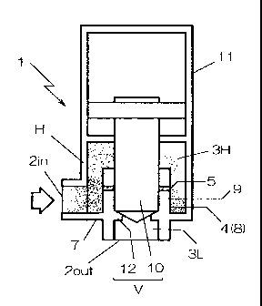
[00121
In a jet dispersing device 1 shown in Fig. 1, the
inside of a housing H is partitioned into a high pressure
region 3H formed with a flow inlet 2in and a low pressure
region 3L formed with a flow outlet 2out by a partition wall
4.
The partition wall 4 is formed with nozzle holes 5,
for jetting a liquid from the high pressure region 3H to
the low pressure region 3L and dispersing the same as fine
6
CA 02546249 2010-07-21
particles, and formed with a cleaning fluid communication
port 6 having a larger opening area compared with that of the
nozzle holes 5, and a valve mechanism V for opening and
closing the cleaning fluid communication port 6 is formed
integrally with the housing H.
[0013]
The partition wall 4 has a tubular member 8 extended
from the bottom 7 to the high pressure region 3H of the
housing H and is formed with fine nozzle holes 5, of
about 0.5 mm in diameter being opposed to each other in a
tubular wall 9 of the tubular member 8, and the end on the
high pressure region is opened as the cleaning fluid
communication port 6.
The cleaning fluid communication port 6 is formed at
an opening area equal with that of the flow inlet 2in and
flow outlet 2out such that no high pressure loss is caused
between the high pressure region 3H and the low pressure
region 3L even when a liquid at high pressure flows in the
jet dispersing device 1 and, accordingly, the liquid can be
caused to flow at a predetermined flow rate necessary for
cleaning even when the cleaning fluid is supplied at a low
pressure.
7
CA 02546249 2010-07-21
[0014]
The valve mechanism V has a rod, as a valve body 10
which is inserted into and withdrawn from the tubular member
8 from the cleaning fluid communication port 6, and the valve
body 10 is adapted to advance and retract by an optional
driving mechanism 11 formed integral with the housing H.
Thus, the cleaning fluid communication port 6 is
opened in a state of where the top end of the valve body 10
is withdrawn from the tubular member 8 and is closed in a
state where it is inserted into the tubular member 8.
Further, so that leakage from the high pressure region
to the low pressure region can be prevented with no provision
of a seal such as an 0 ring in the gap when the valve body 10
is inserted into the tubular member 8 to close the cleaning
fluid communication port 6, the clearance therebetween is
selected as from 0 to 50 m, preferably, 10 to 15 pm.
Further, a valve seat 12 clogged by the top end of the
valve body 10 is formed in the low pressure region 3L of the
tubular member 8 and, when the valve body 10 is inserted as
far as the valve seat 12, since both of the nozzle holes 5,
and the cleaning fluid communication port 6 are closed,
this can be used also as an on-off valve for
8
CA 02546249 2011-10-21
conducting/shutting an optimal flow channel when it is
installed in an in-line arrangement in the flow channel.
[0015]
An example of the constitution of the invention is as
has been described above and the operation thereof is to be
described to a case of applying the jet dispersing device 1
to a coating material supply system 21 of an aqueous two-
component mixed type coating material as an example.
[0016]
A coating material supply system 21 has metering
cylinders 23A, 23B for supplying a main agent and a curing
agent simultaneously each at a flow rate in accordance with
the mixing ratio and a pumping cylinder 24 for storing the
main agent and the curing agent supplied simultaneously and
delivering them at high pressure to a coating machine 22, in
which a jet dispersing device 1 is interposed in a flow
channel 25 from the pumping cylinder 24 to the coalting
machine 22.
Valve devices 27A, 27B for supplying a cleaning fluid
are interposed in the flow channels 26A, 26B extending from
the metering cylinders 23A, 23B to the pumping cylinder 24.
9
CA 02546249 2010-07-21
[0017]
In a case of supplying the main agent and the curing
agent to the coating machine 22, the main agent and the
curing agent are supplied simultaneously each at a flow rate
in accordance with the mixing ratio from the metering
cylinders 23A, 23B, while shutting the flow channel 25 by
advancing the valve body 10 of the jet dispersing device 1 to
close the valve seat 12, the main agent and the curing agent
are mixed at the meeting place for the flow channels 26A and
26B and they are stored in the pumping cylinder 24 with no
leakage to the flow channel 25 as shown in Fig 1(a).
In this stage, while the main agent and the curing
agent are mixed each in an amount corresponding to the mixing
ratio, individual droplets are large in the size with low
uniformness.
[0018]
Then, as shown in Fig. 1(b), when the valve body 10 of
the jet dispersing device 1 is retracted by opening only the
nozzle holes 5, while closing the cleaning fluid
communication port 6, and the coating material is supplied
from the pumping cylinder 24 at a high pressure of about 50
kg/cm` (4.5 MPa), the main agent and the curing agent are
jetted from the high pressure region 3H to the low pressure
CA 02546249 2010-07-21
region 3L upon passage through the nozzle holes 5 and
dispersed in finely particles and, as a result, they are
supplied in a uniformly mixed state to the coating machine 22.
[0019]
Further, upon cleaning, the valve body 10 is retracted
till the top end is completely withdrawn from the tubular
member 8 to open the cleaning fluid communication port 6 as
shown in Fig. 1(c).
Then, when the cleaning fluid is supplied from each of
the valve devices 27A, 27B, the cleaning fluid after cleaning
the inside of the pumping cylinder 24 reaches the jet
dispersing device 1 while cleaning the flow channel 25.
Since the cleaning fluid flowing from the flow inlet
2in into the high pressure region 3H of the jet dispersing
device 1 is discharged by way of a cleaning fluid
communication port 6 having a, larger opening area compared
with that of the nozzle hole 5, it can provide a merit that
the cleaning liquid flows at a constant flow rate necessary
for cleaning the inside of the flow channel 25 even when the
cleaning fluid is supplied at a low pressure, and capable of
cleaning the jet dispersing device 1 and the. flow channel 25
in a short period of time.
11
CA 02546249 2010-07-21
Then, finally, when the valve body 10 is advanced
again while supplying the cleaning fluid as it is, as shown
in Fig. 1(b), to clog the cleaning fluid communication 6 and
also open the nozzle holes 5, even when the nozzle holes 5 of
a small diameter are clogged with the coating material, the
coating material can be finely cleaned and removed.
(0020]
Fig. 3 shows another embodiment of a jet dispersing
device according to the invention. Portions in common with
those in Fig. 1 carry the same reference numerals, for which
detailed descriptions will be omitted.
In the jet dispersing device 31 of this embodiment, an
end of a high pressure region of a tubular member 8 extended
to the high pressure region 3H is opened and formed as a
cleaning fluid communication port 6, and the valve mechanism
V closing the cleaning fluid communication port 6 has'a valve
body 10 inserted to and detached from the inside of the
tubular member 8 from the communication port 6. A
predetermined clearance is formed for the gap between the
valve body 10 to be inserted into the tubular member 8 and
the tubular member 8 such that the gap forms a nozzle hole 5
for jetting the coating material mixture of the main agent
12
CA 02546249 2011-10-21
and the curing agent from the high pressure region to the low
pressure region and dispersing the same as fine particles.
[0021]
With such a constitution, since the cleaning fluid
communication port 6 is opened in a state of withdrawing the
top end of the valve body 10 from the tubular member 8 and,
when the valve body 10 is inserted as far as the valve seat
12 formed on the low pressure region 3L of the tubular member
8, since the nozzle hole 5, and the cleaning fluid
communication port 6 are closed, when the device is disposed
in an optional flow channel in an in-line arrangement, this
can be used also as an on-off valve for conducting/shutting
the flow channel.
[0022]
Further, in the low pressure region 3L of the tubular
member 8, a valve seat 12 to be closed by the top end of the
valve body 10 is formed, by which the cleaning fluid
communication port 6 is opened in a state of withdrawing the
top end of the valve body 10 from the tubular member 8 and
closed in a state of inserting it into the tubular member 8.
Further, when the valve body 10 is inserted as far as
the valve seat 12, since both of the nozzle hole 5, and
13
CA 02546249 2010-07-21
the cleaning fluid communication port 6 are closed, in a case
of providing the same in an optional flow channel in an in-
line arrangement, this can be utilized also as an on/off
valve for conducting/shutting the flow channel.
[0023]
Then, when the jet dispersing device 31 is disposed
instead of the jet dispersing device 1 in the coating
material supply system 21 shown in Fig. 2, the main agent and
the curing agent can be supplied under mixing in the same
manner as described above.
When the main agent and the curing agent are supplied
to the coating machine 22, the valve body 10 of the jet
dispersing device 1 is advanced to close the valve seat 12 as
shown in Fig. 3(a)
Thus, the main agent and the curing agent supplied
from the metering cylinders 23A, 23B are stored in the
pumping cylinder 24 with no leakage to the flow channel 25.
[0024]
Then, as shown in Fig. 3(b), when the valve body 10 of
the jet dispersing device 1 is retracted and stopped at a
position where the top end thereof is slightly inserted into
14
CA 02546249 2010-07-21
the cleaning fluid communication port 6, since a ring-shaped
nozzle hole 5, having a predetermined clearance is formed,
when a coating material is supplied from the pumping cylinder
24 at a high pressure of about 50kg/cm2 (4.5MPa), the main
agent and the curing agent is jetted from the high pressure
region 3H to the low pressure region 3L upon passage through
the nozzle hole 5 and dispersed as fine particles and, as a
result, they are supplied in a uniformly mixed state to the
coating machine 22.
[0025]
Upon cleaning, when the valve body 10 is retracted
till the top end is completely withdrawn from the tubular
member 8 as shown in Fig. 3(c), a cleaning fluid
communication port 6 of a large opening area is opened.
Since the cleaning fluid supplied from each of the
valve devices 27A, 27B reaches the jet dispersing device 1
while cleaning the pumping cylinder 24 and the flow channel
25 and upon entering into the high pressure region 3H from
the flow inlet 2in to the jet dispersing device 1, passes
through the cleaning fluid communication port 6 of a larger
opening area compared with that of the nozzle hole 5 and
discharges to the low pressure region 3L, the cleaning fluid
flows at a predetermined flow speed necessary for cleaning
CA 02546249 2011-07-08
the inside of the flow channel 25 even when the cleaning
fluid is supplied at a low pressure, to provide a merit
capable of cleaning the jet dispersing device 31 and the flow
channel 25 in a short time.
In this case, since the gap forming the nozzle hole is
enlarged to form a cleaning fluid communication port 6, the
coating material clogged in the nozzle hole is also cleaned
and removed simultaneously by supplying the cleaning fluid.
[0026]
In the foregoings while the description has been made
to a case of use for the coating material supply system 21 of
the aqueous two-component mixed type coating material, the
invention is not restricted only thereto but can be used for
liquid supply systems for optional coating materials paints,
and like.
[Industrial Applicability]
[0027]
Since the cleaning fluid communication port of a
larger opening area compared with that of the nozzle hole can
be opened, even when the cleaning fluid is supplied at a low
pressure during cleaning, it can be caused to flow at a
predetermined flow rate necessary for cleaning and it is
16
CA 02546249 2011-10-21
suitable in a case of disposing the same. in the fluid flow
channel in the in-line arrangement, to the application use of
reliably cleaning fluid deposited in the flow channel and the
jet dispersing device in a short period of time.
[Description of References]
[0029]
1, 31 jet sprayer
.H housing
2in flow inlet
17
CA 02546249 2011-07-08
tout flow outlet
3H high pressure region
3L low pressure region
4 partition wall
nozzle hole
6 Cleaning fluid communication port
V valve mechanism
7 bottom
8 tubular member
valve body
12 valve seat
18