Note : Les descriptions sont présentées dans la langue officielle dans laquelle elles ont été soumises.
CA 02546714 2006-05-12 1090P131CA01
,
A method of operating an aircraft system
The invention relates to a method of operating an aircraft system, in
particular for
the purpose of fresh air supply, air conditioning and pressurizing of an
aircraft cabin,
having a first compressed air source formed by a first compressor charged with
ambient air, ram air and/or precompressed air and driven by means of at least
one
motor and/or of at least one turbine and whose outlet is in direct or indirect
communication with the aircraft cabin, said aircraft system having at least
one
second compressed air source whose outlet can be connected directly or
indirectly
to the aircraft cabin.
Aircraft air-conditioning systems having compressors operated with ambient air
are
known in different embodiments. An aircraft air-conditioning system is known
from
WO 2005/030583 Al which has three heat exchangers which are located in a ram
air duct and can be connected to achieve different cooling capacities and thus
different cooling of the compressed air in different manners.
An aircraft air-conditioning system is known from DE 102 34 968 Al in which a
pre-
cooled bleed air flow is combined with a compressed and pre-cooled ambient air
CA 02546714 2013-01-29
- 2 -
flow to form a mixed air flow which is then supplied to suitable means for the
dehumidification of this mixed air flow. The means for the dehumidification of
the
mixed air flow consist of a combined evaporator/condenser unit through which
the two
airflows mixed at the mixing point are guided while increasing the size of the
droplets
contained therein. A further aircraft air-conditioning system is known from DE
103 50
541 Al which is operated without bleed air and whose compressors are charged
with
ram air or ambient air and are driven by means of motors,
There is a problem with compressors charged with ambient air in that the
ambient
conditions, in particular the pressure of the compressor inlet air, vary
considerably in
dependence on the flight altitude. A large demanded operation range results
from this
which cannot be covered completely in an efficient manner by one compressor,
It is therefore the object of the invention to further develop a method of
operating an
aircraft air-conditioning system such that the pressurization, temperature
control and
fresh air supply of an aircraft cabin are ensured in an efficient manner
independently of
the flight altitude.
This object Is solved by a method having the features of the invention.
Provision is
accordingly made for only the first compressed air source to be in
communication with
the aircraft cabin in a first operating mode and for both the first and the
second
compressed air sources to be in communication with the aircraft cabin in a
second
operating mode. The selection of the operating mode depends on the pressure of
the
ambient air such that the first operating mode is set at a high pressure of
the ambient
air and the second operating mode is set at a pressure of the ambient air
lower in
comparison, The method in accordance with the invention thus works in two, or
more
than two, operating modes which mainly depend on the flight altitude and thus
on the
pressure of the ambient air.
In the first operating mode, the air supply is effected only with the named
first
compressor which can, for example, be a single-stage or also a multistage
CA 02546714 2006-05-12
- 3 -
compressor, This compressor guarantees the demands on pressurization,
temperature control and fresh air supply in ground operation.
In a second operating mode, that is at lower ambient pressures such as occur
in
flight, the demanded fresh air mass flow is made available by at least two
sources.
These are the named first compressor, which is charged with ambient air and is
driven by means of a motor and/or of a turbine, and a further compressed air
source. Provision is preferably made for the two mass flows of the compressed
air
sources to be mixed and thus to be supplied to the further treatment, that is
cooling
and dehumidification, for example, before the mixed air flow conditioned in
this way
is supplied to the aircraft cabin, =
It is preferred for the air to be subjected to cooling prior to the entry into
the aircraft
cabin, with the cooling taking place by at least one ram air heat exchanger
located
in a ram air duct of the aircraft and/or by at least one turbine. In the first
operating
mode, the cooling preferably takes place both by the at least one ram air heat
exchanger and by means of one or more expansion turbines integrated in the
cooling process, with them preferably being coupled on a shaft to the first
compressor and to the motor. One or more turbines can thus be located on the
=
shaft with the compressor. The cooling is preferably realized by means of only
one
machine which is integrated in the cooling process in this way and which can
have
one or more turbines.
The arrangement of a plurality of expansion stages, i.e. turbines, with the
compressor on one shaft has the advantage that, for example, one of the
turbines
can be utilized for the cooling and another turbine can be utilized for
another
purpose, for example for the energy recovery by the expansion of cabin air.
The
case is likewise naturally conceivable that all the turbines of the ACM are
used for
cooling purposes. The utilization of the individual expansion stages for
different
purposes can depend, for example, on certain parameters and must therefore not
be identical under all conditions.
CA 02546714 2006-05-12
- 4 -
,
in the second operating mode, provision is preferably made for the outlet air
of the
first compressed air source and at least some of the outlet air of the second
compressed air source to be mixed and for the mixed air flow to be subjected
to
cooling. The cooling can be realized as in the first operating mode by at
least one
ram air heat exchanger and by means of at least one expansion turbine
integrated
in the cooling process.
The mixing point of both flows can e.g. be formed by a chamber, e.g. by a
chamber
for the conversion of ozone or hydrocarbons.
Provision is made in a further aspect of the invention for the outlet air of
the first
and/or second compressors or of the second compressed air source to be
supplied
to a jet pump at least in part. This jet pump can be arranged, for example, in
the
ram air duct of the aircraft and can serve the cooling of a ram air heat
exchanger
and/or the cooling of the motors driving the compressors.
The second compressed air source can be formed by one or more motorized
'
single-stage or multistage second compressors charged with ambient air, ram
air '
and/or precompressed air. It is likewise conceivable for the second compressed
air
source to be formed by engine bleed air.
The invention is not restricted to a first and a second compressed air source.
Any
desired number of further compressed air sources can rather be connected in.
In a preferred aspect of the invention, the first compressed air source and
the at
least one further compressed air source are connected in parallel. The
compressed
air sources can thus, for example, be compressors connected in parallel and
charged with ambient air.
The present invention does not only have the advantage of efficient operation
of an
aircraft system in particular for the purpose of fresh air supply, air
conditioning and
pressurization of an aircraft cabin. A further substantial advantage results
from the
CA 02546714 2006-05-12
- 5 -
redundancy based on the at least two compressed air sources per system. If,
for
example, the motor of one of the compressors is defective, a sufficient supply
of the
aircraft cabin is nevertheless ensured by the other compressed air source both
in
ground operation and in flight operation. Redundancy also results in the case
of two
aircraft systems or of two aircraft air-conditioning systems which communicate
with
one another between themselves by means of a line (cross bleed ducting), as
will
be explained in more detail below.
The above recitations with respect to the first and second or further
operating
modes apply to the normal case. In the effect of a defect, such as on the
failure of
the first compressor, other connections can be made which differ from this.
If, for
example, the first compressor fails, provision can be made for the supply of
the
aircraft cabin to be carried out by means of the second compressed air source,
even if the first operating mode would actually have to be selected at the
prevailing
ambient conditions. =
In a further aspect of the invention, provision is made for a water extraction
circuit to
be provided downstream of the compressed air sources and upstream of the cabin
as well as for a turbine to be provided downstream of the water extraction
circuit
and for a third operating mode to be provided in which both the first and the
second
compressed air sources are in communication with the aircraft cabin and in
which
the compressed air is guided around the water extraction circuit and the
turbine in a
partial or complete bypass. The provision of fresh air first takes place in
this mode
as in the first or second operating modes. However, due to the ambient
conditions
at a high flight altitude, the water extraction circuit and the turbine stage
can be
bypassed at least partially by opening a bypass valve. Cooling now takes place
in
this case substantially via the ram air heat exchanger or exchangers.
Provision is made in a further aspect of the invention for the air to be
subjected to
cooling prior to entry into the aircraft cabin, with the cooling taking place
by at least
one ram air heat exchanger located in a ram air duct of the aircraft and by
one or
more expansion turbines which are charged completely or partially and which
are
CA 02546714 2006-05-12
- 6 -
seated with the first compressor on a shaft. Provision is preferably made for
the
cooling to be realized in addition to the ram air heat exchanger or exchangers
by
means of only one ACM which is integrated in the cooling air process and which
can in turn have one or more turbines. This turbine or these turbines is/are
preferably coupled to the compressor and the motor on a shaft.
Since the second or the further compressed air sources are preferably only
switched in from a certain altitude in flight in accordance with the
invention, they can
be used at least partially for the demand of the cooling air for the ram air
heat
exchangers on the ground, that is in the first operating mode.
It is conceivable in this process for the compressor extracted air to be
supplied via
regulation valves or check valves partially or exclusively to a jet pump
integrated in
the fan chamber of the ram air duct, This jet pump ensures the cooling air
flow via
the ram air heat exchangers. The jet pump can be made with sound-absorbing
measures such as a specific shape of the flow cross-section and/or specific
sound-
= absorbing layers. It is generally also conceivable also to connect the
second
compressed air source to a jet pump in a different operating mode to the first
operating mode. Generally, the first compressor can also be in communication
with
a jet pump irrespective of the operating mode.
It is likewise conceivable for an impeller, which is integrated in the ram air
duct or
the fan chamber (plenum), to be utilized for the suction of ambient air via
the ram air
heat exchanger or exchangers. The impeller is coupled with the motor
compressor
on a shaft. The air transported by the compressor which is also running in
this
solution cart either be blown out to ambient or be utilized in the ram air
duct for the
support of the fan via a jet pump or be supplied to further consumers.
It is also conceivable to arrange one or more fans independently of the
compressor
or compressors. One or more fans can thus be provided which are used for the =
cooling of the compressor motor or motors and/or of the ram air heat exchanger
or
CA 02546714 2006-05-12
- 7 -
=
exchangers and which are not coupled to the compressors or are not seated with
them on a shaft,
The fan chamber can have branches in the flow guidance. Provision can be made
in this process for the ram air duct to have one or more partition walls
extending in
the flow direction at least sectionally which divide the ram air duct into at
least two
= sections, with a jet pump communicating with the second compressed air
source or ,
an impeller coupled to the second compressor being arranged in the first
section
and with the second section representing a bypass of the first section for the
air
= flowing through the ram air duct. The cooling air of the ram air heat
exchangers is
preferably transported under ground conditions in the first section. The jet
pump
and the impeller are arranged in this section, with them being able to be
arranged ,
jointly in one branch or separately in adjacent branches. The cooling air of
the ram
air heat exchangers is preferably transported under flight conditions in the
second
section. A bypass of the jet pump or of the impeller thus results whereby the
transmission is increased, This bypass - or another branch - supports the
secure
ventilator operation in which a recirculation flow is enabled, provided the
fan is
coupled to a compressor,
A further section can be provided in the ram air duct in which a jet pump
and/or a =
fan is/are arranged for the purpose of cooling the motors driving the
compressors.
Provision is thus made in a further aspect of the invention for a jet pump or
a fan to
be provided for the purpose of cooling one or more motors driving the
compressor
or compressors.
The time of the switching in of the parallel compressors or compressed air
sources
can depend on different criteria.
It is possible to switch over from the first to the second operating mode when
the
packing limit of the first compressor is reached or when the maximum motor
power =
of the first compressor is reached. Providing the same motor size with all
=
CA 02546714 2006-05-12
- 8 -
compressors is conceivable, which requires an earlier switching in of the
additional
=
compressors.
When the second compressor or the second or a further compressed air source
per
pack is switched in, a halving/reduction of the mass flow for the first
compressor
takes place since the second compressor or the further compressed air source
now
transports the mass flow now lacking to cover the required fresh air amount.
This
can have the result that the new operating point can lie in the instable range
to the
left of the pump limit (surge line) at least for the first compressor.
Different
measures can be taken to enable a secure, that is stable, operation.
It is possible to increase the fresh air amount for the cabin in the second
operating
mode and also in the third operating mode. An increase in the fresh air amount
is
generally also conceivable in other operating modes, e.g. in the first
operating ,
mode.
It is likewise conceivable to increase the mass flow via the compressor stages
through recirculation, with a valve (anti-surge valve (ASV) being able to be
arranged
in the recirculation line. This increase in throughflow does not serve the
increase in
the fresh air amount, but only the component security. Such a recirculation is
conceivable irrespective of the operating mode, i.e. it can be selected in the
first,
second, third operating modes, etc.
It is furthermore conceivable that, in the first or second operating mode, the
outlet
air of the first compressor and/or of the compressors is supplied to the
second
compressed air source and/or to a further compressed air source via a jet pump
via
the ram air duct of the aircraft or to further consumers of the aircraft. This
method of
operation is conceivable in the first or second operating modes, but also in
other
operating modes.
This also results in operation of the compressors in the stable range for any
desired
mode.
CA 02546714 2006-05-12
,
,
- 9 -
,
,
,
These further consumers can, for example be the systems BOGS, OBIGGS, WAI
,
(wing anti-ice) or a further heating/cooling. It is furthermore conceivable to
utilize the
outlet air for the engine start or for the start of an auxiliary engine (APU),
,
To limit the required motor power, the transmission of the pack can be
increased in
,
dependence on the demanded cooling capacity and on the air dehumidification
via
the water extraction circuit. Different possibilities are available for this
purpose:
It is conceivable to adapt the required motor power ideally via a variable
turbine
guidance apparatus via an adaptation of the cross-sectional area. The
important
,
design point for the turbine nozzle is the ground case with maximum cooling
capacity and high air humidity. As the flight altitude increases, an increase
in the
size of the nozzle area is necessary, The control of this turbine guide
apparatus can
take place, for example, electrically, electropneumatically or also purely
pneumatically.
,
The transmission can furthermore be increased in that a bypass line is opened
at a
large flight altitude at low ambient humidity which bypasses the water
extraction :
,
,
circuit and the turbine. This is possible because no more dehumidification is
necessary at high flight altitudes. The valve BPV is arranged in this bypass
line,
With a fully open BPV, the required cooling capacity must be achieved by the
ram
,
air heat exchanger since the turbine stage is almost completely bypassed due
to
the higher transmission of the bypass line, If a higher cooling capacity is
necessary,
the BPV may only move into regulation to achieve additional turbine cooling
capacity or other cooling capacity, whereby a higher pressure ratio of the
,
compressors and thus more motor power is required.
,
Provision can further be made for a common control unit to be provided for the
valve TCV, which is disposed in a line which connects the outlet of the
compressed .
air source or the mixed air line to the outlet of the turbine, and for this
guide
apparatus, whereby only one single actuator is required for this control.
,
,
,
,,
CA 02546714 2006-05-12
- 10 -
On the ground and at a low flight altitude, it can be necessary to take
suitable
measures to increase the heating capacity of the air-conditioning system.
Different ,
possibilities are likewise available for this purpose.
It is conceivable to allow some of the compressed air to recirculate via the
compressors for the purpose of increasing temperature, whereby the temperature
of
the process air is increased and thus the heating capability of the air-
conditioning
system is also increased,
It is likewise conceivable to increase the outlet temperature by a valve for
the ,
throttling of the compressors and, on the other hand, to enable a bypass of
the
turbine stage.
It is furthermore possible to design the guide apparatus of the turbine via
variable
changes in the cross-sectional surface such that the heating capability of the
air-
conditioning system is also thereby ensured under ground conditions,
It is furthermore possible to influence the heating capacity in that the ram
air
amount is reduced. This can take place in that the ram air duct is closed
partially or
fully by means of a flap or valve controlled via an actuator. It is likewise
conceivable
to reduce or cut off the compressed air supplying the jet pump located in the
ram air
duct or to change the pressure level and the throughput.
A further possibility consists of adapting the power of the impeller located
in the ram
air duct.
The motor cooling can be realized by the use of ambient air or ram air or by
means
of a liquid coolant circuit or two-phase coolant circuit. A separate jet pump
must
optionally be provided for the motor cooling duct. The cooling can take place
by
means of ambient air or ram air.
CA 02546714 2006-05-12
,
,µ
- 11 -
The water extraction circuit of the air-conditioning system typically includes
a "
reheater, a condenser downstream of it on the compressed air side and a water
extractor downstream of it. This water extraction circuit can generally also
be '
designed without a reheater.
Provision is made in a further aspect of the invention for a first air-
conditioning
system and a second air-conditioning system to be arranged which are operated
,
according to a method in accordance with one of the claims Ito 29, with the
second
compressed air source being formed by two motorized compressors charged with =
ambient air, ram air or precompressed air or by two other compressed air
sources
such as engine bleed sources, with one of the second compressed air sources
being switched in to both air-conditioning systems in the second operating
mode
and with the second compressed air sources being switched in to one each of
the
two air-conditioning systems in a further operating mode. Such a method has
the
advantage that the reduction in the mass flows for the first compressors of
the air-
conditioning system does not turn out to be so strong on the change from the
first to
the second operating mode since the mass flow of the switched in compressor or
of
the switched in compressed air source is first divided between both air-
conditioning
systems.
This effect can naturally also be realized in that the second compressed air
source
is only formed by a motorized compressor charged with ambient air, ram air or
precompressed air or only by a bleed air source. This one second compressed
air
source can be switched in to both air-conditioning systems or both aircraft
systems
at reduced capacity In the second operating mode so that the reduction of the
mass
flow of the first compressor only turns out relatively low. In a further
operating mode,
the second compressed air source can be switched in to both air-conditioning
systems with a mass flow higher in comparison.
The connection of second air-conditioning systems or aircraft systems by a
connection line results in a likewise redundant design so that a fault case in
one of
the air-conditioning packs or systems can be compensated largely or
completely.
CA 02546714 2006-05-12
15
- 12
=
Further details and advantages of the invention will be explained in more
detail with
reference to an embodiment shown in the drawing. There are shown;
=
Figure 1: a schematic representation of an aircraft air-conditioning system to
which ' =
the method in accordance with the invention is applied;
Figure 2: a schematic representation of the aircraft air-conditioning system
of
Figure 1 in a particular embodiment; and
Figure 3: a schematic representation of the aircraft air-conditioning system
for the
carrying out of the method in accordance with the invention.
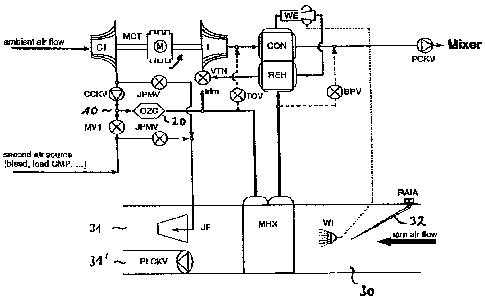
Figure 1 shows, with reference numeral Cl, a first compressor charged with
,
ambient air. It is in communication with a motor M and an expansion turbine T
on a
shaft. The total unit is called an MCT (motorized compressor turbine). The
swung
arrow in the region of the motor M is intended to indicate its cooling, for
example by
means of a jet pump or a fan, which can be arranged e.g. in the ram air duct.
The
same applies correspondingly to Figures 2 and 3.
A further compressed air source, "second air source", is provided in addition
to the
compressed air source and is switched in depending on the operating mode in
which the system is operated. This compressed air source can be switched in or
off
or also partially switched in by means of the valve MV1 (modulating valve 1).
A
check valve can also be arranged instead of the valve MV1. This second
compressed air source can, for example, be a second motorized compressor
charged with ambient air or also bleed air from the engine of the aircraft.
The outlet
line of the compressor Cl has a check valve CCKV which ensures that the flow
through this outlet line does not lead toward the compressor.
The outlet lines of the compressor Cl and of the further compressed air source
are
connected to one another at a mix point 10. A chamber 20 is located downstream
of
=
CA 02546714 2006-05-12
- 13 -
=
the mix point in which, for example, a converter for ozone and/or for
hydrocarbons ,
(OZC) can be arranged.
The ram air heat exchanger MHX is located downstream of this chamber and is
arranged in the ram air duct 30 of the aircraft, as can be seen from Figure 1.
The
ram air duct heat exchanger MHX is in communication with a water extraction
circuit
consisting of a reheater REH, a condenser CON and a water extractor WE on the
outlet side, with the components being arranged in the order reheater,
condenser
and water extractor, The water extractor WE is in communication with the cold
side
of the reheater REH on the outlet side. On the outlet side, the cold side of
the
reheater is in communication with the turbine T, which is connected upstream
of the
turbine T, via a guide apparatus VTN (variable turbine nozzle). The cold
turbine
outlet air flows through the condenser CON on its cold side and is then
supplied to
a mixing chamber or to the aircraft cabin after passing through a check valve
PCKV
(pack check valve).
=
The water separated in the water extractor WE is supplied to the ram air duct
30 via
a water injector WI, as can be seen from Figure 1. A ram air duct inlet valve
32 is
=
located at the inlet side of the ram air duct and can be moved into different
positions
by means of the RAIA (ram air inlet actuator),
The ram air duct is divided into two sections 31 and 31' on the ram air side
downstream of the ram air duct heat exchanger MHX. The jet pump JP is located
in
the section shown above and is in communication with the outlet lines of the
compressors or compressed air sources via valves JPMV (jet pump modulating
valve).
A line extends from the mixed air line downstream of the chamber 20 and
upstream
of the ram air duct heat exchanger MHX to the outlet side of the turbine T in
which a
,
=
valve TCV (temperature control valve) is arranged. Furthermore, a bypass line
is
provided which leads from the outlet side of the ram air duct heat exchanger
MHX
CA 02546714 2006-05-12
- 14 -
,
to the line of the air-conditioning system leading to the mixing chamber. The
valve
BPV (bypass valve) is located in this line.
The system of Figure 1 is operated as follows. In a first operating mode, the
total
fresh air is only made available by the compressor Cl, The latter is
preferably made =
with a single-stage, with a multistage design generally also being possible.
This =
compressor serves to guarantee the demands with respect to pressurization,
"
temperature regulation and fresh air supply. The compressor outlet air is
first cooled
in the ram air duct heat exchanger MHX after passing through the chamber 20,
This
air subsequently flows through the water extraction circuit and is then
subjected to a
second cooling in the single turbine T in the cooling process. The turbine
power
serves, together with the power of the motor M, the drive of the compressor
Cl. The
cold turbine outlet air serves the condensation of the humidity of the outlet
air of the
=
ram air duct heat exchanger in the condenser CON.
In a second operating mode, the valve MV1, or a check valve, is opened and the
fresh air mass flow is now formed by the outlet air of the compressor Cl and
by the
compressed air flow of the second compressed air source. In the second
operating
mode, the mixed air flow flows through the same components as the outlet air
of the
compressor C1 in the first operating mode.
In a third operating mode, the provision of the fresh air first takes place as
in the
second operating mode, However, due to the ambient conditions at a high flight
altitude, the water extraction circuit and the turbine stage can be bypassed
at least
partially by opening the valve BPV. The cooling in the third operating mode
now
takes place substantially by means of the ram airduct heat exchanger MHX,
Due to the high demanded pressure ratio of the individual compressor stages
based
on single-stage compression, these compressor stages only achieve a limited
operating range for the corrected mass flow. To be able to deliver the mass
flow
(volume flow) corrected as the flight altitude increases, influenced by
falling
compressor inlet pressure, additional compressor stages or compressed air
sources
CA 02546714 2006-05-12
- 16 -
are switched in parallel in dependence on the flight altitude. The number of
ambient
=
air compressors utilized is not fixed in this connection, with a parallel
connection of
at least two compressed air sources per pack (air-conditioning system) taking
place
to cover the total application area.
As can furthermore be seen from Figure 1, the second compressed air source can
be used with an open valve JPMV to operate the jet pump JP. This has the
result '
that a coolant air flow is also ensured in the first operating mode via the
ram air heat
exchanger or exchangers. As can further be seen from Figure 1, the compressor
outlet air of the compressor Cl can also be supplied to the jet pump via a
valve
JPMV. Such a procedure is in particular sensible to ensure a safe/stable
operation
of the compressor Cl. The additional mass flow is thereby directed via the jet
pump
JP into the ram air duct or is alternatively supplied to further consumers.
To increase the transmission of the air-conditioning system, the cross-
sectional
surface can be adapted ideally via a variable turbine guide apparatus. The
unit TVN
of the turbine T serves this purpose. The unit can be controlled with the
valve TCV =
serving for the temperature control by means of a common actuator.
= Figure 2 shows an aspect of the arrangement of Figure 1, with the second
= compressed air source being formed by a compressor C2 which is driven by
a
motor M. A turbine is not provided so that an arrangement MC (motorized
compressor) is obtained. One or more of these units can also be provided. The
operating method of the air-conditioning system shown in Figure 2 corresponds
that
explained with reference to Figure 1 so that reference is made accordingly. In
addition to Figure 1, recirculation lines which can be closed by a valve ASV
(anti-
surge valve) are drawn for the compressors Cl and C2. Furthermore, a further
valve CLV (compressor load valve) is provided in the line extending from the
chamber 20 to the ram air duct heat exchanger MHX. The recirculation air can
be
increased via the compressor by opening the valve ASV, whereby a safe, stable
operation of the compressors Cl, C2 is enabled. As stated above, the increase
in
the compressor mass flow can also be realized via the jet pump modulating
valves
CA 02546714 2006-05-12
. .. .
. .
- 16 -
. .
I
= I
I
=
I
I
JPMV. The valve CLV shown in Figure 2 serves the restriction of the
compressors
,
..
, Cl, 02 by which the exit temperature of the compressors Cl, C2 is
increased.
õ
Figure 3 shows a further variant of an air-conditioning system operated
according to ,
the method in accordance with the invention. The operation of the air-
conditioning
system explained with reference to Figure 1 and Figure 2 results for ground
operation and low flight altitudes, The arrangement of Figure 3 enables the
step-
, ,
.
wise switching in of the motorized compressors C3 and C4 charged with ambient
,
air, whereby the problem is reduced that the compressors Cl and C2 of the
right = '
hand or left hand pack are operated in the unstable range.
,
,
Provision is made in accordance with Figure 3 that only one of the additional
,
= compressors C3 or C4 is operated in parallel with the compressors of
the LH and .
RH packs from a certain flight altitude. This has the consequence that the
reduction
,
in the mass flows for the first compressors Cl and C2 does not turn out so
strong
and an operating point in the stable range (to the right of the pump limit
(surge line))
remains possible. To split the mass flow of the switched in compressor (C3 or
C4) '
,
to both packs, they are connected to one another via a line 40 (cross bleed
ducting). The valve CBSOV (cross bleed shut-off valve) is arranged in this
line and
,
, the line 40 can be opened or closed by means of it.
The connection of both air-conditioning systems by the cross bleed ducting
results
in a redundant embodiment since each of the air-conditioning systems can be
connected to compressed air sources associated with the other air-conditioning
system as required.
,
At a greater flight altitude, the further additional compressor (C3 or C4) can
also be '
switched in parallel. The valve CBSOV is closed so that two separate packs are
.
again operated comparably with the second operating mode with respect to
Figure =
1 and Figure 2,
,
, ,